
Related Manuals for RTS BTR-800


Summary of Contents for RTS BTR-800
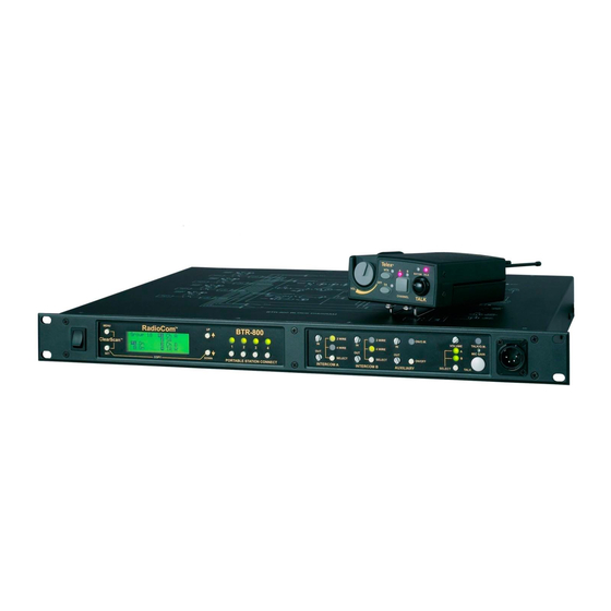
- Page 1 BTR-800, TR-800, TR-825 Professional Wireless Intercom System Operating Instructions Rev. 19 JUNE / 2019 F.01U.187.426...
- Page 2 BTR-800, TR-800, TR-825...
-
Page 3: Table Of Contents
General Description ..........7 Auxiliary ..............38 System Features ............ 7 Display Contrast ............39 BTR-800 Menu Structure ........40 BTR-800 BASE STATION .......9 Main Screen Flowchart ..........40 Controls and Connections – Front Panel ....9 Power-Up Screen .............41 BTR-800 Specifications .......... 11 Operating Screen .............41... - Page 4 BTR-800, TR-800, TR-825 Wireless Talk Around ..........68 Audio Channel A Options ........69 Audio Channel B Options ........70 Special Key Sequences ........... 71 Lockout ..............71 1st Use Default ............71 Factory Default ............71 SYSTEM WALK-THRU ......... 73 ...
-
Page 5: Introduction
Audiocom (Telex), RTS station. TW, Clear-Com, as well as RTS Matrix systems and other 4- SA (Stage Announce) beltpack control. Allows the user to •... - Page 6 8 Introduction BTR-800, TR-800, TR-825 BTR-800 Block Diagram FIGURE 1.
-
Page 7: Btr-800 Base Station
CHAPTER 2 BTR-800 Base Station Controls and Connections – Front Panel Power Switch release latches button on. If the talk function is latched on, pressing the talk button again turns it off. [MENU] and [SET] buttons - Use to select menus and set options on the LCD. - Page 8 I/C Select Switch – Set to the appropriate 2-wire intercom mA current in the 2-wire loop thru circuits. type being interfaced to the unit. Set to either Telex, RTS, or Clear-Com. Base Station Link Jack – When two base stations are 4-Wire –...
-
Page 9: Btr-800 Specifications
BTR-800, TR-800, TR-825 BTR-800 Base Station 11 BTR-800 Specifications Internally Adjustable (2 Vrms typical at rated deviation into 600Ω) Overall Stage Announce Relay RF Frequency Range Dry contact, rated at 1 Amp, 24V Max TX Range Microphone input sensitivity 482-608 MHz in 18 MHz TX bands... - Page 10 12 BTR-800 Base Station BTR-800, TR-800, TR-825...
-
Page 11: Tr-800 Beltpack
CHAPTER 3 TR-800 Beltpack Controls and Connections – Top Panel FIGURE 4. TR-800 Top Panel On/Off & Volume Control – Turns the beltpack power is dead. A normal microphone gain setting will cause the on and controls headset volume. LED to flash at the beginning of most words at normal speech levels. - Page 12 14 TR-800 Beltpack BTR-800, TR-800, TR-825 Male Connector Female Connector FIGURE 5. TR-800 Rear Panel/Connector/Antennas [MENU] and [SET] buttons – Used to select menus and set option on the LCD LCD (Liquid Crystal Display) [UP] and [DOWN] buttons – Used to select beltpack options on the LCD.
-
Page 13: Tr-800 Specifications
BTR-800, TR-800, TR-825 TR-800 Beltpack 15 TR-800 Specifications RF Frequency Stability 0.005% RF Frequency Range Modulation Limiter US/Canada TX Range Peak-Responding Compressor 572-608 MHz in 18 MHz TX bands 653-663 MHz for 3 bands Radiated Harmonics & Spurious 470-488 MHz for 88 band... - Page 14 16 TR-800 Beltpack BTR-800, TR-800, TR-825...
-
Page 15: Tr-825 Beltpack
CHAPTER 4 TR-825 Beltpack Controls and Connections – Top Panel FIGURE 7. TR-825 Top Panel On/Off and Volume Control – Turns beltpack power on audio. The button is non-latching and activates the nearby and controls headset volume for Intercom Channels A and red LED. - Page 16 18 TR-825 Beltpack BTR-800, TR-800, TR-825 Male Connector Female Connector FIGURE 8. TR-825 Rear Panel/Connector/Antennas [MENU] and [SET] buttons – Used to select menus and set options on the LCD. LCD (Liquid Crystal Display) [UP] and [DOWN] buttons – Used to select beltpack options on the LCD.
-
Page 17: Tr-825 Specifications
BTR-800, TR-800, TR-825 TR-825 Beltpack 19 TR-825 Specifications RF Frequency Stability 0.005% RF Frequency Range Modulation Limiter US/Canada TX Range Peak-Responding Compressor 572-608 MHz in 18 MHz TX bands 653-663 MHz for 3 band Radiated Harmonics & Spurious 470-488 MHz for 88 band... - Page 18 20 TR-825 Beltpack BTR-800, TR-800, TR-825...
-
Page 19: Initial Equipment Setup
Contact the shipper or your dealer immediately if anything is damaged or missing. Fill out the registration card and return it to Unpacking your RTS System. Below are the items that should Bosch to register the unit. come with your base station and each beltpack. -
Page 20: Antenna Connection
The antennas can be remoted for better signal path. An RTS coax assembly with remote antennas may be required. See “Accessories and Replacement Parts” on page 83 for ordering information. - Page 21 BTR-800, TR-800, TR-825 Initial Equipment Setup 23 Keep the distance between the base station and the beltpacks as short as possible. The greater the distance, the weaker the signal. Make sure the signal paths between the base station and beltpacks are unobstructed. You should be able to visibly locate the base station antennas at all times for best performance.
-
Page 22: Improving Reception And Increasing Range
24 Initial Equipment Setup BTR-800, TR-800, TR-825 Antenna Placement FIGURE 17. Improving Reception and Increasing Range The base station is supplied with two antennas. This should provide satisfactory system performance in most applications. Keeping the distance from the base station and beltpack as short,... -
Page 23: Base Station Set-Up
BTR-800, TR-800, TR-825 Initial Equipment Setup 25 Base Station Set-up FIGURE 18. Base Station – Rear Panel Location Transmit Switches Locate the base station with the front and rear of the unit There are two switches located on the lower left side of the rear accessible so that switches may be set and connections made. -
Page 24: Internal Transmit Switches
XLR connectors when in RTS mode. RTS channel 1 is place on intercom A and RTS channel 2 is placed on intercom B as long as the RTS TW input to the base station is wired as in “Intercom Systems Specifications” on page 81. - Page 25 BTR-800, TR-800, TR-825 Initial Equipment Setup 27 FIGURE 21. Example Interface to an RTS TW System...
-
Page 26: Dual Listen Functionality
28 Initial Equipment Setup BTR-800, TR-800, TR-825 Dual Listen Functionality of the mix can be controlled at the TR-825 via the two volume controls. The base station’s main audio board has the option of placing additional parts to enable dual listen. Dual listen allows the They will also have the ability to control the level of the mix (- mixing of the intercom channels. -
Page 27: Auxiliary Input/Output
BTR-800, TR-800, TR-825 Initial Equipment Setup 29 Auxiliary Input/Output and any wired intercom connected to the base station. A modification document is available from Bosch Security The input and output 3-pin XLR auxiliary connections are for System, Inc. for those who wish to modify the base station so supplying additional balanced audio into and receiving balanced that auxiliary input audio is heard only locally;... -
Page 28: Stage Announce / Relay Contacts
30 Initial Equipment Setup BTR-800, TR-800, TR-825 FIGURE 24. Base Station – Rear Panel Stage Announce / Relay Contacts A relay contact closure is also activated when a beltpack user presses the [SA] button. The contacts are normal open (N.O.). -
Page 29: Base Station Link
BTR-800, TR-800, TR-825 Initial Equipment Setup 31 FIGURE 28. Base Station – Rear Panel Base Station Link A cable to accomplish this task is NOT supplied, but can easily be made with common category 5 (CAT-5) or later wiring. This RJ-45 type jack allows the connection of wireless talk around (WTA) to two base station of the same frequency bands. -
Page 30: Beltpack Setup
32 Initial Equipment Setup BTR-800, TR-800, TR-825 Beltpack Setup Tuck end of strap under door when placing the battery cover back on the case. Battery Installation Ensure that the On/Off volume control knob is turned off. Press down and hold down the battery release latch, slide the battery pack about 1/8-inch back, toward the latch, until it stops. -
Page 31: Antenna Connection
BTR-800, TR-800, TR-825 Initial Equipment Setup 33 FIGURE 32. TR-800 and TR-825 Rear Panel FIGURE 33. Antenna Connection Headset Connection The beltpack comes with two detachable, screw-type, 1/4-wave Insert the headset plug into the XLR connector. See the headset antennas. To attach the two antennas, screw into the receptacles pinout in the TR-800/TR-825 beltpack controls and connections at the bottom of the beltpack. - Page 32 34 Initial Equipment Setup BTR-800, TR-800, TR-825...
-
Page 33: Pre-Walk-Thru Checklist
CHAPTER 6 Pre-Walk-Thru Checklist Following the instructions fully to this point you have ❐ successfully completed the following checklist: Connected the base station to any auxiliary audio, intercom, external P.A. system, or relay contact detect circuit, if needed. ❐ Located the base station properly. ❐... - Page 34 36 Pre-Walk-Thru Checklist BTR-800, TR-800, TR-825...
-
Page 35: System Operation
Matrix and stand-alone operation. For example, one BTR-800 could be set on Group 02A and channels 01, 02, 03, and 04. The other BTR-800 could set on Pace batteries in the beltpacks. Group 02B channels 05, 06, 07, and 08. As long as the channels Remove the rear switch cover on the beltpacks. -
Page 36: Base Station Operation
Audiocom (Telex), RTS TW or Clear-Com, set the intercom to Equipment Setup, you should now be ready to turn the base 2-wire. If it is connected to a 4-wire system, such as RTS station on. Matrix, set the intercom to 4-wire. It is also possible to have... -
Page 37: Display Contrast
Display Contrast adjust the contrast, if desired. The contrast control is internal to the BTR-800 unit near the front panel. The cover must be The LCD’s (Liquid Crystal Display) contrast is set from the removed for access to this control. See Figure 35. -
Page 38: Btr-800 Menu Structure
40 System Operation BTR-800, TR-800, TR-825 The following contains the base station menu structure and BTR-800 Menu Structure references the pages in which further detail of that menu may be found. Main Screen Flowchart FIGURE 36. Power-Up Screen NOTE: Pressing [MENU] within a screen after action has... -
Page 39: Power-Up Screen
BTR-800, TR-800, TR-825 System Operation 41 Power-Up Screen This screen is displayed only on power up, first use default and factory default. • The 1st upper right corner number displays the base’s software revision. The single version number increments for changes in •... -
Page 40: Beltpack Activity Code Definitions
Beltpack Channel B Talk Around Active TA A&B Beltpack Channel A and B Talk Around Active (TR-825 only) Beltpack Stage Announce Active NOTE: Older versions of BTR-800 software do not support the detection of TR-825 Ch A&B and TA A&B control tones. -
Page 41: Group/Channel Select
BTR-800, TR-800, TR-825 System Operation 43 Group/Channel Select The Group/Channel select screen allows the user to change the group and select from a pre-determined number of channels on each receiver. Press [MENU] once to enter the Group/Channel Select • Screen from the operating screen. -
Page 42: Group/Frequency Select
44 System Operation BTR-800, TR-800, TR-825 Group/Frequency Select The Group/Frequency select screen allows a user to set the group and select from a pre-determined number of frequencies on each receiver. Each frequency displayed on the right half of the screen corresponds to a channel number in the Group/ Channel Screen. -
Page 43: Frequency Edit (User-Programmed Groups Only)
BTR-800, TR-800, TR-825 System Operation 45 Frequency Edit (User-Programmed Groups Only) This menu only occurs for user-programmable groups or when copying to a user-programmable group. The Frequency Edit screen allows the user to set the group transmit frequencies and receive channel frequencies of a user-programmable group. -
Page 44: Clearscan
BTR-800, TR-800, TR-825 ClearScan™ To achieve the best results quickly when using ClearScan™, please complete the following for setting up a sing BTR-800 ClearScan™ performs a frequency scan of the factory-defined system: and any set-up user-programmable groups in order to find the group with the highest number of clear receive channels. -
Page 45: Special Key Sequences
BTR-800, TR-800, TR-825 System Operation 47 Special Key Sequences 1st Use Default Lockout Press [MENU] while turning on the base station to enter the • 1st use default setup screen. This places the unit on group Press [UP]+[DOWN] for three seconds to lock or unlock •... -
Page 46: Beltpack Operation
48 System Operation BTR-800, TR-800, TR-825 Beltpack Operation FIGURE 37. TR-800 and TR-825 Top and Rear Panel On/Off and Volume Control maximized, and headset volume reduced to make up for the louder audio, the audio will still sound good and not clipped. -
Page 47: Tr-800 Menu Structure
BTR-800, TR-800, TR-825 System Operation 49 The following contains the main beltpack menu structure and TR-800 Menu Structure references the pages in which further detail of that menu may be found. Beltpack Menu Structure All beltpack features and special key sequences can only be done from the group/channel screen. -
Page 48: Power-Up Screens
50 System Operation BTR-800, TR-800, TR-825 Power-Up Screens The first screens displayed when the beltpack is powered up • are the software and channel map version screens. The 1st screen displayed indicates the beltpack’s software • version number. It is displayed for about one second. -
Page 49: Group/Channel Screen
BTR-800, TR-800, TR-825 System Operation 51 Group/Channel Screen The Group/Channel screen allows the user to change the group and select from a pre-determined number of transmit channels. The screen displayed after the beltpack power-up screens. • Press [SET] to edit the channel number. The channel •... -
Page 50: Transmit Screen
52 System Operation BTR-800, TR-800, TR-825 Transmit Screen The Transmit screen allows the user to set the beltpack transmit frequency. Factory-defined groups will allow only a set number of pre-defined frequencies to be selected. User-programmable groups will allow the user to change the frequency in 25kHz steps. -
Page 51: Receive 1 Screen
BTR-800, TR-800, TR-825 System Operation 53 Receive 1 Screen The Receive 1 screen allows the user to set the beltpack receive 1 frequency. This corresponds to the base station’s transmit 1 frequency. In factory-defined groups, receive 1 is not changeable. User-programmable groups will allow the user to change the frequency in 25 kHz steps. -
Page 52: Receive 2 Screen
54 System Operation BTR-800, TR-800, TR-825 Receive 2 Screen The Receive 2 screen allows the user to set the beltpack receive 2 frequency. This corresponds to the base station’s transmit 2 frequency. In factory-defined groups receive 2 is not changeable. User-programmable groups will allow the user to change the frequency in 25 kHz steps. -
Page 53: Clearscan
BTR-800, TR-800, TR-825 System Operation 55 ClearScan™ ClearScan™ performs a frequency scan of the factory-defined and any setup user-programmable groups in order to find the clearest group. After about 30 seconds, the clearest group is displayed. A group is defined by receive 1 and 2 frequencies. -
Page 54: Stage Announce Enable/Disable
56 System Operation BTR-800, TR-800, TR-825 Stage Announce Enable/Disable Press and hold [SET] then press the [SA] button to show the • SA enable/disable screen. The current setting of the feature is displayed on the LCD. While continuing to hold [SET] press [SA] again to toggle •... -
Page 55: Audio Channel A Or B Disable/Enable
BTR-800, TR-800, TR-825 System Operation 57 Audio Channel A or B Disable/Enable Press and hold [SET] the press the [CHAN] button to show • the channel enable/disable screen. The current setting of the feature is displayed on the LCD. While continuing to hold [SET], press the [CHAN] button •... -
Page 56: Special Key Sequences
58 System Operation BTR-800, TR-800, TR-825 Special Key Sequences Lockout Press [UP]+[DOWN] for three seconds to lock or unlock • the beltpack. The words “Loc on” will be displayed when the feature is activated, “Loc oFF” will be displayed when the beltpack is unlocked. -
Page 57: Tr-825 Menu Structure
BTR-800, TR-800, TR-825 System Operation 59 The following contains the main beltpack menu structure and TR-825 Menu Structure references the pages in which further detail of that menu may be found. Beltpack Menu Structure All beltpack features and special key sequences can only be done from the group/channel screen. -
Page 58: Power-Up Screens
60 System Operation BTR-800, TR-800, TR-825 Power-Up Screens The first screens displayed when the beltpack is powered up • are the software and channel map version screens. The 1st screen displayed indicates the beltpack’s software • version number. It is displayed for about one second. -
Page 59: Group/Channel Screen
BTR-800, TR-800, TR-825 System Operation 61 Group/Channel Screen The Group/Channel screen allows the user to change the group and select from a pre-determined number of transmit channels. The screen displayed after the beltpack power-up screens. • Press [SET] to edit the channel number. The channel •... -
Page 60: Transmit Screen
62 System Operation BTR-800, TR-800, TR-825 Transmit Screen The Transmit screen allows the user to set the beltpack transmit frequency. Factory-defined groups will allow only a set number of pre-defined frequencies to be selected. User-programmable groups will allow the user to change the frequency in 25 kHz steps. -
Page 61: Receive 1 Screen
BTR-800, TR-800, TR-825 System Operation 63 Receive 1 Screen The Receive 1 screen allows the user to set the beltpack receiver 1 frequency. This corresponds to the base station’s transmit 1 frequency. In factory-defined groups receiver 1 is not changeable. User-programmable groups will allow the user to change the frequency in 25 kHz steps. -
Page 62: Receive 2 Screen
64 System Operation BTR-800, TR-800, TR-825 Receive 2 Screen The Receive 2 screen allows the user to set the beltpack receive 2 frequency. This corresponds to the base station’s transmit 2 frequency. In factory-defined groups receiver 2 is not changeable. User-programmable groups will allow the user to change the frequency in 25 kHz steps. -
Page 63: Audio Output
BTR-800, TR-800, TR-825 System Operation 65 Audio Output The Audio Output screen allows the user to set the audio output to Mono (Add) or Stereo (SEP). This option only applies to beltpack with 5-pin headset connectors. Single-sided 5-pin headsets will only receive A or B Audio depending on how the headset is wired. -
Page 64: Clearscan
66 System Operation BTR-800, TR-800, TR-825 ClearScan™ ClearScan™ performs a frequency scan of the factory-defined and any set up user-programmable groups in order to find the clearest group. After about 30 seconds, the clearest group is displayed. A group is defined by receive 1 and 2 frequencies. -
Page 65: Stage Announce Enable/Disable
BTR-800, TR-800, TR-825 System Operation 67 Stage Announce Enable/Disable Press and hold [SET] then press the [SA] button to show the • SA enable/disable screen. The current setting of the feature is displayed on the LCD display. While continuing to hold [SET] press [SA] again to toggle •... -
Page 66: Wireless Talk Around
68 System Operation BTR-800, TR-800, TR-825 Wireless Talk Around Press and hold [SET] then press the [WTA] button to show • the WTA menu screen. The current setting of the feature is displayed on the LCD display. The first screen to the right is currently set to a default of A channel, non-latching. -
Page 67: Audio Channel A Options
BTR-800, TR-800, TR-825 System Operation 69 Audio Channel A Options Press and hold [SET] then press [A] button to show the • channel A menu screen. The current setting of the button is displayed on the LCD display; Channel A Talk-Latching Off. -
Page 68: Audio Channel B Options
70 System Operation BTR-800, TR-800, TR-825 Audio Channel B Options Press and hold [SET] then press the [B] button to show the • channel B menu screen. The current setting of the button is displayed on the LCD display; Channel B Talk-Latching Off. -
Page 69: Special Key Sequences
BTR-800, TR-800, TR-825 System Operation 71 Special Key Sequences Lockout Press [UP]/[DOWN] for three seconds to lock or unlock the • beltpack. The words “Loc on” will be displayed when the feature is activated, “Loc oFF” will be displayed when the beltpack is unlocked. - Page 70 72 System Operation BTR-800, TR-800, TR-825...
-
Page 71: System Walk-Thru
Set microphone gain in both the being displayed on the base station’s receiver for that beltpack. beltpack(s) and the base station. In 99% of all instances you will set up you RTS Wireless Intercom System, walk it through the area of interest and ❐... - Page 72 74 System Walk-Thru BTR-800, TR-800, TR-825...
-
Page 73: Troubleshooting
INTERFERENCE - System picks up signals other than Make sure that all the RTS beltpack(s) are on. If there are any wireless intercoms. unused receivers at the base, turn the audio off from those receivers by deselecting the appropriate Portable Station Connect button. - Page 74 76 Troubleshooting BTR-800, TR-800, TR-825...
-
Page 75: Tech Tips
RF devices. The factory defined frequencies (Groups 01A-24) Always remember to set the microphone gain based on the selected by RTS for this wireless system are chosen to minimize situation and location in which the equipment will be used. If possible interference. - Page 76 78 Tech Tips BTR-800, TR-800, TR-825...
-
Page 77: Battery Information
CHAPTER 11 Battery Information Battery Life: Improper battery selection, use, installation and care are the cause of numerous wireless system failures. TR-800 Alkaline Batteries: Alkaline batteries such as Eveready’s Alkaline, 11-13 hours, typical Nickel Metal Hydride, 10-12 hours, typical ENERGIZER® and ENERGIZER INDUSTRIAL provide the most reliable operation in wireless transceivers. - Page 78 80 Battery Information BTR-800, TR-800, TR-825...
-
Page 79: Intercom Systems Specifications
CHAPTER 12 Intercom Systems Specifications 200 Ω Input Impedance: Output Level: 0.775 Vrms nominal Bridging Impedance: >10kW Call Signaling: Send: 20 kHz ±100 Hz, 240 mVrms Receive: 20 kHz ±800 Hz, 100 mVrms Power Voltage: 28.0 VDC nominal Audiocom/Telex 300 Ω Input Impedance: Output Level: 1.0 Vrms nominal... - Page 80 82 Intercom Systems Specifications BTR-800, TR-800, TR-825...
-
Page 81: Accessories And Replacement Parts
100 Ft (30 meter) 71151-100 AB-2 Bracket for 1/2-wave Antenna with 10ft. of coax PN 71138000 BTR Power Cords North America 550024013 U.K. 550024002 European 550024000 Australian 550024018 BTR Intercom Dummy Load Audiocom (TELEX) PN 878935 type RTS type PN 878990... - Page 82 84 Accessories and Replacement Parts BTR-800, TR-800, TR-825 Beltpack 1/4-Wave Antennas Part Band Frequency Frequency Band Designators Color Coverage of Antenna BPA-1 Violet 425.0-484.9 MHz BPA-2 Black 485.0-553.9 MHz BPA-3 Yellow 554.0-635.9MHz BPA-4 Green 636.0-725.9MHz BPA-5 726.0-826.0MHz BPA-6 Blue 826.0-930.0 MHz...
- Page 83 BTR-800, TR-800, TR-825 Accessories and Replacement Parts 85 Base Stations: Flexible Ground Independent Dipole Antenna Model Band Color Frequency Frequency Band Designators (CTN) No. Coverage of Antenna FA-RW-RS Red/White 470-550 MHz FA-YW-RS Yellow/White 525-610 MHz FA-GW-RS Green/White 610-710 MHz FA-BW-RS...
- Page 84 86 Accessories and Replacement Parts BTR-800, TR-800, TR-825...
-
Page 85: Certification Information
CHAPTER 14 Certification Information The RTS BTR-800, TR-800, and the TR-825 Transmitter/Receiver are Type Accepted under United States Federal Communications Commission Part 74. Part 74 licensing of the equipment is the User’s responsibility and licensibility depends on the user’s classification, users application, and frequency selected. Bosch strongly urges the user to contact the appropriate telecommunications authority for any desired clarification. - Page 86 AT, BE, BG, HR, EE, FI, DE, GR, IS, IE, IT, LV, LI, LT, LU, MT, PL, PT, SK, SE, CH, GB. The BTR-800 must be set to meet the 50 mW ERP maximum output power in the following countries (ISO 3166-1 two letter country code): AT, BE, BG, HR, EE, CY, DK, DE, FR, GR, HU, IS, IE, IT LV, LI, LT, LU, MT, NL, NO, PL, RO, SK, SE, SI, ES, CH, GB.
-
Page 87: Three Band Base Stations
CHAPTER 15 Three Band Base Stations Identifying a Three Band Unit Changing Channel Maps Three band base stations normally have a 18 MHz wide receive A three band base station may be changed from a normal range of 650-668 MHz. These three band base stations are channel map to a US channel map and back again with the press designated by having a 3 in the second digit of the two digit of a couple buttons. - Page 88 Bosch Security Systems, Inc. 12000 Portland Avenue South Burnsville, MN 55337 U.S.A. www.rtsintercoms.com...
Need help?
Do you have a question about the BTR-800 and is the answer not in the manual?
Questions and answers