Table of Contents
Advertisement
Advertisement
Table of Contents

Related Manuals for RTS BKP-4


Summary of Contents for RTS BKP-4
- Page 1 NSTRUCTIONS EYPANEL SER MANUAL 9350-7646-000 Rev L, 11/2004...
-
Page 2: Proprietary Notice
PROPRIETARY NOTICE The RTS product information and design disclosed herein were originated by and are the property of Telex Com- munications, Inc. telex reserves all patent, proprietary design, manufacturing, reproduction, use and sales rights thereto, and to any article disclosed therein, except to the extent rights are expressly granted to others. -
Page 3: Return Shipping Instructions
If a repair is necessary, contact the dealer where this unit was purchased. If repair through the dealer is not possible, obtain a RETURN AUTHORIZATION from: Customer Service Department Telex Communications, Inc. Telephone: (800) 392-3497 Fax: (800) 323-0498 DO NOT RETURN ANY EQUIPMENT DIRECTLY TO THE FACTORY WITHOUT FIRST OBTAINING A RETURN AUTHORIZATION. - Page 4 End-User License Agreement for Telex® Software IMPORTANT - Please read this document carefully before using this product. THIS DOCUMENT STATES THE TERMS AND CONDITIONS UPON WHICH TELEX COMMUNICATIONS, INC. (the “COMPANY”) OFFERS TO LICENSE THE INSTALLED SOFTWARE OR PROGRAM (the “SOFT- WARE”) FOR USE WITH THE PRODUCT IN WHICH IT WAS INSTALLED.
-
Page 5: Table Of Contents
BKP-4 Connection ........ - Page 6 This page intentionally left blank.
-
Page 7: General Description
The MKP-4 can be rack mounted or used on a desktop and is powered from an AC mains outlet. The BKP-4 is suitable for desktop use and is powered from an AC mains outlet. The TKP-4 is designed to fit in a Tektronics equipment bay. The WKP-4 is designed for wall mounting. -
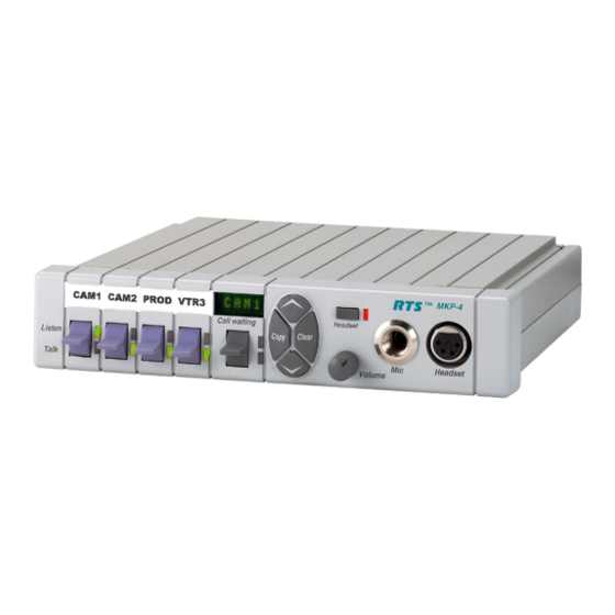
Page 8: Front Panel Description
FRONT PANEL DESCRIPTION Intercom Keys: Assignable for several types of operation, including talk only, listen only, talk with auto-listen, and all-call (where activating the key also activates all keys to the left of that key). Keys feature momentary or latching operation. For momentary operation, the operator presses and holds a key while communicating, then releases it when finished. - Page 9 Figure 1.1 MKP-4 Front Panel View Figure 1.2 BKP-4, TKP-4, WKP-4 Front Panel View ™ WKP-4 Listen Talk Figure 1.3 MKP-12 Front Panel View Headset Call waiting Copy Clear Volume Headset...
-
Page 10: Back Panel / Circuit Board Switches And Connectors
BACK PANEL / CIRCUIT BOARD SWITCHES AND CONNECTORS BKP-4: Universal Power Input: Accepts any mains voltage from 90-240 VAC, 47-63 Hz. TKP-4 and WKP-4: Terminals for DC power connection. Intercom Frame Connectors. All units have both 9-pin female D-sub (DE9S) and RJ12 connectors. - Page 11 Figure 1.5 BKP-4 Rear Features Figure 1.6 WKP-4 & TKP-4 Configuration Switches and Connectors on Circuit Board (WKP-4 Shown) Figure 1.7 MKP-12 Rear Panel View...
-
Page 12: Specifications
SPECIFICATIONS Matrix Input/ Output 8 dBu nominal, 20 dBu maximum Audio Performance SNR at 8 dBu (A-weighted): > 70 dB THD+N at 8 dBu (Unweighted): < 0.5% Frequency Response at 8 dBu: ± 1.5 dB from 100 Hz - 10 kHz CMRR: >... - Page 13 WKP-4 Mounting Box: See Figure. TKP-4: 5.2" (132mm) high x 8.38" (213mm) wide x 3.25" (83mm) deep behind front panel. BKP-4: 4.6" (117mm) high x 9" (229mm) wide x 7" (178mm) deep Finish MKP-4, MKP-12: Thermoplastic front panel, aluminum case, light gray finish...
- Page 14 This page intentionally left blank. U s e r I n s t r u c t i o n s M K P - 4 , B K P - 4 , W K P - 4 , T K P - 4 , a n d M K P 1 2 K e y p a n e l s...
-
Page 15: Unpacking And Inspection
The container should include the following items (as listed by model): Models MKP-4, MKP-12, BKP-4 Keypanel (model MKP-4, MKP-12, or BKP-4 depending on model ordered) IEC Power Cord User Manual Model TKP-4... -
Page 16: Wkp-4 Box Installation
WKP-4 BOX INSTALLATION If the WKP-4 was supplied assembled to the mounting box, remove the four (4) screws from the front panel. Mount the box in a suitable size wall opening using appropriate mounting screws (not supplied). Route the intercom and power wires into the box. Reinstall the front panel after all dip switch settings and connections are completed as described on the following pages. -
Page 17: Configuration Switches
CONFIGURATION SWITCHES If you change any configuration switch settings during operation, you must momentarily turn off Important! power to reset. DIP Switches DIP Switch 1 Open: Default setting. All incoming calls appear in the call waiting display (if present). Closed: Only calls for unassigned callers appear in the call waiting display (if present). Description: Any intercom key that is already assigned to talk/listen to a specific intercom port will always provide an LED flash for incoming calls from that port. -
Page 18: Dip Switch 6
Incoming audio is enabled as soon as the talk key is released. This application is seldom used. DIP Switch 8 Open: Default setting for MKP-4, BKP-4, TKP-4 and WKP-4. Map keys as xKP-4 series. Closed: Default setting for MKP-12. Map keys as MKP-12. - Page 19 Then, read across to the “Address” column to find the Address number. Set the keypanel Address switch to this number. The MKP-4, BKP-4, TKP-4, WKP-4 and MKP-12 keypanels can support ADAM systems up to Important! two frames in size Table 2.1...
- Page 20 U s e r I n s t r u c t i o n s M K P - 4 , B K P - 4 , W K P - 4 , T K P - 4 , a n d M K P 1 2 K e y p a n e l s...
-
Page 21: Mounting The Mkp-4
MOUNTING THE MKP-4 The MKP-4 can be used on a desktop, console mounted, or rack mounted. Some possible mounting configurations and the required optional mounting hardware are shown in Figure 2.1. When mounting the MKP-4, always allow adequate room behind the unit for cable access. There are no special ventilation requirements. -
Page 22: Connections
CONNECTIONS Mic Connector To connect a panel microphone, such as the RTS model MCP90, screw the microphone into the Mic connector on the front panel of the keypanel. For Mic connector specifications, see “SPECIFICATIONS” in Section 1. NOTE Headset Connector The Headset connector accepts a monaural, dynamic-microphone headset (headphones and microphone). -
Page 23: Bkp-4 Connection
TO KEYPANEL TO INTERCOM SYSTEM* DATA AUDIO TO MATRIX AUDIO FROM MATRIX CABLE TYPE: BELDEN 8777 IMPORTANT! When connecting to an ADAM CS back panel, use only low-profile cable connectors such as AMP Part No. 747516-3 (Telex Part No. 59926-678) -
Page 24: Tkp-4 / Wkp-4 Connection
Figure 2.5. Power Connection MKP-4, MKP-12, and BKP-4: Plug an power cord (not supplied) into the power connector and into any 90-240 VAC, 47-63 Hz main power source. TKP-4 / WKP-4: Connect an optional AC adapter using the color-code information on the AC adapter and the terminal pinout information in Figure 2.4. -
Page 25: Startup And Operational Check
STARTUP AND OPERATIONAL CHECK When power is applied, all LEDs will first flash red, then green. This confirms that all LEDs are working correctly. Also, the call waiting window will display asterisks (****) then dashes (----). Figure 2.6 Call Waiting Window (CWW) and Key If the keypanel cannot establish data communications with the intercom system, asterisks will NOTE continue to display. - Page 26 2-12 U s e r I n s t r u c t i o n s M K P - 4 , B K P - 4 , W K P - 4 , T K P - 4 , a n d M K P 1 2 K e y p a n e l s...
-
Page 27: Assigning Intercom Keys
ASSIGNING INTERCOM KEYS You can assign keypanel intercom keys using ZEUSedit or ADAMedit. For help with key assignment in ZEUSedit or ADAMedit, click the KP button on the program's toolbar, then press the F1 key on the computer keyboard for help. If your keypanel has Copy, Clear, and Scroll buttons, you can also assign keys at the keypanel, with the following exceptions: Special functions (auto follow, auto listen, etc.) cannot be assigned. -
Page 28: Clearing Key Assignments
To select a particular scroll list, tap the Copy button. You can go through the names in the selected scroll lists by tapping the Scroll Up or Scroll Down button. Tap the CWW key up to return to normal operation. •... - Page 29 Tap the Scroll Up or Scroll Down button to select the desired setup page. Tap the Copy button to assign the selected setup page. The topmost LED next to the call waiting key will flash briefly to confirm the assignment.
- Page 30 This page intentionally left blank. U s e r I n s t r u c t i o n s M K P - 4 , B K P - 4 , W K P - 4 , T K P - 4 , a n d M K P 1 2 K e y p a n e l s...
-
Page 31: Headset Button Operation
HEADSET BUTTON OPERATION Operation of the Headset button depends on the position of DIP switch 4 on the back panel (see Section 2). DIP switch 4 in Open position (default) • Startup Settings: The panel mic connector (Mic) and the speaker will both be on. The Headset connector will be off. -
Page 32: Intercom Key Operation
INTERCOM KEY OPERATION Momentary vs. Latching Operation For momentary key activation, press and hold an intercom key. For latching operation, tap the key to turn it on, and tap it again to turn it off. • If the LED next to a key does not turn on when the key it activated, this means the key is not NOTES currently assigned. -
Page 33: Listen Indicator
is equipped with optional trunking). The “in-use” indication warns you that someone else is currently talking. • Red flashing “busy” indication: May occur when a key is activated to talk to an IFB or a remote intercom system. This indicates that some other keypanel with a higher priority is currently talking and you cannot talk at this time. -
Page 34: Displaying Key Assignments
1, N002 indicates port 2 and so forth. SIDETONE ADJUSTMENT When you use the MKP-4, MKP-12, BKP-4, TKP-4 or WKP-4 with a headset, your own voice audio can be heard in the headphones. This is especially helpful when using headphones that completely cover the ears, because it eliminates the muffled sensation when talking.
Need help?
Do you have a question about the BKP-4 and is the answer not in the manual?
Questions and answers