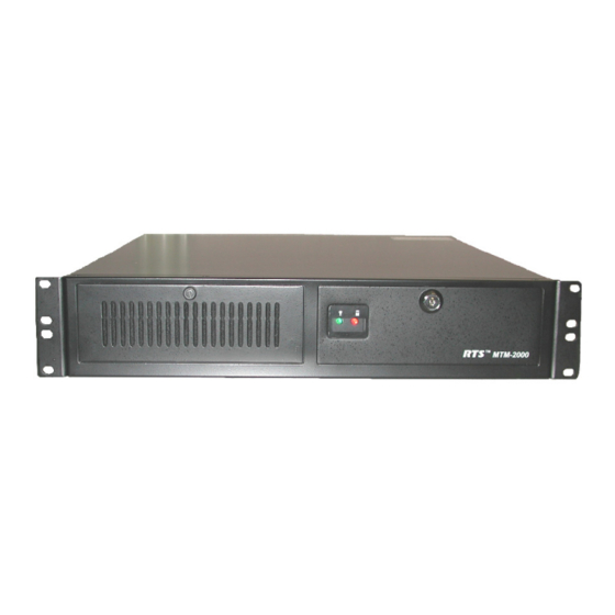
RTS ICP-2000 User Manual
Trunk master mini-trunk master switch over panel interconnect panel intelligent trunking system
Hide thumbs
Also See for ICP-2000:
- User manual (28 pages) ,
- User manual (32 pages) ,
- User manual (15 pages)
Summary of Contents for RTS ICP-2000
- Page 1 User Manual Model TM-2000 Trunk Master MTM-2000 Mini-Trunk Master SWP-2000 Switch Over Panel ICP-2000 Interconnect Panel Intelligent Trunking System TM-2000 MTM-2000 9350-7715-000 REV D. 06/2004...
- Page 2 This page intentionally left blank...
- Page 3 PROPRIETARY NOTICE The RTS product information and design disclosed herein were originated by and are the property of Telex Communications, Inc. Telex reserves all patent, proprietary design, manufacturing, reproduction, use and sales rights thereto, and to any article disclosed therein, except to the extent rights are expressly granted to others.
- Page 4 This page intentionally left blank...
-
Page 5: Table Of Contents
Contents Introduction ... 6 TM-2000/MTM-2000 Description ... 6 Front Panel Features ... 6 Rear Panel Features ... 6 ICP-2000 Description ... 7 Front Panel Features ... 7 SWP-2000 Description ... 7 Understanding Trunking ... 8 Installation ... 8 Rack Mounting ... 9 Trunking Connections and Setup ... - Page 6 This page intentionally left blank...
-
Page 7: Introduction
Introduction This manual describes the installation and opera- tion of the TM-2000/MTM-2000 Trunk Master and Mini-Trunk Master, SWP-2000 Switch Over Panel, and ICP-2000 Interconnect Panel. TM-2000/MTM-2000 Description The RTS Trunking System manages intercommu- nications between separate intercom systems using intercom ports that have been reserved and interconnected between the intercom systems. -
Page 8: Icp-2000 Description
ICP-2000. For ex- ample: If the cable plugged into an ICP-2000 with ports 1-8 on it, then J1 would be port 1, J2 port 2, up to J8 being port 8. -
Page 9: Understanding Trunking
System B and System C to do so, because that would require two levels of cascade. Installation Unpacking Please report any damage to the shipper or Telex immediately. Installing Software There are two software packages that can be used with an external PC connected to the TM-2000/MTM- 2000. -
Page 10: Rack Mounting
RS-485 communication cards/port numbers. See Figure 8 for an example of card/port labeling. Figure 9 depicts how the ports are mapped to the ICP-2000 panels. Caution: On most systems Port 1 can be used for trunking. On special systems that use Video Delegate Panels (VDP), Port 1 is reserved for use with VDP panels. - Page 11 NOTE: The number of trunk lines that you setup should be based on the number of persons that need to communicate with other intercom systems, and on the critical nature of their communication. On the other hand, there may be additional expense involved with running trunk lines (when using leased lines for example) and you will want to keep the number of lines to a minimum.
-
Page 12: Specifications
Height: ... 1.75” (44mm) Width: ... 19.0” (483mm) Depth: ... 5.3” (133mm) Weight: ... 5.2lbs (2.4kg) Power: ... 100-240 VAC, 47-63 ICP-2000 Height: ... 1.75” (44mm) Width: ... 19.0”” (483mm) Depth: ... 1.0” (25.4mm) Weight: ... 5.2lbs (2.4 kg) Environment Operating Temperature ... -
Page 13: Licensing For The Tm-2000/Mtm-2000
Licensing for the TM-2000/MTM-2000 In order for the TM-2000/MTM-2000 software to operate you must have either a signed license file or a USB dongle. If the dongle is used it must always be present and connected to the TM-2000/MTM-2000. When installing the TM-2000/MTM-2000 software, the computer will check for the presence of the a USB dongle. -
Page 14: Tm-2000/Mtm-2000 Software Installation Configuration Options
When the option to install the software is selected, the computer prompts for different pieces of information: Is the computer to be part of an active/standby configuration ? There are three choices: Stand-alone operation: Active/standby operation (Active by default): Active/standby (Standby by default): In addition the following parameters are set by default: Domain or Workgroup... - Page 17 Figure 12. 9-pin D-sub connector pintouts. Figure 16. RJ-45 Connector pinout. Figure 17. DE-9S to DE-9S audio cable Figure 13. 25-pin D-sub connector pinout Figure 14. 50-pin SCSI type II connector pinout Figure 18. DE-9s to unspecified device audio cable. Figure 15.
- Page 18 Figure 21. Unspecified device to RJ-11 audio cable. Figure 22. ICP-2000 to ADAM RS-485 data cable. Figure 23. ICP-2000 to ADAM CS RS-485 data cable. Figure 24. ICP-2000 to unspecified device RS-485 data cable. Figure 25. ADAM to unspecified device RS-485 data cable.
- Page 19 Figure 28. TM-2000 to SWP-2000 parallel port status and control cable. Figure 29. TM-2000 to ICP-2000 RS-485 COM ports.
- Page 20 Use an RS-232 wired “Straight Through” for SWP-2000 to TM-2000 connections. Use a RS-232 wired “Null Modem” for PC to TM-2000/SWP-2000 connections. For TM-2000 to ICP-2000, RS-485 cables use the supplied cables. For TM-2000 to SWP-2000 status/control cables use 25 conductor shielded cable. DO NOT EXCEED 10...
-
Page 21: Appendix A - Useful Linux Tricks
Appendix A Useful Linux Tricks On the computer console, Shift-Page Up and Shift-Page Down can be used to scroll through the last 6 or so screenfuls of text. Each keystroke scrolls forward and back by half of a screen. The TM-2000/MTM-2000 is configured with 2 virtual consoles. Normally, everything is done on the first virtual console.


Need help?
Do you have a question about the ICP-2000 and is the answer not in the manual?
Questions and answers