
Related Manuals for Akai DPS16


Summary of Contents for Akai DPS16
- Page 1 DIGITAL PERSONAL STUDIO WARNING To prevent fire or shock hazard, do not expose this appliance to rain or moisture. Operator’s Manual...
- Page 2 WARNING!! To prevent fire or shock hazard, do not expose this appliance to rain or moisture. 1-En CAUTION RISK OF ELECTRIC SHOCK DO NOT OPEN CAUTION: TO REDUCE THE RISK OF ELECTRIC SHOCK, DO NOT REMOVE COVER (OR BACK). NO USER-SERVICEABLE PARTS INSIDE. REFER SERVICING TO QUALIFIED SERVICE PERSONNEL.
- Page 3 Use only a household AC power supply. Never use a DC power supply. • If water or any other liquid is spilled into or onto the DPS16, disconnect the power, and call your dealer. • Make sure that the unit is well-ventilated, and away from direct sunlight.
- Page 4 WARNING WARNING THIS APPARATUS MUST BE EARTHED IMPORTANT This equipment is fitted with an approved non-rewireable UK mains plug. To change the fuse in this type of plug proceed as follows: 1) Remove the fuse cover and old fuse. 2) Fit a new fuse which should be a BS1362 5 Amp A.S.T.A or BSI approved type. 3) Refit the fuse cover.
- Page 5 27-F COPYRIGHT NOTICE The AKAI DPS16 is a computer-based device, and as such contains and uses software in DISKs and ROMs. This software, and all related documentation, including this Operator’s Manual, contain proprietary information which is protected by copyright laws. All rights are reserved. No part of the software or its documentation may be copied, transferred or modified.
- Page 6 If the warranty is valid, AKAI professional will, without charge for parts or labor, either repair or replace the defective part(s). Without a valid warranty, the entire cost of the repair (parts and labor) is the responsibility of the product's owner.
-
Page 7: Table Of Contents
Connecting a device that has digital output jacks ..........21 Connecting an external effect unit ..............21 Preparing to record ......................22 Turning on the power to the DPS16 ................. 22 Formatting a hard disk ..................... 22 Creating a new Project .................... 24 Recording the first track .................... - Page 8 Mixdown ........................36 Signal flow during mixdown ..................36 Mixdown procedure ....................37 Using Mixer mode ......................37 Completing operations on the DPS16 ................39 Chapter 3: Transport/Locate Operation ........40 Using the transport functions ..................40 Transport buttons ..................... 40 Using the [JOG] wheel/[SHUTTLE] knob ..............
- Page 9 Table of contents Chapter 5: Assigning Input Signals and Tracks (Quick Patch mode and V. Track mode) ....53 Main Quick Patch mode screen ..................53 Basic operations in Quick Patch mode ................54 Assigning recording sources to physical tracks ............54 Patching (assigning) a recording source to a single track ........
- Page 10 Table of contents Using the Solo and Mute functions ................. 86 Solo function ......................86 Mute function ......................87 Digital input from an external device ................88 Applying EQ while recording ..................90 Chapter 8: Edit Technique (Edit Mode) ........91 Using an Edit mode screen .....................
- Page 11 Synchronizing the DPS16 to an external device (MTC) ..........137 Controlling the DPS16 remotely from an external device (MMC) ........138 Recording and playing the DPS16’s snapshot on a MIDI sequencer ......139 Recording and playing back a mix automation ............. 141 DPS16 MIDI Control Change Assign Table ............
- Page 12 Table of contents XOVER CHORUS ....................158 MONO FLANGER ....................159 STEREO FLANGER ....................159 XOVER FLANGER ....................160 PAN FLANGER ...................... 160 MONO PHASER ....................161 STEREO PHASER ....................161 XOVER PHASER ....................162 PAN PHASER ......................162 PITCH SHIFT ......................163 ROTARY SPEAKER ....................
-
Page 13: Chapter 1: Overview Of The Dps16
• The DPS16 has an internal IDE hard disk and allows you to connect up to six SCSI devices (such as external hard disks and MO drives) to the SCSI connector on the rear panel for recording and data backup. Connecting a CD-R/RW drive that supports Multi-Media Commands (MMC) enables you to write audio tracks of the DPS16 to a CD-R/RW disc. -
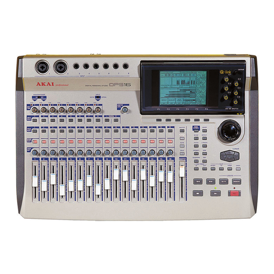
Page 14: Parts And Functions
NOTE : [PHANTOM POWER] lowered or the power to the DPS16 is turned off. 3 GUITAR/NORMAL switch This switch enables you to select input impedance for Input 8. Turn this switch to GUITAR to connect a high- impedance electric guitar, and turn this to NORMAL to connect a low-impedance microphone or line-level device. - Page 15 PHONES jack. CONTRAST SHUTTLE M Display This LCD display indicates various information required for operating the DPS16, such as the time counter, level meter, and mix parameter settings. N [CONTRAST] knob Enables you to adjust the display contrast.
- Page 16 Chapter 1: Overview of the DPS16 MAIN MIXER MASTER SCREEN SETUP EFFECT NUMBER /NAME PATCH V.TRACK MUTE CURSOR PROJECT DISK SOLO WAVEFORM EDIT MASTER EDIT POINT PLAY IN-OUT FROM UNDO LOCATE MEMORY GO TO S [CURSOR] key The cursor key is used to move the cursor (highlighted part) on the display to select an item.
-
Page 17: Front Panel
Z Point play key ([IN-OUT] key/[TO] key/[FROM] key) These keys are used to play back data between the IN and OUT points or to play for a specified duration around the current position of the DPS16. a [UNDO] key This key is used to cancel the recording or editing operation you just performed. When you press this key right... -
Page 18: Rear Panel
This connector transmits sync signals and control signals to an external device, such as a MIDI sequencer. If you change the setting for this connector on the DPS16, this connector functions as a MIDI THRU connector that outputs information received at the MIDI IN connector as it is. -
Page 19: Internal Ide Hard Disk
DPS16. (See page 22 for more information on how to format the disk.) • Before you turn off the power to the DPS16, make sure that the hard disk is not being accessed. If you turn off the power to the DPS16 while the hard disk is being accessed, the hard disk may be damaged and data on the disk may be lost. -
Page 20: Connecting Multiple Scsi Devices
• Use a short, high-quality SCSI cable, if possible. Using a cable that is too long or of low quality may cause an error. • You need to format the disk before you can use an external hard disk or MO drive connected to the DPS16. (Refer to pages 22 for more information on how to format the disk.) •... -
Page 21: Terminology And Functions Unique To Dps16
Terminology and functions unique to DPS16 The DPS16 is a product that integrates a hard disk recorder, digital mixer, and a digital effects processor. From recording to output at the MASTER OUT jack, all data is processed in the digital domain. Therefore, its concept and the way in which it works is slightly different than conventional MTRs or analog mixers. -
Page 22: Sampling Frequency And Bit Resolution
“bit resolution” indicates how precisely the audio signal is measured. On the DPS16, you can specify a sampling frequency (32, 44.1, 48, or 96kHz) and a bit resolution (16-bit or 24- bit) for each Project. Depending on these settings, the number of tracks available for simultaneous recording and playback varies. -
Page 23: Track Mix Channels And Input Mix Channels
TRACK MIX channels and INPUT MIX channels The DPS16’s mixer section offers ten channels (called “INPUT MIX channels”) that enable you to control input signals that come directly from INPUT jacks 1–8 and the DIGITAL IN jack, as well as sixteen channels (called “TRACK MIX channels”) for which you can control track playback signals from the recorder section. - Page 24 Chapter 1: Overview of the DPS16 4 The master level of the stereo mix signal is adjusted by the master fader on the top panel. This signal is output from the MASTER OUT jacks (analog) and the DIGITAL OUT jack (digital).
- Page 25 Chapter 1: Overview of the DPS16 3 The stereo mix signals of the INPUT MIX channels and TRACK MIX channels are adjusted for the master level by the master fader on the top panel, then output from the MASTER OUT jacks (analog) and the DIGITAL OUT jack (digital).
-
Page 26: Scene Memory
Scene memory The DPS16 can store a set of mix parameter settings as a scene, and recall the scene later. A scene is stored as part of the Project on the disk. You can store up to 8 scenes in one Project. For example, you may store multiple scenes with different balance and EQ settings for mixdown, and audition and compare different mixes. - Page 27 Chapter 1: Overview of the DPS16 The Main screen shows the following information: Project Indicates the name of the Project you are currently working on (current Project). Remain Indicates the remaining time available for recording on the disk in hours/minutes.
-
Page 28: Changing The Settings And Values
Chapter 1: Overview of the DPS16 Changing the settings and values You can either use the [JOG] wheel or enter a numeric value directly to change the settings or time values of the fields and the time counter. Using the [JOG] wheel to change the settings Use the wheel to change the time value of the time counter or the field settings. -
Page 29: Entering Characters
Chapter 1: Overview of the DPS16 Entering characters You can either select a character using the [JOG] wheel or type a character directly to enter characters in the character fields (for naming virtual tracks or Projects). Using the [JOG] wheel to enter characters 1. -
Page 30: Qlmc (Q-Link Mixer Control)
When the Main screen or a Mixer mode screen is displayed, the QLMC (Q-Link Mixer Control) section appears on the right side of the display. QLMC is a function used to directly control the DPS16’s mix parameters and effect parameters. -
Page 31: When The Qlmc Mode Is Set To Mixer
Chapter 1: Overview of the DPS16 When the QLMC mode is set to MIXER: Pressing the key repeatedly toggles the following two options: [F6] • ....Enables you to adjust the center frequency ( ) and the boost/cut amount (... -
Page 32: Chapter 2: Recording On The Dps16
Chapter 2: Recording on the DPS16 Chapter 2: Recording on the DPS16 This chapter describes the basic operations of the DPS16, including recording preparation, recording the first part, overdubbing, and mixing down to a master recorder. Connections The diagram below is an example of the basic connections for recording on the DPS16. -
Page 33: Connecting Sound Sources
Connecting an external effect unit To use external effects, such as reverb and delay, connect the AUX SEND 1–4 jacks of the DPS16 to the input jacks of the external effect unit, and the output jacks of the effect units to the input jacks of the DPS16. -
Page 34: Preparing To Record
Formatting a hard disk Before you use the DPS16 or a connected removable drive, such as an external hard disk or MO disk for the first time, format the disk and media following the steps below. (Ignore this procedure if you use a pre-formatted disk.) 1. - Page 35 This Disk List screen indicates the status of the internal hard disk and the external drive connected to the SCSI bus. In this example, the ATA field indicates the internal hard disk and the SCSI ID 6 field indicates the DPS16.
-
Page 36: Creating A New Project
You can create a new Project using the Create New Project window. This window appears when you press the ) key after the disk is formatted or after you press the key to place the DPS16 in Project [F5] [PROJECT] mode. -
Page 37: Recording The First Track
Track 15 Track 16 1 With the DPS16’s default settings, signals input at INPUT jacks 1 and 2 are sent via the [INPUT TRIM] knobs to physical tracks 1 and 2 of the recorder section. 2 Press [RECORD SELECT] keys 1 and 2 on the top panel to cause tracks 1 and 2 to enter record- ready status. -
Page 38: Recording To The First Track
(and their LEDs flash in red), the corresponding tracks enter [RECORD SELECT] record-ready mode. The type of signal output from each track varies depending on the status of the DPS16 and the status of the key for each track. - Page 39 9. Press the [ ] button to start playback from the top of the song. When the DPS16 plays back data, you can monitor the recorder’s playback sound through any track, regard- less of the on/off status of their [RECORD SELECT] keys.
-
Page 40: Using Locate Points
(this operation is called “locating”). The DPS16 offers “Direct locate” points that can be assigned to the keys on the top panel, as well as normal locate points that can be named and stored in a list. - Page 41 Chapter 2: Recording on the DPS16 5. To locate the stored direct locate point, press the [GO TO] key when the DPS16 is stopped. The Shortcuts window and the Locate List window appear where you can perform the locate operation.
-
Page 42: Overdubbing
Chapter 2: Recording on the DPS16 Overdubbing “Overdubbing” is a recording operation in which you record another part in a new track while monitoring the playback sound from tracks that have already been recorded. In this example, we overdub a bass guitar sound from INPUT jack 8 to track 3 while listening to the rhythm machine recorded on tracks 1 and 2. -
Page 43: Overdub Operation
INPUT jack 8 accepts high-impedance instruments. You can connect an electric guitar or bass directly to this input. 2. Press the [PATCH] key The DPS16 enters Quick Patch mode in which you can change the internal routing, and displays the following Quick Patch screen. Input This field indicates the destinations of the signals input from the INPUT jacks (1–8) and DIGITAL IN jack. - Page 44 ”. SOURCE When you play the DPS16, you can monitor the input source through the record-ready track (not the track playback sound). For example, while listening to the track playback sound (tracks 1 and 2 in this example) and the input signal through the record-ready track (the bass sound in this example), you can practice your perfor- mance.
-
Page 45: Using The Undo/Redo Functions
If you are not satisfied with a recording, you can use the Undo function to cancel the previous recording. With the DPS16’s default setting, the undo level is set to “1”. (The undo level is a parameter that determines the number of previous operations you can undo. -
Page 46: Punch In/Out
The Punch In/Out function enables you to re-record only a specified region on a track that has already been recorded. The DPS16 offers a “Manual Punch In/Out function” that uses the transport buttons and a foot switch, and an “Auto Punch In/Out function” that automatically performs the punch in/out operation at specified posi- tions. - Page 47 [REC] button’s LED lights up, and the record-ready track starts recording. • When the time counter value reaches the OUT point: button’s LED turns off and the DPS16 automatically resumes playback. [REC] 11. Press the [ ] button to stop playback.
-
Page 48: Mixdown
Chapter 2: Recording on the DPS16 Mixdown You can repeat the steps described thus far to record up to sixteen tracks. However, this does not mean that you now have a completed work. Next, you will need to set the level and pan for each recorded track, and record the data onto a connected DAT tape recorder or cassette tape recorder. -
Page 49: Mixdown Procedure
2. Turn off all of [RECORD SELECT] keys 1–16. 3. Play back the song from the beginning on the DPS16, and adjust the channel faders, the [TRACK PAN] knobs, and the master fader to appropriate positions. At this time, you can check the output levels of the tracks and the output level of the Master L/R by observing the level meters on the Main screen. - Page 50 Chapter 2: Recording on the DPS16 • (equalizer on/off) EQ ON/OFF • EQ HIGH FREQ (center frequency in the high range) • EQ HIGH LEVEL (boost/cut amount in the high range) • EQ MID FREQ (center frequency in the middle range) •...
-
Page 51: Completing Operations On The Dps16
2. Make sure that the DPS16’s internal hard disk and the external drive are not accessed. Turn off the power to the DPS16. Use the Disk Busy field on the Main screen to check to see whether or not the disks are being accessed. -
Page 52: Chapter 3: Transport/Locate Operation
This chapter describes the transport and locate operations of the DPS16. Using the transport functions The DPS16 enables you to perform normal transport operations, such as playback, recording, and fast rewind, as well as jog playback using the wheel and shuttle playback using the knob. - Page 53 Chapter 3: Transport/Locate Operation 1. Press the [WAVEFORM] key. The DPS16 enters Waveform mode and displays the following screen. 1 Displays the audio waveform of the currently selected track. 2 [F3] ( ) key ZOOM 3 [F4] ( ) key ZOOM These function keys are used to zoom the waveform in and out vertically.
-
Page 54: Using The [In-Out] / [To] / [From] Keys
IN-OUT FROM UNDO [TO] key [FROM] key The DPS16 plays a section for a few seconds up to the current time, or a section for a few seconds from the current time, when you press the [TO] key or [FROM] key respectively while the transport section of the DPS16 is stopped. -
Page 55: Locate Operation
You may specify up to 100 points (locate points) in a song and store them to help you locate points quickly. The DPS16 also features a Direct Locate function that enables you to assign a locate point to a key on the panel and locate the point with a simple key operation. -
Page 56: Locating The End Point Of A Song
• You may also specify a locate point in bar/beat/clock by moving the cursor to the BBC counter field. This is useful when the DPS16 is synchronizing the MIDI sequencer. See page 134 for more information. -
Page 57: Storing Locate Points
[MEMORY] key 1. Press the [MEMORY] key at the position you wish to store the desired point. You may store locate points while the DPS16 is recording, playing, or stopped. When you press the [MEMORY] key again, the next Locate Memory window opens, indicating the time value in the... -
Page 58: Deleting A Locate Point From The Locate List
1. Press the [MEMORY] key to capture the desired locate point. You may store locate points while the DPS16 is recording, playing, or stopped. When you press the key, the following Locate Memory window opens, indicating the time value in the... -
Page 59: In Point And Out Point
Storing direct locate points to the [IN]/[OUT] keys 1. Press the [MEMORY] key to capture the desired locate point. You may store locate points while the DPS16 is recording, playing, or stopped. When you press the [MEMORY] key, the next Locate Memory window opens, indicating the time value in the... -
Page 60: Using The Stored Direct Locate Points
IN point, and the data between the IN and OUT points is repeatedly played. If you start playing back from a position after the OUT point, the DPS16 locates the IN point first, then starts... -
Page 61: Chapter 4: Punch In/Out
Manual Punch In/Out is to perform the punch in/out operation manually. You may use the transport buttons on the DPS16 or a connected foot switch to use this function. Using a foot switch is useful when you are playing instruments with both hands. -
Page 62: Punch In/Out Operation Using A Foot Switch
DPS16, when you turn on the power to the DPS16, it automatically detects the type of foot switch connected. You can use either type of foot switch. If a foot switch is not connected to the DPS16, when you turn on the power to the DPS16, it automatically selects normal open mode. -
Page 63: Auto Punch In/Out
If the REHEARS parameter for the Auto Punch function of Q-Link Function Select has been turned on, the DPS16 enters “Rehearsal mode” in which you can practice the punch in operation before you record a real punch in take. Refer to page 100 for more information. -
Page 64: Punch In/Out Rehearsal
Chapter 4: Punch In/Out Punch In/Out Rehearsal Rehearsal is a function that enables you to practice playing instruments or singing a song, pretending to punch in/ out record, but nothing is actually recorded. This is useful when you wish to practice the punch in/out timing and check the range of auto punch in/out. In this section, we offer the example of rehearsing the manual punch in/out operation and explain how to use the Re- hearsal function. -
Page 65: Chapter 5: Assigning Input Signals And Tracks (Quick Patch Mode And V. Track Mode)
Main Quick Patch mode screen When the DPS16 is set to default, signals input (for example) at INPUT jacks 1 and 2 are routed to tracks 1 and 2. In Quick Patch mode, you can change signal routings. For example, you can send INPUT 1 and 2 signals to tracks 3 and 4, or directly to the mixer’s master section. -
Page 66: Basic Operations In Quick Patch Mode
Basic operations in Quick Patch mode Assigning recording sources to physical tracks When the DPS16 is set to default, the signals from INPUT jacks 1–8 and DIGITAL IN jacks are routed to physical tracks 1–16. However, you can select any recording source for each track. -
Page 67: Canceling The Patch
Chapter 5: Assigning Input Signals and Tracks NOTE : When you select the input signal as the recording source, make sure that the input signal is routed to the Source section on the Quick Patch screen (that is, a thick line is descending). Even if you select the input signal (an ascending thick line) sent directly to the master section, it will not be sent to any tracks. -
Page 68: Routing Input Signals Directly To The Mixer's Master Section
26 channel signals (16-track playback signals and 10 channel input signals). If you are using an external effect unit via the AUX out, you can mix the playback sound from the DPS16 and the effect sound from the external effect unit by returning the effect signals from the effect unit to the input jacks of the DPS16 and routing the input signals directly to the mixer section. -
Page 69: Erasing The Patch
Chapter 5: Assigning Input Signals and Tracks Erasing the patch To erase the patch, press the CLEAR ) key in Quick Patch mode. [F4] As shown below, all patches that connect the recording sources in the Source section and physical tracks will be cancelled. -
Page 70: Selecting Output Signals
Selecting output signals You can select any signal output from the MASTER OUT jacks, AUX SEND 1–4 jacks, and DIGITAL OUT jack in Quick Patch mode. 1. While the DPS16 is in Quick Patch mode, press the [F2] ( ) key. OUTPUT The following Output Terminal screen appears, where you can assign signals to each output jack. -
Page 71: Resetting The Output Signal Assignment To The Default Setting
Resetting the output signal assignment to the default setting Reset the output signal assignment to the default setting as follows. 1. While the DPS16 is in Quick Patch mode, access the Output Terminal screen and press the [F6]( DEFAULT key. -
Page 72: Main V. Track Mode Screen
Main V. Track mode screen The DPS16 offers two types of tracks: physical tracks and virtual tracks. Virtual tracks are used to store audio data. Unless you assign them to physical tracks, you cannot record or edit in virtual tracks. In V. Track mode, you can assign virtual tracks to physical tracks. -
Page 73: Basic Operations In V. Track Mode
Basic operations in V. Track mode Follow the steps below to assign virtual tracks to physical tracks. 1. While the DPS16 is in V. Track mode, move the cursor to the physical track (1–16) field for which you wish to change the assignment. -
Page 74: Chapter 6: Mixer Function (Mixer Mode)
[F2] CHANNEL key to access this page. Global page This page enables you to make settings for the entire mixer section of the DPS16 (see page 71). Press the GLOBAL ) key to access this page. [F3] Scene Memory page This page enables you to store and recall a scene that contains the mix parameter settings (see page 73). -
Page 75: Control View Page
Chapter 6: Mixer Function (Mixer Mode) Control View page Pressing the ) key while holding down the key or while the Channel View page is [F1] CONTROL [MIXER] displayed will access the Control View page, which displays the currently selected mix parameters for all chan- nels. -
Page 76: Mix Parameters On The Control View Page
Chapter 6: Mixer Function (Mixer Mode) 2. Use the [CURSOR] key to move the cursor to the field, and turn the [JOG] wheel to select Control a mix parameter. <ex. The Pan parameter is selected.> This parameter is set to “ ”... -
Page 77: Pan
Chapter 6: Mixer Function (Mixer Mode) You can adjust the stereo image for the channels. Range: R63 – 0 – L63 You can also use the controls on the top panel to adjust the pan setting for TRACK MIX channels. TIP : [PAN] NOTE :... -
Page 78: S1 Route - S4 Route (Send 1-4 Routing)
Chapter 6: Mixer Function (Mixer Mode) S1 ROUTE – S4 ROUTE (Send 1–4 routing) You can select how the signals of each channel are sent to AUX send 1–4 or the internal effects (FX 1–4). Range: PRE/POST/INSERT The parameter settings are as follows: •... -
Page 79: Send1 Lev - Send4 Lev (Send Level 1-4)
Chapter 6: Mixer Function (Mixer Mode) SEND1 LEV – SEND4 LEV (Send level 1–4) You can set the level of channel signals sent to AUX send 1–4 and the master level of AUX send 1–4. Range: 0 – 127 TIPS : •... -
Page 80: Eq On/Off
Chapter 6: Mixer Function (Mixer Mode) NOTE : The number of AUX SENDs you can use simultaneously varies depending on the sampling rate setting. The number of effects you can use simultaneously is also affected in the same way. If the sampling rate is 32kHz, 44.1kHz, or 48kHz, you can use up to four AUX SENDs (and effects). -
Page 81: Eq High L/Eq Mid L/Eq Low L (Eq Level)
Chapter 6: Mixer Function (Mixer Mode) EQ HIGH L/EQ MID L/EQ LOW L (EQ level) You can set the boost and cut amounts for each EQ band. Range: –12dB – +12dB TIP : You can also use the QLMC knobs on the top panel to control the boost/cut amount. See page 19 for more information. -
Page 82: Channel View Page
Chapter 6: Mixer Function (Mixer Mode) Channel View page Pressing the ) key while the Control View page is displayed accesses the Channel View page, [F2] CHANNEL which indicates all mix parameters for the currently selected channel (or master section). This page is useful when you wish to focus on a particular channel. -
Page 83: Master Section View
[JOG] Master out This field enables you to select the digital output level of the DPS16 from among 0dB, +6dB, and +12dB. This setting affects the output signals from the MASTER OUT jack, the MONITOR OUT jack and the PHONES jack. - Page 84 MIDI window in Mixer mode. (see page 107) All MIDI data received at the MIDI IN connector will be output from the MIDI OUT/THRU connector regardless of this parameter setting. • To record and play back the mixer operation of the DPS16 to and from the MIDI sequencer, set this parameter to “...
-
Page 85: Scene Memory Page
Chapter 6: Mixer Function (Mixer Mode) Scene Memory page While the Control View page or the Channel View page is displayed, pressing the ) key accesses the [F4] SCENE Scene Memory page, where you can store all mix parameters in Mixer mode as a “scene” and recall stored scenes. The following mix parameters can be stored as part of a scene. -
Page 86: Recalling A Scene
3. Press the [F3] ( ) key. RECALL The mix parameters of the DPS16 change to the settings of the selected scene, and the Mixer mode screen appears. NOTE : You cannot recall the current mixer settings once you recall the scene. If you need to recall the... -
Page 87: Erasing A Scene
You cannot use the Undo function for the erase operation. Make sure that you have selected the correct scene to erase. Controlling the mix parameters using the QLMC section While the DPS16 displays the main screen or Mixer mode screen, the QLMC (Q-Link Mixer Control) section appears on the right of the display. - Page 88 Chapter 6: Mixer Function (Mixer Mode) 2. Use the [INPUT SELECT] keys, [TRACK SELECT] keys, and [MASTER] key to select the desired channel. The following keys can be used to select a channel when the QLMC mode is set to “ MIXER ”.
- Page 89 Chapter 6: Mixer Function (Mixer Mode) • SEND • RETURN [F6] key FX 1 Return: Return level setting for internal effect 1 FX 2 Return: Return level setting Send 1 Master: Master level setting for Send 1 for internal effect 2 Send 2 Master: Master level setting for Send 2 FX 3 Return: Return level setting Send 3 Master: Master level setting for Send 3...
-
Page 90: Chapter 7: Advanced Technique For Mixing
Chapter 7: Advanced Technique for Mixing The DPS16 is designed for ease of operation from recording to mixdown, similar to a cassette multitrack recorder. It also enables you to combine various functions for more advanced mixing operations. This chapter introduces advanced techniques for mixing with the DPS16. - Page 91 Chapter 7: Advanced Technique for Mixing 2. Move the cursor to the field for track 16, then press the [NUMBER/NAME] key and name this virtual track “ ”. GUITAR SOLO1 Refer to page 17 for how to enter characters. 3. Return to the Main screen and record the first guitar solo take to Track 16. 4.
- Page 92 Chapter 7: Advanced Technique for Mixing You can also assign these recorded virtual tracks to multiple physical tracks. Track 1 GUITAR SOLO 1 Track 2 GUITAR SOLO 2 Track 3 GUITAR SOLO 3 Track 4 GUITAR SOLO 4 Track 5 GUITAR SOLO 5 In this way, you can use the edit commands (such as COPY →...
-
Page 93: Ping-Pong Recording
1–14 enable you to switch this parameter on and off very quickly. 4. Press the [PATCH] key. The DPS16 enters Quick Patch mode. In this mode, you need to change the patch (connection) so that the output signal from the ping-pong bus will be sent to track 15 and 16. - Page 94 The proper level cannot be monitored when the 15/16 channel faders are raised up at this time, since the bus sound are mixed together. 9. While playing the DPS16, use [TRACK PAN] knobs 1–14 and channel faders 1–14 to adjust the pans and levels of TRACK MIX channels 1–14.
-
Page 95: Mixing And Recording Several Input Signals
1. Connect the individual outputs of the rhythm machine to INPUT jacks 1–8 of the DPS16. 2. Press the [PATCH] key. The DPS16 enters Quick Patch mode. Here, you need to set the routing so that the input signals 1–8 are routed directly to the INPUT MIX channels in the mixer section. - Page 96 The proper level cannot be monitored when the 1/2 channel faders are raised up at this time, since the bus sound are mixed together. 10. Press the [MIXER] key to place the DPS16 in Mixer mode, and while playing the rhythm machine, adjust the pan, EQ, and level of INPUT MIX channels 1–8.
-
Page 97: Adding Sounds During Mixdown
1. Connect the synthesizer to INPUT jacks 1 and 2, and use [INPUT TRIM] knobs 1 and 2 to adjust the input levels. 2. Place the DPS16 in Quick Patch mode and set it so that Inputs 1 and 2 signals are sent to the mixer section. -
Page 98: Using The Solo And Mute Functions
Using the Solo and Mute functions The DPS16 provides a Solo function that allows specified channels to be routed to MONITOR OUT jacks, and a Mute function that allows specified channels to be muted. The Solo function is useful when you wish to monitor only certain channels without affecting the signals output from the MASTER OUT jacks and the DIGITAL OUT jack. -
Page 99: Mute Function
3. To exit the Mute function, press the [MUTE] key again. The DPS16 returns to the previous status. TIPS : You can use the Mute function in Mixer mode or Effect mode. When you press the... -
Page 100: Digital Input From An External Device
Digital input from an external device The DIGITAL IN jack on the rear panel of the DPS16 enables you to route digital audio signals output from the digital output jacks of a connected DAT or MD recorder, CD player, or sampler into the DPS16. In this example, we will record digital audio signals output from a connected DAT recorder onto tracks 1 and 2 of the DPS16. - Page 101 Chapter 7: Advanced Technique for Mixing 6. On the Quick Patch screen, route the input L/R signal (from the DIGITAL IN jack) to tracks 1 and 2 of the record track section. The input signal from the DIGITAL IN jack is now sent to physical tracks 1 and 2. 7.
-
Page 102: Applying Eq While Recording
1. Connect musical instruments or microphones to INPUT jacks 1 and 2, and set the input levels using the [INPUT TRIM] knobs. 2. Press the [QUICK PATCH ] key to place the DPS16 in Quick Patch mode, and assign INPUT 1 and 2 to physical tracks 1 and 2. -
Page 103: Chapter 8: Edit Technique (Edit Mode)
Chapter 8: Edit Technique (Edit Mode) The DPS16 provides various editing capabilities in Edit mode. You can specify a range of audio data in a track to copy to a different position. You can also delete the specified portion of data. For example, you may use the same chorus or guitar phrase repeatedly, or you may move all track data to a different position to change the structure of the song. -
Page 104: Basic Operations In Edit Mode
This operation is not necessary for the CUT → DISCARD, CUT → MOVE, TIME STRETCH, NOTE : STRETCH → MOVE edit commands. 3. Press the [EDIT] key. The DPS16 enters Edit mode and the Edit screen appears. Move the cursor to the Now time time, and time fields to fine-adjust the value, if necessary. -
Page 105: Type And Function Of Edit Commands
Chapter 8: Edit Technique (Edit Mode) If you select a command that enables you to edit a single track (such as INSERT SILENCE command), use the [RECORD SELECT] keys to select a track to be edited. 7. Set the , and other parameters, if necessary. Repeat times New length Refer to “Type and function of edit commands”... -
Page 106: Copy → Insert
Chapter 8: Edit Technique (Edit Mode) COPY → INSERT This command enables you to copy data between the IN and OUT points and insert it after the Now time (current position). The copy source data between the IN and OUT point will remain intact, and the existing data in the destination after the Now time will move forward in time. -
Page 107: Cut → Insert
Chapter 8: Edit Technique (Edit Mode) CUT → INSERT This command enables you to cut data between the IN and OUT points and insert it after the Now time (current position). The source data between the IN and OUT point will be replaced with silence, and the existing data in the destination after the Now time will move forward in time. -
Page 108: Cut → Move
Chapter 8: Edit Technique (Edit Mode) CUT → MOVE This command enables you to cut data between the IN point and OUT point. The data after the OUT point moves backward to the IN point. IN point OUT point Before edit After edit TIME STRETCH This command changes the length between the IN point and the OUT point. -
Page 109: Stretch → Move
Chapter 8: Edit Technique (Edit Mode) STRETCH → MOVE This command changes the length between the IN point and the OUT point. It does not change the pitch. If you stretch the region, the subsequent audio data moves forward by the amount of stretch. If you shorten the region, the subsequent audio data moves backward by the amount of shortening. -
Page 110: Chapter 9: Various Settings (Q-Link Functions, Setup Mode)
Chapter 9: Various Settings (Q-Link Functions, Setup Mode) Chapter 9: Various Settings (Q-Link Functions, Setup Mode) This chapter describes Q-Link functions and the operations in Setup mode used for the settings related to DPS16 operations. Q-Link Functions The DPS16 provides Q-Link functions that enable you to set various parameters of the DPS16 while the main screen is displayed. -
Page 111: What Q-Link Functions Offer
Sync/Clock function → page 100 • Setting the Vari Pitch function • Selecting the type of sync operation for the DPS16 and external devices (MTC master, MTC slave, MIDI clock master) • Selecting the clock source (internal clock, external clock) for DPS16 operation Track View function →... -
Page 112: Q-Link Functions
This parameter enables you to set the Repeat function on or off. Pressing the [F1] key toggles between . When this parameter is turned on, the DPS16 plays back data between the IN point and OUT point (specified by the keys) repeatedly. (See page 48 for more information on the Repeat function.) -
Page 113: Track View Function
2 This field enables you to select the type of sync operation of the DPS16 and the external device. Move the cursor to this field and turn the [JOG] wheel to select a type from the following four options. -
Page 114: Time Display Function
[F1] toggle between two options ( ABSO RELA • (absolute time) ....Absolute time referenced to the DPS16’s internal zero point ABSO 00:00:00:00.00 ) (default setting). • RELA (relative time) ....Relative time referenced to any zero point you set ( 00:00:00:00.00... -
Page 115: Setup Mode
The following settings are available in Setup mode. Setting a beat map (→ page 104) You can set the time signature information of a Project. Use the beat map to synchronize the DPS16 to the external MIDI sequencer via the MIDI clock. -
Page 116: Setting A Beat Map
MIDI sequencer may be out of sync with the playback sound of the DPS16. To avoid this, you need to enter the time signature information in the beat map. -
Page 117: Setting A Tempo Map
When an external device, such as a MIDI sequencer, synchronizes to the Song Position Pointer and the MIDI clock transmitted from the DPS16, the tempo settings of the MIDI sequencer are ignored and it runs by the tempo information from the DPS16. Therefore, you must specify the tempo of the MIDI clock on the DPS16 using the tempo map. -
Page 118: Other Settings
) key in Setup mode accesses the screen where you can set various parameters related to [F3] MISC. DPS16 operations. This section explains these parameters from the top of the screen. Project Setting This screen displays the sampling rate and data resolution of a Project. -
Page 119: Sync/Midi
This field enables you to set the device ID of a connected external device that sends MMC (MIDI Machine Control) to the DPS16 to control the transport section of the DPS16. Move the cursor to this field, and turn the [JOG] wheel to set the device ID in the range of 0 to 126. -
Page 120: Time
[FROM] key. Absolute time This display only field indicates the current position of the DPS16 in absolute time (hour, minute, second, frame, sub-frame) or by bar, beat, clock. Offset time This time field allows you to set an offset time from the absolute time either by the time indication (hour, minute, second, frame, sub-frame) or by the bar indication (bar, beat, clock). -
Page 121: Others
Chapter 9: Various Settings (Q-Link Functions, Setup Mode) Others You can set the foot switch function and the Undo function. Foot switch You can select a function for an optional foot switch connected to the FOOT SW jack on the rear panel. Move the cursor to this field, and turn the wheel to select one of the following options. -
Page 122: Chapter 10: Project Management (Project Mode)
• Locate point, quick locate point, IN point, and OUT point • Project name You can store multiple Projects on a disk, but the DPS16 can handle only one Project at a time. The Project being processed on the DPS16 is called the “current Project”. -
Page 123: Selecting A Current Project
Selecting a current Project When you turn on the power to the DPS16, it will automatically recall the Project used last time as the Current Project. However, you can select a different Project as the Current Project by following the steps below. -
Page 124: Creating A New Project
However, if you have recorded in any track, changing the sampling rate later will change the pitch. 3. Press the [F6] ( ) key. DO IT The DPS16 creates a new Project and displays the Main screen. Press the ) key to cancel the operation. [F1]... -
Page 125: Erasing A Project
CD-RW disc on a music CD player. NOTES : • Consult the dealer you purchased the DPS16 from or the AKAI professional Service Center regarding models of CD-R/CD-RW drives which are compatible with the DPS16. • If your CD player does not support a CD-RW disc, it cannot play CD-RW disc audio. If you are going to distribute numerous audio CDs, AKAI professional recommends you use a CD-R disc. - Page 126 Follow the steps below to write a Project to a CD-R/CD-RW disc. NOTE : Before starting the steps below, check the Disk mode main screen to see if the DPS16 recognizes the CD-R/CD-RW drive connected to the SCSI connector. (For more information on Disk mode, see page 125.) Also, insert a CD-R/CD-RW disc into the CD-R/CD-RW drive.
- Page 127 [F1] CANCEL ) key to cancel writing. • When writing is completed, the DPS16 returns to the Project screen. TIP : You can continue the writing operation to record other tracks or other Projects to the same CD-R/CD- RW disc by repeating the procedure from step 1 as long as you do not perform the Finish process (explained...
-
Page 128: Playing Back The Cd-R/Cd-Rw
Audio is played through the audio output connectors and headphone connector on the CD-R/CD-RW drive. 5. Press the [F5] ( ) key to stop playback. STOP 6. Press the [F1] ( ) key to end the operation. EXIT The DPS16 displays the step 1 screen. -
Page 129: Finish Process
2. Press the [F5] ( ) key. FINISH The DPS16 displays the screen to confirm the execution of the Finish process. Once the Finish process is performed, further recording to the disc is not possible. NOTE : 3. Press the [F6] ( ) key to proceed with the Finish process. -
Page 130: Backing Up Projects
Chapter 10: Project Management (Project Mode) Backing up Projects You can back up Projects on the current disk to external SCSI devices (such as MO, CD-R, CD-RW drives) as well as a DAT machine connected to the DIGITAL connector. Be sure to back up important Projects in case the internal hard disk breaks down or the Project is accidentally erased. - Page 131 Chapter 10: Project Management (Project Mode) 4. Move the cursor to the field (2) and set to “ ”. Device SCSI 5. Move the cursor to the field (3) and select the ID number of the backup SCSI Destination Disk device.
-
Page 132: Backing Up In Multiple Disks
You can use an external DAT recorder connected to the DIGITAL jack to back up the Project in a DAT tape. 1. Use a standard digital audio COAXIAL cable to connect the DIGITAL OUT jack on the rear panel of the DPS16 and the digital input jack on the DAT recorder. NOTES: •... - Page 133 DO IT The following screen appears. 7. Start recording on the DAT recorder, and press the [F6] ( ) key on the DPS16. START The backup operation starts. When it is completed, the display returns to the Project screen. Press the ) key to cancel the backup operation in step 6.
-
Page 134: Reloading The Backup Project
Chapter 10: Project Management (Project Mode) Reloading the backup Project Follow the steps below to reload the backup Project from the external SCSI device or DAT recorder onto the current disk. Loading from the SCSI device 1. On the Project screen, press the [F1] ( ) key, then the [F5] ( ) key. - Page 135 Chapter 10: Project Management (Project Mode) NOTE : While the Project backed up in multiple removable media is being reloaded (see page 120), the following screen appears after the data on the first disk is loaded. Insert the next disk and press the [F5] DO IT ) key.
-
Page 136: Reloading From A Dat
Reloading from a DAT 1. Use the digital audio COAXIAL cable (that you used for backup) to connect the DIGITAL IN jack on the rear panel of the DPS16 and the digital output jack on the DAT recorder. COAXIAL cable... -
Page 137: Chapter 11: Using A Disk (Disk Mode)
Otherwise, the disk may be damaged and data be permanently lost. If a removable drive is connected to the SCSI connector, do not turn the power to the DPS16 on or off while the media (cartridge) is inside the removable drive. -
Page 138: Updating The Device Information
(no device) ” even if an external SCSI device is connected to the DPS16, press the key to update the status. If the indication does not change, turn the power to the DPS16 off and [DISK] check the SCSI connection. -
Page 139: Selecting The Current Disk
Selecting the current disk When you turn on the power to the DPS16, the internal hard disk is automatically selected as the current disk. However, you can select another external hard disk connected to the SCSI connector as the current disk. - Page 140 Refer to page 112 for more information on how to create a new Project. When a new Project is created, the DPS16 displays the Main screen that indicates the formatted disk as the current disk and the new Project as the current Project.
-
Page 141: Defragmenting A Disk
(“defragmentation”) to solve or avoid this problem. TIPS: • When you record and edit on the DPS16 repeatedly, an alarm message may appear, indicating that there is not enough space on the disk even though the hard disk has enough space available. This means that the internal audio management table (an area where audio data is managed) on the DPS16 does not have enough memory space. -
Page 142: Copying Data On The Disk
3. Press the [F5] ( ) or [F6] ( ) key, depending on the method chosen. FULL JOIN The DPS16 executes the selected defragmentation method ( FULL or JOIN Press and hold the [F1] CANCEL ) key down to cancel the operation. - Page 143 6. Press the [F5] ( ) key. DO IT The DPS16 formats the destination hard disk, then copies data to the disk. When the copy operation is com- pleted, the display returns to the Disk List screen. Press the CANCEL ) key to cancel the operation in step 6.
-
Page 144: Chapter 12: Midi Applications
MTC is supplied from the DPS16’s MIDI THRU/OUT connector to a connected MIDI sequencer to sync the sequencer to the transport section of the DPS16. This setup is useful when you wish to sync the DPS16 to a MIDI sequencer with frame-accurate precision. - Page 145 In this field, you can select whether the MIDI OUT/THRU connector will be used as a MIDI OUT (that is, the MIDI data of the DPS16 is output), or used as a MIDI THRU (that is, signals received at the MIDI IN connec- tor are output as is).
-
Page 146: Synchronizing An External Device To The Dps16 (Midi Clock)
To avoid this, you must set time signature information on the DPS16 that matches the MIDI sequencer’s time signature information. For more information on how to set the tempo... - Page 147 1. Use a MIDI cable to connect the DPS16’s MIDI OUT/THRU connector and the MIDI sequencer’s MIDI IN connector. A device transmitting MTC (DPS16 in this case) is called an “MTC master”, and a device receiving TIP : MTC (MIDI sequencer in this case) is called an “MTC slave”.
- Page 148 MIDI clock is selected as a sync signal transmitted from the DPS16. 11. Press the [F2] key to set the SYNC parameter to “ ”. Now the DPS16 can transmit the MIDI clock and the Song Position Pointer from the MIDI OUT connector . [F1] [F2] [F3] 12.
-
Page 149: Synchronizing The Dps16 To An External Device (Mtc)
MTC (MIDI timecode) is supplied from an external MIDI device to the DPS16, which will synchronize to the MIDI device operation. This method is useful when you wish to sync the DPS16 to a device that cannot be used as a slave device in the sync system (such as an analog MTR). -
Page 150: Controlling The Dps16 Remotely From An External Device (Mmc)
MIDI. The ID of the device that transmits MMC should match the ID of the device that receives MMC so that you can control the DPS16 via MMC. Refer to the manual that came with the external device or software for more information on setting the device ID on the corresponding device. -
Page 151: Recording And Playing The Dps16'S Snapshot On A Midi Sequencer
Recording and playing the DPS16’s snapshot on a MIDI sequencer The DPS16 can transmit and receive a mix snapshot (mix parameter settings) as a series of MIDI Control Change messages. If you record this snapshot to a MIDI sequencer, you can play back the same mix settings each time you play the MIDI sequencer. - Page 152 10. When transmission is complete, stop the MIDI sequencer. 11. If you wish to recall the recorded snapshot back to the DPS16, set the MIDI transmit channel of the MIDI sequencer track (that recorded the Control Change messages) to the same number as the MIDI receive channel of the DPS16 as specified in step 6.
-
Page 153: Recording And Playing Back A Mix Automation
DPS16 and the MIDI sequencer. (See page 72 for more information on the Input thru field.) 5. Create a mix beginning at the start position of the song on the DPS16, and record the snapshot in the top position of the MIDI sequencer. (See page 139.) - Page 154 The DPS16 transmits the MIDI clock to the MIDI sequencer, and the MIDI sequencer synchronizes to the clock. If you play the song from the top, the snapshot will be sent to the DPS16, and the mix parameters on the DPS16 will be changed accordingly.
-
Page 155: Dps16 Midi Control Change Assign Table
Chapter 12: MIDI Applications DPS16 MIDI Control Change Assign Table Control No. Channel Parameter Control No. Channel Parameter TRACK MIX Ch 1 LEVEL INPUT MIX Ch 8 TRACK MIX Ch 2 LEVEL INPUT MIX Ch DL TRACK MIX Ch 3... -
Page 156: Chapter 13: Using The Effects (Optional)
DPS16’s internal effects The DPS16 provides four independent effect channels (FX 1–4), offering 44 types of effects (effect types), such as reverb, chorus, and compressor. You can select different effects for FX 1–4 independently, and use the “effect parameters” to adjust the intensity of the effects. -
Page 157: Effect Mode Screen
Chapter 13: Using the Effects Effect mode screen In Effect mode, you can set various effect parameters. When you press the key, the DPS16 enters Effect [EFFECT] mode and displays the following Effect screen. The information on this screen is as follows: This field indicates the effect types selected for FX1–4. -
Page 158: Editing Effect Parameters
) key. EDIT The DPS16 displays the parameters of the target effect type. This field illustrates the structure of the effects and the parameter function. This field displays and enables you to change the effect parameter values. (See page 157 for the... -
Page 159: Controlling The Effect Parameters Using The Qlmc Section
QLMC (Q-Link Mixer Control) section appears on the right of the display. QLMC is a function that directly controls the DPS16’s mix param- eters and effect parameters. Six knobs ([C1]-[C6]) on the right side of the display correspond to the parameters shown on the display, and are used to adjust the parameters during recording or playback. -
Page 160: Using Effects For Mixdown
Chapter 13: Using the Effects 2. Press the [F6] key to select the effect you wish to control. If you select “ EFFECT ” as the QLMC mode, pressing the [F6] key repeatedly will select the internal effects ( – ) in order. - Page 161 • Set the level to 60 – 70 so that you can hear the reverb effects. Fine-adjust the level later while playing the DPS16. • Inside the DPS16, AUX buses 1–4 are physically routed to FX 1–4 respectively (except for the effects being used as insert effects).
- Page 162 Chapter 13: Using the Effects 9. Play the DPS16. The reverb effect sound is mixed with the playback sound on the TRACK MIX channel (for which the send level is adjusted in step 5), and output from the MASTER OUT jack and DIGITAL OUT jack.
-
Page 163: Using Effects During Ping-Pong Recording
Send 1 Set the level to 60 – 70 so that you can hear the reverb effects. Fine-adjust the level later while playing the DPS16. <ex. Send 1 is set to “PRE” and Send 1 level is set to 55.>... - Page 164 Chapter 13: Using the Effects 6. Press the [MASTER] key and adjust the Send Master 1 level. Leave the level to 100 (default). Fine-adjust the level later while playing the DPS16. 7. Set the FX1’s Bus parameter to “ ”.
- Page 165 16 to place tracks 15 and 16 in record-ready mode. 11. Press the [ ] key to play the DPS16 and monitor the track 1-8 playback sound combined with the reverb sound. • To change the effect amount for each channel, adjust the send level of the target channel in Mixer mode. (See step •...
-
Page 166: Inserting Effects To Input Signals While Recording
Inserting effects to input signals while recording You may apply the DPS16’s effects to the specified INPUT MIX channel or TRACK MIX channel signals. This technique is useful, for example, when you wish to apply compressor to the bass during recording, or apply exciter only to the vocal track during mixdown. -
Page 167: Inserting Effects To Particular Playback Tracks
Chapter 13: Using the Effects TIPS: • If you insert two effects of the same type to two channels, you can use them as stereo-in/out effects. For example, you can apply the compressor to the signals from a stereo microphone. •... - Page 168 TIP : on multiple channels, change the SEND level to adjust the level of the signal input to the effect. 6. While playing the DPS16, adjust the effect parameters, if necessary. 7. When you are ready, start mixdown. NOTES : •...
-
Page 169: Effect Types And Parameters
Chapter 13: Using the Effects Effect types and parameters This section describes all types and parameters of the effects included in the DPS16’s internal effects. TIPS: • Those parameters that have “ *1–*6 ” marks after their names can be controlled via QLMC1–6 ( C1 – C6 knobs). -
Page 170: Stereo Chorus
Chapter 13: Using the Effects STEREO CHORUS This is a stereo chorus effect that adds the width and spread of the stereo image. Parameter Setting range Function Rate1 *1 0.1Hz – 10.0Hz Adjusts the speed of LFO1. Depth1 *2 0 – 127 Adjusts the depth of LFO1. -
Page 171: Mono Flanger
Chapter 13: Using the Effects MONO FLANGER This is a common flanger effect with mono-in and mono-out. You can adjust the pan setting of the effect sound. Parameter Setting range Function Rate *1 0.1Hz – 10.0Hz Adjusts the speed of LFO. Depth *2 0 –... -
Page 172: Xover Flanger
Chapter 13: Using the Effects XOVER FLANGER This is a variation of the STEREO FLANGER. The feedback from the L/R channels is input to the opposite channels. Parameter Setting range Function Rate *1 0.1Hz – 10.0Hz Adjusts the speed of LFO. Depth *2 0 –... -
Page 173: Mono Phaser
Chapter 13: Using the Effects MONO PHASER This is a common phaser effect with mono-in and mono-out. You can adjust the pan setting of the effect sound. Parameter Setting range Function Rate *1 0.1Hz – 10.0Hz Adjusts the speed of LFO. Depth *2 0 –... -
Page 174: Xover Phaser
Chapter 13: Using the Effects XOVER PHASER This is a variation of the STEREO PHASER. The feedback from the L/R channels is input to the opposite channels. Parameter Setting range Function Rate *1 0.1Hz – 10.0Hz Adjusts the speed of LFO. Depth *2 0 –... -
Page 175: Pitch Shift
Chapter 13: Using the Effects PITCH SHIFT This effect has a pitch shift with a range of +/– one octave, and can be set for the left channel and the right channel independently. Parameter Setting range Function Left *1 –12.99 – +12.99 Adjusts the amount of pitch shift for the L channel. -
Page 176: Auto Pan
• Switching the speed using the Control Change messages: When the DPS16 receives a specified Control Change message, Rate 1 is selected if the value falls between 0 and 63, and Rate 2 is selected if the value falls between 64 and 127. Use the CtrlNo. -
Page 177: Trigger Pan
Chapter 13: Using the Effects TRIGGER PAN This auto pan effect becomes enabled when the output level of one of AUX sends 1–4 exceeds a certain level. You can also press the MANUAL ) key to start the auto pan effect manually. [F3] Parameter Setting range... -
Page 178: Ping Pong Delay
Chapter 13: Using the Effects PING PONG DELAY This delay effect pans the effect sound left and right. Parameter Setting range Function Delay *1 1ms – 1500ms Adjusts the delay time. Fdback *2 0 – 127 Adjusts the amount of delay feedback. HFdamp *3 20Hz –... -
Page 179: Stereo Delay
Chapter 13: Using the Effects STEREO DELAY This delay effect can be set for the left and right channels individually. Parameter Setting range Function LDelay *1 1ms – 1500ms Adjusts the delay time of the L channel. Fdback *2 0 – 127 Adjusts the amount of delay feedback (Lch). -
Page 180: Tape Echo
Chapter 13: Using the Effects TAPE ECHO This delay effect simulates a three-head tape echo machine. You can set three delay times individually. This effect has mono-in and mono-out; however, you can adjust the pan setting of the effect sound. Parameter Setting range Function... -
Page 181: Reverb>Big Room
Chapter 13: Using the Effects REVERB>BIG ROOM This stereo reverb effect simulates reverberations in a big room. Parameter Setting range Function Pre-D *1 1ms – 100ms Adjusts the delay time of early reflections. Time *2 0.1sec – 10sec Adjusts the time of attenuation of reverberation. Diff *3 0 –... -
Page 182: Reverb>Big Hall
Chapter 13: Using the Effects REVERB>BIG HALL This stereo reverb effect simulates reverberations in a big hall. Parameter Setting range Function Pre-D *1 1ms – 100ms Adjusts the delay time of early reflections. Time *2 0.1sec – 10sec Adjusts the time of attenuation of reverberation. Diff *3 0 –... -
Page 183: Reverb>Live House
Chapter 13: Using the Effects REVERB>LIVE HOUSE This stereo reverb effect simulates reverberations in a live house. Parameter Setting range Function Pre-D *1 1ms – 100ms Adjusts the delay time of early reflections. Time *2 0.1sec – 10sec Adjusts the time of attenuation of reverberation. Diff *3 0 –... -
Page 184: Reverb>Bright Hall
Chapter 13: Using the Effects REVERB>BRIGHT HALL This stereo reverb effect simulates bright reverberations in a hall. Parameter Setting range Function Pre-D *1 1ms – 100ms Adjusts the delay time of early reflections. Time *2 0.1sec – 10sec Adjusts the time of attenuation of reverberation. Diff *3 0 –... -
Page 185: Reverb>Reverse
Chapter 13: Using the Effects REVERB>REVERSE This stereo reverb effect reverses the reverberations. Parameter Setting range Function Pre-D *1 1ms – 100ms Adjusts the delay time of early reflections. Time *2 0.1sec – 10sec Adjusts the time (duration) until reversed reverberations are played. Diff *3 0 –... -
Page 186: Expander
Chapter 13: Using the Effects 1 Link parameter The Link parameter appears on the FX 1 and FX 3 screens. If you select the COMPRESSOR/LIMITER effect for the FX 1 and FX 2 (or FX 3 and FX 4) and set the Link parameter for the FX 1 (or FX 3) to ON, the FX2 (or FX 4) parameters will use the FX 1 (or FX 3) parameter settings. -
Page 187: Noise Gate
Chapter 13: Using the Effects NOISE GATE This monaural effect mutes signals at a certain level (threshold) or lower. This is useful for cutting noise during silent parts of a performance. Parameter Setting range Function Thresh *1 –60dB – 0dB Adjusts the level at which the gate opens or closes. -
Page 188: Autowah
Chapter 13: Using the Effects AUTOWAH This monaural effect adds a swelling wah. Parameter Setting range Function Rate *1 0.1Hz – 10.0Hz Adjusts the speed (rate) of swelling (LFO) of the wah effect. Depth *2 0 – 127 Adjusts the depth of the effect. Reso *3 0 –... -
Page 189: Chorus>Delay
Chapter 13: Using the Effects CHORUS>DELAY This effect consists of a chorus effect and a delay effect connected in series. Parameter Setting range Function Rate *1 0.1Hz – 10.0Hz Adjusts the speed of LFO for the chorus effect. Depth *2 0 –... -
Page 190: Phaser/Delay
Chapter 13: Using the Effects PHASER/DELAY This monaural effect consists of a phaser effect and a delay effect connected in series. Parameter Setting range Function Rate *1 0.1Hz – 10.0Hz Adjusts the speed of LFO for the phaser effect. Depth *2 0 –... -
Page 191: Enhancer
Chapter 13: Using the Effects ENHANCER This monaural effect gives frame to the sound by adding new overtones. ENHANCER Parameter Setting range Function Drive *1 0dB – 30dB Adjusts the gain of the signal input to the harmonics generator. Tune *2 0 –... -
Page 192: Pitch Corrector
Chapter 13: Using the Effects Dry sound Delay sound Shape –10 Slope –10 PITCH CORRECTOR This monaural effect corrects the pitch of input signals in real-time. This is useful when you wish to correct the pitch of the vocal track. Parameter Setting range Function... -
Page 193: Appendix
Appendix Appendix Specifications Power supply : AC 120V 60Hz (US, Canada), 220–240V 50Hz (Europe) 30W Operating temperature : 10 – 35 C˚ Operating Humidity : 10% – 60% (without condensation) Dimensions (mm) : 515 (W) x 127.5 (H) x 358.5 (D) (with LCD tilted down) Weight : 6.4kg (without drive) Display... - Page 194 Appendix Output level : MASTER OUT : –10dBu (max. +5dBu, load impedance: 47k ohms) MONITOR OUT : –10dBu (max. +5dBu, load impedance: 47k ohms) AUX SEND 1 – 4 : –10dBu (max. +5dBu, load impedance: 47k ohms) Impedance : MASTER OUT : 1k ohms MONITOR OUT : 1k ohms AUX SEND 1 –...
-
Page 195: Midi Implementation Chart
Appendix MIDI Implementation Chart Date: 12/99 Model DPS16 Version: 1.0 Function Transmitted Recognized Remarks Basic channel Default Changed Mode Default Messages Altered ************** Note Number: True Voice ************** Velocity Note On Note Off After Touch Channel Pitch Bend Control Change... -
Page 196: Installation Of Options - For Service Technicians
3. Replace the bottom cover and tighten the 4 screws. Installing Hard Disk With the Disk Mounting Kit included in the DPS16, the IDE Disk Drive can be mounted inside the DPS16. • Consult your AKAI professional dealer or AKAI professional Service for the drives that can be installed. - Page 197 2. Screw in the 4 Metal Props (inch-thread) on the drive and then fix the disk drive to the bottom cover with 4 Drive Mounting Screws (inch-thread, 3.2x5). 3. Cut loose the 40P IDE Flat Cable and 4P Power Cable on the DPS16 and then connect the both end of connectors to the drive accordingly.
- Page 198 1-3, Hiranuma 1-chome, Nishi-ku, Yokohama, Japan 000301-2 Printed in Japan...
Need help?
Do you have a question about the DPS16 and is the answer not in the manual?
Questions and answers