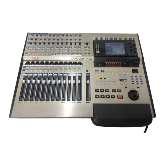
Akai DPS24 Service Manual
Digital personal studio
Hide thumbs
Also See for DPS24:
- Reference manual (252 pages) ,
- Operator's manual (123 pages) ,
- Service manual (29 pages)
Advertisement
Quick Links
All manuals and user guides at all-guides.com
48V
ON
OFF
1
2
3
4
5
6
7
A / B
A
B
A
B
A
B
A
B
A
B
A
B
A
B
LINE
/ MIC
LINE MIC
LINE MIC
LINE MIC
LINE MIC
LINE MIC
LINE MIC
LINE MIC
1
2
3
4
5
6
7
TRIM
0
+60
0
+60
0
+60
0
+60
0
+60
0
+60
0
+60
-15
+45
-15
+45
-15
+45
-15
+45
-15
+45
-15
+45
-15
+45
SIGNAL / CLIP
SIGNAL / CLIP
SIGNAL / CLIP
SIGNAL / CLIP
SIGNAL / CLIP
SIGNAL / CLIP
SIGNAL / CLIP
RECORD
1
1
2
2
3
3
4
4
5
5
6
6
7
/EDIT
SELECT
13
5
14
6
15
7
16
8
17
1
18
2
19
L / R
1 / 2
3 / 4
5 / 6
7 / 8
Q-STRIP
ASSIGN
FUNCTION
Q-CHANNEL
L
R
20Hz
20kHz
-
24dB
+
24dB
20Hz
20kHz
-
24dB
+
24dB
Q
20Hz
20kHz
PAN
LOW
SWEEP
SELECT
ON
SOLO
SOLO
SOLO
SOLO
SOLO
SOLO
SOLO
INPUT 1
2
3
4
5
6
7
TRACK
1 / 13
2 / 14
3 / 15
4 / 16
5 / 17
6 / 18
7 / 19
GROUP 1
GROUP 2
GROUP 3
GROUP 4
GROUP 5
GROUP 6
GROUP 7
DIGITAL PERSONAL STUDIO
8
9
10
11
12
A
B
A
B
A
B
A
B
A
B
LINE MIC
LINE MIC
LINE MIC
LINE MIC
LINE MIC
8
9
10
11
12
MONITOR
LEVEL
0
+60
0
+60
0
+60
0
+60
0
+60
MIN
MAX
-15
+45
-15
+45
-15
+45
-15
+45
-15
+45
SIGNAL / CLIP
SIGNAL / CLIP
SIGNAL / CLIP
SIGNAL / CLIP
SIGNAL / CLIP
!!SOLO!!
7
8
8
9
1
10
2
11
3
12
4
2-TRACK
3
20
4
21
5
22
6
23
7
24
8
MONO
PAN
FX / AUX 1
FX / AUX 2
FX / AUX 3
FX / AUX 4
NEAR
EQ ON
PRE
PRE
PRE
PRE
STUDIO CR
-
24dB
+
24dB
FX / AUX 1
FX / AUX 2
FX / AUX 3
FX / AUX 4
HIGH
EFFECT / AUX SENDS
SELECT
TALK BACK
SOLO
SOLO
SOLO
SOLO
SOLO
8
9
10
11
12
MASTER
8 / 20
9 / 21
10 / 22
11 / 23
12 / 24
GROUP 8
FX RTN 1
FX RTN 2
FX RTN 3
FX RTN 4
L / R
SERVICE MANUAL
CLIP
0
2
4
6
8
10
15
20
25
30
35
40
50
60
L
R
F 1
F 2
F 3
F 4
F 5
F 6
HOURS
MINS
SECS
FRAMES
DISPLAY
SELECT
TB
BARS
BEATS
CLOCKS
LEVEL
EXT
MAIN
SYNC
SCREEN
EDIT
MIXER
AUTOMATE
FX
PROJECT
SETUP
.
-
OFFSET
GRID
DSP
PATCH
V
TRACK
CD
R
MIX SCENE
STORE
RECALL
-
SHIFT
UNDO
REDO
PRE
ROLL
AUTO
CANCEL
ENTER
SET
FADER BANK
INP
TRACKS
TRACKS
GROUP
USER
1-12
1-12
13-24
FX
BANK
INP MON
WHEEL
IN
JOG
TO
FROM
IN OUT
AUTO LOCATE
GO TO
MEMORY
OVER
LOOP
REWIND
FAST FORWARD
STOP
5
5
ABORT
Q 1
Q 2
Q 3
Q 4
Q 5
Q 6
LOCK
RELEASE
CONTRAST
CURSOR
ZOOM
7
8
9
4
5
6
1
2
3
-
+
0
OUT
SHUTTLE
1
Advertisement

Related Manuals for Akai DPS24


Summary of Contents for Akai DPS24
- Page 1 All manuals and user guides at all-guides.com A / B LINE / MIC LINE MIC LINE MIC LINE MIC LINE MIC LINE MIC LINE MIC LINE MIC LINE MIC LINE MIC LINE MIC LINE MIC LINE MIC MONITOR TRIM LEVEL CLIP SIGNAL / CLIP SIGNAL / CLIP...
-
Page 2: Safety Check After Servicing
All manuals and user guides at all-guides.com # SAFETY INSTRUCTIONS # INFORMATIONS 1. Parts identified by the } symbol are critical for safety. SYMBOLS FOR PRIMARY DESTINATION Replace them only with the parts number specified. Unit destinations are indicated with letters as shown below. 2. -
Page 3: Specifications
All manuals and user guides at all-guides.com I. SPECIFICATIONS Specifications Power Supply AC 120V 60Hz (US, Canada), 220-240V 50Hz (Europe) 110W Operating Temperature 10 - 35° C Operating Humidity 10% - 60% (without condensation) Dimensions (mm) 726 (W) x 190 (H) x 579 (D) max. (with LCD tilted down) Weight 17.8kg (without drive) Display... - Page 4 All manuals and user guides at all-guides.com Output Level Stereo Out +4dBu (+22dBu balanced max., 20k ohms load) Main (monitor) +4dBu (+22dBu balanced max., 20k ohms load) Nearfield (monitor) +4dBu (+22dBu balanced max., 20k ohms load) Studio Out +4dBu (+22dBu balanced max., 20k ohms load) Direct Out +4dBu (+22dBu balanced max., 20k ohms load) AUX Sends 1 - 4...
- Page 5 All manuals and user guides at all-guides.com II. DISASSEMBLY In case of trouble, etc., necessitating dismantling, please dismantle in the order shown in the illustrations. Reassemble in the reverse order. 1. Removal of the FRONT PANEL BLOCK ZS-378447 ST BID40X10STL BNI ZS-378447 ST BID40X10STL BNI ZS-331182...
- Page 6 All manuals and user guides at all-guides.com ZS-331182 BT BID30X08STL BNI ZS-331182 BT BID30X08STL BNI 2. Removal of the BOTTOM COVER ZS-331182 BT BID30X08STL BNI ZS-331182 BT BID30X08STL BNI SERVICE MANUAL...
-
Page 7: Principal Parts Location
All manuals and user guides at all-guides.com III. PRINCIPAL PARTS LOCATION PC CONTROL BLK PC OPE-DIST BLK PC FADER BLK PC OPERATION R BLK PC JOG BLK PC OPERATION L BLK PC INPUT A BLK PC LED PAN BLK PC PRE-AMP BLK PC INPUT B BLK PC PAN ENC BLK PC CPU BLK... -
Page 8: Supplementary Information
3-3 With the SHUTTLE knob turned 1/4 to the left, turning the power on will check hard disc content and start up the system in PROJECT initial settings. Normally the DPS24 starts up in the last PROJECT created. This mode is convenient when there is a problem with the last PROJECT data and the system won't start up. - Page 9 Insert in SLOT 1 on the OPTION BOARD. Make sure the power is off before inserting. The JIG PC BOOT will not work in any other slot besides SLOT 1. When the DPS24 power is turned on, the SELF CHECK function will operate to check each CHIP. If a fault is found somewhere, FAILED will appear and operation will stop.
- Page 10 All manuals and user guides at all-guides.com 4. Yous PC should automatically detect the DPS24 and open the New Hardware Wizard. 5. Choose the option in the New Hardware Wizard that allows you to specify the location of the driver files.
- Page 11 All manuals and user guides at all-guides.com Installation of Options IB-24LTC/IB-24ADT 1. Remove the screws for the cover of expansion slot and remove the cover. Save the screws. 2. Slide the Option Board in along the guide groove and press it firmly to ensure secure connection. 3.
- Page 12 Internal Disk Mounting Kit. There are inch-threaded screws and millimeter-threaded screws inside. Be sure to use the appropriate type. 4. Connect the 4-pin Power Cable and 40-pin Disk Drive Cable as illustrated. On the Disk Drive Cable, BLUE connector has to be connected to the CPU board on DPS24. ZS-418538J PAN N06-32UNCXSMM STL CMT 5.
- Page 13 5. Connect the 4-pin Power Cable and 40-pin Disk Drive Cable as illustrated. On the Disk Drive Cable, BLUE connector has to be connect to the CPU board on DPS24. 6. Place the bottom cover back and tighten all screws.
-
Page 14: How To Use This Parts List
All manuals and user guides at all-guides.com V. PARTS LIST ATTENTION 1. When placing an order for parts, be sure to list the Part No., Model No. and the description of each part. Otherwise, the non-delivery of the part or the delivery of a wrong part may result. 2. - Page 15 ED-428998J D SILICON C.1SS355TE-17 T08E BA-L3056A503C PC MOTHER BLK EI-820788X IC GDS1110BD-206MHZ MBGA [unavailable] EI-820802X IC XC2S150-5FG256C MBGA [unavailable] PC(#)OPE R BLK DPS24 CONSISTIS OF FOLLOWING P.C.BOARDS EI-812794J IC XCB56362PV100 TQFP Part No. Description EI-812794J IC XCB56362PV100 TQFP BA-L3056A504A PC OPERATION R BLK...
- Page 16 All manuals and user guides at all-guides.com Ref.No Part No. Description Ref.No Part No. Description BT-810651J TRANS PULSE CIT0705S-35101TFP IC331 EI-810591J IC NJM5532L ET-820772X TR CHIP DTB122JKT146 T08E IC332 EI-810591J IC NJM5532L ET-821162X TR CHIP DTC343TKT146 T08E IC333 EI-821226X IC OPA2134UA FPT12E ET-433976J TR C.DTA114TKA T146T08E IC345...
- Page 17 IC HD74HC595FP FPELT16E TR608 ET-820770X TR 2SD2227S T05 IC726 EI-431115J IC HD74HC595FP FPELT16E TR609 ET-820770X TR 2SD2227S T05 IC727 EI-821440X IC M27C256B45XF1 DPS24 V1.0-OP TR610 ET-820770X TR 2SD2227S T05 IC801 EI-820782X IC BA6286N TR611 ET-820770X TR 2SD2227S T05 IC802 EI-820782X...
- Page 18 All manuals and user guides at all-guides.com Ref.No Part No. Description Ref.No Part No. Description TR712 ET-820771X TR FET CHIP 2SK2103T100 T12E D105 ED-811455J D SILICON H 1SS133T-77 T26 TR713 ET-820771X TR FET CHIP 2SK2103T100 T12E D106 ED-811455J D SILICON H 1SS133T-77 T26 TR714 ET-820771X TR FET CHIP 2SK2103T100 T12E...
- Page 19 All manuals and user guides at all-guides.com Ref.No Part No. Description Ref.No Part No. Description IC301 EI-810591J IC NJM5532L TR354 ET-821232X TR 2SC3329 GR,BL T05 IC351 EI-810591J IC NJM5532L TR401 ET-821232X TR 2SC3329 GR,BL T05 IC401 EI-810591J IC NJM5532L TR402 ET-821232X TR 2SC3329 GR,BL T05 IC451...
- Page 20 All manuals and user guides at all-guides.com Ref.No Part No. Description Ref.No Part No. Description D217 ED-820636X D LED SEL5755C YELLOW D702 ED-812445J IND LE SA04-21IDB D218 ED-820636X D LED SEL5755C YELLOW D703 ED-812445J IND LE SA04-21IDB D221 ED-820665X D LED SEL5955A ORANGE D704 ED-812445J IND LE SA04-21IDB...
- Page 21 All manuals and user guides at all-guides.com Ref.No Part No. Description Ref.No Part No. Description D408 ED-820751X IND LE TOA-L23ZMYMR-91B-LC D307 ED-820779X D LED VRPG3312X RED/GREEN D409 ED-820751X IND LE TOA-L23ZMYMR-91B-LC D308 ED-820779X D LED VRPG3312X RED/GREEN D410 ED-820751X IND LE TOA-L23ZMYMR-91B-LC D309 ED-820779X D LED VRPG3312X RED/GREEN...
- Page 22 All manuals and user guides at all-guides.com Ref.No Part No. Description Ref.No Part No. Description SW349 ES-410552J SW TACT SKHVBE T05 J102 EJ-821223X PHONE J YKB26-5312 S.NUT 6.3 SW350 ES-410552J SW TACT SKHVBE T05 J103 EJ-821223X PHONE J YKB26-5312 S.NUT 6.3 SW351 ES-410552J SW TACT SKHVBE T05...
- Page 23 11. IB-24LTC (OPTION P. C. BOARD) 14. FINAL ASSEMBLY BLK Ref.No Part No. Description Ref.No Part No. Description EJ-429984J SOCKET IC113-0444-004 44P SP-820883X PANEL MAIN (F) DPS24 EI-430810J IC ICS2008AV SP-820884X PANEL MAIN (R) DPS24 EI-812954J IC.TC74HCT139AP SE-820912X ESCUTCHEON REC EI-821190X IC AIC1660CN...
- Page 24 COVER REST EJ-820754X PIN J YKC21-3079 P2P [DIGI I/O] SC-820918X COVER 5 INCH BLANK ZS-322570 ST BID40X08STL NI3 SP-820885X PANEL REAR DPS24 ZS-378447 ST BID40X10STL BNI ZW-413267 N FRANGE 40STL CMT ES-405438J SW SEESAW SDDTA3 TV5 01-1 [POWER SW] EJ-358632J2...
- Page 25 All manuals and user guides at all-guides.com JOG BLK JOG BLK Ref.No Part No. Description SK-820893X KNOB JOG ZS-821450X 6SET30X040SCM PKR WP SK-820894X KNOB SHUTTLE ZS-331182 BT BID30X08STL BNI ZW-820709X SW SHUTTLE SRGPVJ ZW-812440J PW122X160X050STL NI3 ES-820708X SW R.ENCORDER RES20D-50-201-1 BA-L3056A505E PC JOG BLK SERVICE MANUAL...
- Page 26 All manuals and user guides at all-guides.com LCD BLK DPS24 SERVICE MANUAL...
- Page 27 All manuals and user guides at all-guides.com FINAL ASSEMBLY BLK DPS24 A / B LINE / MIC LINE MIC LINE MIC LINE MIC LINE MIC LINE MIC LINE MIC LINE MIC LINE MIC LINE MIC LINE MIC LINE MIC LINE MIC...
- Page 28 All manuals and user guides at all-guides.com FINAL ASSEMBLY BLK DPS24 INPUTS A 1: GROUND INPUTS B 2: HOT 3: COLD 2-TRACK IN AUX IN DIRECT OUT OPTION POWER STEREO OUT MAIN NEARFIELD STUDIO OUT AUX SENDS INSERT INSERT INSERT...
- Page 29 All manuals and user guides at all-guides.com 1-3, Hiranuma 1-Chome, Nishi-Ku, Yokohama, Japan SERVICE SECT. PHONE : +81-45-412-2373 FAX : +81-45-412-2372 SERVICE MANUAL...
Need help?
Do you have a question about the DPS24 and is the answer not in the manual?
Questions and answers