Advertisement
Quick Links
SPECIFICATIONS
Functions: ......................... Effect On/Off
Connectors: ...................... INPUT
Controls: ............................ OUTPUT
Indicators: ......................... LED
Power requirements: ........ 9V DC/50mA
Dimensions: ...................... 134 (W) x 175 (D) x 77 (H) mm
Weight: ............................... 1,350g
Accessories: ..................... Operator's Manual, Battery (9V)
Options: ............................. AC adaptor MP-9
• Specifications are subject to change without notice.
OUTPUT
DC 9V
ON
LOW
+50
D
OUTPUT
M
0
F
C
W
-50
R
F
D
+50
DRIVE
W
0
D
F
-50
R
M
C
LOW
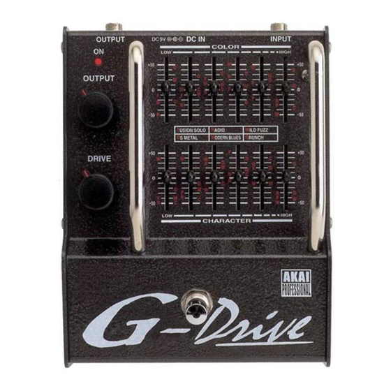
EQUALIZED DISTORTION
MODEL
(Input impedance: 300k ohms or more/Effect On, True Bypass/Effect Off)
OUTPUT (Output impedance: 1k ohms or less/Effect On, True Bypass/Effect Off)
DC IN
(9 Volts)
DRIVE
COLOR x 6
CHARACTER x 6
Footswitch (Effect On/Off)
(Effect ON)
9V Manganese or Alkaline battery, AC adaptor MP-9 (optional)
SERVICE MANUAL
DC IN
INPUT
COLOR
HIGH
+50
W
W
D
C
C
D
R
M
F
D
W
R
M
M
C
M
W
C
D
F
0
M
R
F
F
D
R
R
F
C
W
-50
USION SOLO
R
ADIO
W
ILD FUZZ
S METAL
M
ODERN BLUES
C
RUNCH
+50
F
W
D
C
W
F
M
D
R
C
F
D
M
W
C
0
R
D
C
W
M
M
R
F
D
R
R
C
M
-50
W
F
HIGH
CHARACTER
9
G-DRIVE D2G
1
Advertisement

Related Manuals for Akai G-DRIVE D2G


Summary of Contents for Akai G-DRIVE D2G
- Page 1 ODERN BLUES RUNCH DRIVE HIGH CHARACTER EQUALIZED DISTORTION G-DRIVE D2G MODEL SPECIFICATIONS Functions: ......Effect On/Off Connectors: ...... INPUT (Input impedance: 300k ohms or more/Effect On, True Bypass/Effect Off) OUTPUT (Output impedance: 1k ohms or less/Effect On, True Bypass/Effect Off)
-
Page 2: Safety Check After Servicing
# INFORMATIONS # SAFETY INSTRUCTIONS 1. Parts identified by the } symbol are critical for safety. SYMBOLS FOR PRIMARY DESTINATION Replace them only with the parts number specified. Unit destinations are indicated with letters as shown below. 2. In addition to safety, other parts and assemblies are Symbols Principal Destinations specified for conformance with such regulations as those... - Page 3 BLOCK DIAGRAM...
- Page 4 NOTE : UNLESS OTHERWISE SPECIFIED PC MAIN, PC OPE. ALL RESISTORS IN OHMS 1/6W ALL CAPACITORS IN uF. P=pF SCHEMATIC DIAGRAM 2000/12/08 2000/12/08 ALL ERECTROLYTIC CAPACITORS IN uF/WV SCHEMATIC DIAGRAM L8016001 H.TSUZUKI T.HIRANO File No. AKAI professional M. I. Corp.
-
Page 7: How To Use This Parts List
PARTS LIST ATTENTION 1. When placing an order for parts, be sure to list the Part No., Model No. and the description of each part. Otherwise, the non-delivery of the part or the delivery of a wrong part may result. 2. - Page 8 1. PC BOARD BLK 4. FINAL ASSEMBLY BLK The PC Board Block may contain several PC Boards. They appear Ref.No Part No. Description under its block name without their individual part number. If one of SP-820403X PANEL TOP D2G the PC Board is required, you need to order the whole PC Board block. ZW-384700J1 PROP 2 F.SCREW L=10 The individual PC Board is not available separately.
- Page 9 FINAL ASSEMBLY BLK D2G SERVICE MANUAL...
- Page 10 ABBREVIATIONS FOR THE SERVICE MANUAL ABBREVIATION EXPLANATION ABBREVIATION EXPLANATION AMP (Amp) AMPlifier MINI MINImum Backet Brigade Diode MIXer Binary Code Decimal MODulation / MODulator B.DOWN Brake DOWN M.WHEEL Modulation WHEEL B.UP Back UP OSCillator Chip Enable Programmable Logic Device CHannel Random Access Memory COMP COMParator...
Need help?
Do you have a question about the G-DRIVE D2G and is the answer not in the manual?
Questions and answers