
Related Manuals for Fujitsu Primergy BX900 S2


Summary of Contents for Fujitsu Primergy BX900 S2
-
Page 1: System Unit
Upgrade and Maintenance Manual - English PRIMERGY BX900 S2 System Unit Upgrade and Maintenance Manual December 2012... -
Page 2: Copyright And Trademarks
– The contents of this manual may be revised without prior notice. – Fujitsu assumes no liability for damages to third party copyrights or other rights arising from the use of any information in this manual. – No part of this manual may be reproduced in any form without the prior written permission of Fujitsu. - Page 3 Before reading this manual For your safety This manual contains important information for safely and correctly using this product. Carefully read the manual before using this product. Pay particular attention to the accompanying manual "Safety Notes and Regulations" and ensure these safety notes are understood before using the product.
- Page 4 Please consult the sales staff of Fujitsu if intending to use this product for high safety use. Measures against momentary voltage drop This product may be affected by a momentary voltage drop in the power supply caused by lightning.
- Page 5 Only for the Japanese market: Although described in this manual, some sections do not apply to the Japanese market. These options and routines include: – CSS (Customer Self Service) Upgrade and Maintenance Manual BX900 S2...
- Page 6 Upgrade and Maintenance Manual BX900 S2...
-
Page 7: Table Of Contents
Contents Introduction ......17 Where to find which information? ....18 Notational conventions . - Page 8 Contents Shutting down the system unit ....49 Connecting the system unit to the mains ... 50 Switching on the system unit .
- Page 9 Contents 6.1.1 Power supply redundancy ....86 6.1.2 Cooling requirements ..... . 88 Installing a power supply unit .
- Page 10 Contents 8.2.1 Installing single-width connection blades ... . 112 8.2.1.1 Required tools ......112 8.2.1.2 Preliminary steps .
- Page 11 Contents 8.4.1.3 Replacing SFP+ transceiver modules ... . 136 8.4.2 Connection blade stacking ....137 Management Blades .
- Page 12 Contents 11.2.2 Preliminary steps ......160 11.2.3 Removing the front docking board ....161 11.2.4 Installing the front docking board .
- Page 13 Contents 13.3.3.3 Connection Blade GbE Switch/IBP 36/8+2 (SB11) ..191 13.3.3.4 Connection Blade 10 GbE Switch/IBP 18/8 ..193 13.3.3.5 Connection Blade Ethernet Pass Thru 10Gb 18/18 ..195 13.3.3.6 Connection Blade 8Gb FC Switch 18/8 .
- Page 14 Contents Upgrade and Maintenance Manual BX900 S2...
-
Page 15: Version History
Version history Issue number Reason for update Initial release Description of connection blades DCB SW 10Gb 18/6+6 and FEX B22F 10Gb (Cisco) added Upgrade and Maintenance Manual BX900 S2... - Page 16 Upgrade and Maintenance Manual BX900 S2...
-
Page 17: Introduction
Introduction This Upgrade and Maintenance Manual provides instructions for the following procedures: Upgrading the system unit configuration by adding optional hardware ● components Upgrading the system unit configuration by replacing existing hardware ● components with superior ones. Replacing defective hardware components ●... -
Page 18: Where To Find Which Information
Internet. The overview page showing the online documentation available on the Internet can be found using the URL (for EMEA market): http://manuals.ts.fujitsu.com. The PRIMERGY server documentation can be accessed using the Industry standard servers navigation option. For the Japanese market: Please refer to the following URL for the latest product manuals: http://jp.fujitsu.com/platform/server/primergy/manual/... -
Page 19: Notational Conventions
Introduction Notational conventions The following notational conventions are used in this manual: Text in italics indicates commands or menu items indicates system output fixed font indicates text to be entered by the user semi-bold fixed font "Quotation marks" indicate names of chapters and terms that are being emphasized describes activities that must be performed in the order Ê... - Page 20 Introduction Upgrade and Maintenance Manual BX900 S2...
-
Page 21: Before You Start
Japanese market: http://jp.fujitsu.com/platform/server/primergy/system/ Please contact your local Fujitsu customer service partner for details on how to order expansion kits or spare parts. Use the Fujitsu Illustrated Spares Catalog to identify the required spare part and obtain technical data and order information. -
Page 22: Classification Of Procedures
At the beginning of each procedure, the involved unit type is indicated by one of the symbols introduced in this section. Please ask your local Fujitsu service center for more detailed information. 2.1.1 Customer Replaceable Units (CRU) -
Page 23: Upgrade And Repair Units (Uru)
Before you start Components that are handled as Customer Replaceable Units – Hot-plug PSUs – Hot-plug fan modules – Fan units inside PSUs and fan modules 2.1.2 Upgrade and Repair Units (URU) Upgrade and Repair Units (URU) Upgrade and Repair Units are non hot-plug components that can be ordered separately to be installed as options (Upgrade Units) or are available to the customer through customer self service (Repair Units). -
Page 24: Field Replaceable Units (Fru)
Maintenance procedures involving Field Replaceable Units must be performed exclusively by Fujitsu service personnel or technicians trained by Fujitsu. Please note that unauthorized interference with the system will void the warranty and exempt the manufacturer from all liability. Components that are handled as Field Replaceable Units –... -
Page 25: Tools You Need At Hand
Before you start Step included Explanation Shutdown time depends on hardware and software configuration and may vary significantly. System unit Software tasks necessary before shutdown maintenance are described in section "Starting the maintenance task" on page 63". Rack removal, making the system unit available, removing disassembly the system unit from the rack (if applicable) Transporting the system unit to the service... - Page 26 Before you start Screw driver/ Screw Usage Type Bit insert Phillips PH2 / (+) No. 2 M3 x 16,5 mm hexagonal cross Midplane SW5 / PZ2 MS30165I000 Phillips PH2 / (+) No. 2 M3 x 10 mm hexagonal cross Midplane SW5 / PZ2 FBTU1127010 Phillips...
-
Page 27: Documents You Need At Hand
For the Japanese market please use the following address: http://jp.fujitsu.com/platform/server/primergy/manual/ Document Description "Quick Start Hardware - PRIMERGY BX900 S2 Blade Server" poster Quick installation poster for initial operation, available only in printed form " は じ めにお読み く だ さ い - PRIMERGY BX900 S2 Blade Server"... - Page 28 Spare parts identification and information system (EMEA market only), available for online use or download (Windows OS) at Illustrated Spares catalog http://manuals.ts.fujitsu.com/illustrated_spares or from the CSS component view of the ServerView Operations Manager available from the ServerView Suite DVD 2...
-
Page 29: Important Information
Important information CAUTION! Before installing and starting up a device, please observe the safety instructions listed in the following section. This will help you to avoid making serious errors that could impair your health, damage the device and endanger the data base. Keep this operating manual and the other documentation (such as the technical manual, documentation DVD) close to the device. - Page 30 Important information Before starting up During installation and before operating the device, observe the instructions ● on environmental conditions for your device. If the device is brought in from a cold environment, condensation may form ● both inside and on the outside of the device. Wait until the device has acclimatized to room temperature and is absolutely dry before starting it up.
- Page 31 Important information Always connect the server and the attached peripherals to the same power ● circuit. Otherwise you run the risk of losing data if, for example, the server is still running but a peripheral device (e.g. memory subsystem) fails during a power outage.
- Page 32 Important information Only set screen resolutions and refresh rates that are specified in the ● operating manual for the monitor. Otherwise, you may damage your monitor. If you are in any doubt, contact your sales outlet or customer service center. Before installing/removing internal options to/from the server, turn off the ●...
- Page 33 Important information Batteries Incorrect replacement of batteries may lead to a risk of explosion. The ● batteries may only be replaced with identical batteries or with a type recommended by the manufacturer. Do not throw batteries into the trash can. ●...
- Page 34 Important information High humidity and airborne dust levels are to be avoided. Electric ● shocks and/or server failures may be caused by liquids such as water, or metallic items, such as paper clips, entering a drive. Shocks and vibrations are also to be avoided. ●...
- Page 35 Important information Do not store CDs/DVDs/BDs at high temperatures. Areas exposed to ● prolonged direct sunlight or near heating appliances are to be avoided. You can prevent damage from the optical drive and the CDs/DVDs/BDs, as well as premature wear of the disks, by observing the following suggestions: –...
- Page 36 Only unpack the system unit at the place where you want to set it up. Ask someone for help with carrying the system unit. Because the ● PRIMERGY BX900 S2 system unit is large and heavy, at least three people are needed. Before lifting the system unit, remove all server blades, storage blades, ●...
- Page 37 Important information Notes on installation into the rack For safety reasons, at least three people are required to install the ● system unit in the rack because of its weight and size. Refer to section 5.2 "Installing/removing the system unit" in the "PRIMERGY BX900 S2 Blade Server System Operating Manual".
-
Page 38: Ce Conformity
Important information CE conformity The system complies with the requirements of the EC directives 2004/108/EC regarding "Electromagnetic Compatibility" and 2006/95/EC "Low Voltage Directive". This is indicated by the CE marking (CE = Communauté Européenne). Upgrade and Maintenance Manual BX900 S2... -
Page 39: Fcc Class A Compliance Statement
Consult the dealer or an experienced radio/TV technician for help. ● Fujitsu is not responsible for any radio or television interference caused by unauthorized modifications of this equipment or the substitution or attachment of connecting cables and equipment other than those specified by Fujitsu. The correction of interferences caused by such unauthorized modification, substitution or attachment will be the responsibility of the user. -
Page 40: Environmental Protection
Important information Environmental protection Environmentally-friendly product design and development This product has been designed in accordance with the Fujitsu standard for "environmentally friendly product design and development". This means that key factors such as durability, selection and labeling of materials, emissions, packaging, ease of dismantling and recycling have been taken into account. - Page 41 Details regarding the return and recycling of devices and consumables within Europe can also be found in the "Returning used devices" manual, via your local Fujitsu branch or from our recycling center in Paderborn: Fujitsu Technology Solutions Recycling Center D-33106 Paderborn Tel.
- Page 42 Important information Upgrade and Maintenance Manual BX900 S2...
-
Page 43: Basic Hardware Procedures
– Operation – Maintenance Please contact your local Fujitsu customer service partner for details on the service concept and on how to order expansion kits or spare parts. Use the Fujitsu Illustrated Spares Catalog to identify the required spare part and obtain technical data and order information. -
Page 44: Accessing The Management Blade Web Interface
Basic hardware procedures 4.1.1 Accessing the management blade web interface For checking the current system status and administration of the system unit, connect a field service terminal (FST, e.g. notebook) to the management blade and login to the management blade web interface. Figure 2: Connectors on the management blade Ê... -
Page 45: Locating The Defective System Unit
Basic hardware procedures Ê Connect the FST to the serial port of the management blade (3) and open a terminal session, see the "PRIMERGY BX900 Blade Server Systems ServerView Management Blade S1 User Interface Description". Ê Open the Management Agent – Management Agent Information menu to view the Management Agent Administrative URL. - Page 46 Basic hardware procedures Global Error and CSS indicate, if the defective component is a customer replaceable unit or if maintenance personnel needs to be dispatched to replace the part. The indicators also light up in standby mode and after a system unit restart due to a power failure.
-
Page 47: Global Error Indicator
Basic hardware procedures 4.1.3.1 Global Error indicator Ê Check the Global Error indicator on the front panel or management blade of the system unit (see section "Connectors and indicators" on page 179). Indicator Status Description no critical event (non CSS component) prefailure detected (non CSS component), orange on requires (precautionary) service... -
Page 48: Locating The Defective Component
19-inch rack, please refer to the "19-inch Rack for PRIMERGY and RM systems" assembly guide, available online at http://manuals.ts.fujitsu.com or from the ServerView Suite DVD 2 supplied with your PRIMERGY server. The PRIMECENTER rack is equipped with a split front door. The left-hand door contains an interlocking system that can be locked and opened with a key. -
Page 49: Shutting Down The System Unit
Ê Terminate all applications of the server blades. Ê Shut down the system unit by pressing the On/Off button for 2 seconds or via the management blade web interface, see the "PRIMERGY BX900 S2 Blade Server System Unit Operating Manual" for detailed information. -
Page 50: Connecting The System Unit To The Mains
Basic hardware procedures Connecting the system unit to the mains The system unit has six bays for hot-swap power supply units (PSUs). In the base configuration, it is fitted with three PSUs. CAUTION! Read the information on determining how many PSUs are required ●... - Page 51 Basic hardware procedures Securing power cords Figure 4: Securing power cords Ê Route the cable through the loop of the cable tie (1). Ê Pull the cable tie tight to secure the power cable. Upgrade and Maintenance Manual BX900 S2...
-
Page 52: Switching On The System Unit
Basic hardware procedures Switching on the system unit CAUTION! Follow the safety instructions in chapter "Important information" on page Ê Connect all peripheral cables to the connection blades of the system unit. Ê Connect and secure the power cords as described in section "Connecting the system unit to the mains"... - Page 53 Basic hardware procedures Thus 3+3 redundancy is supported; the system continues to run if one source fails, provided the remaining 3 power supplies are sufficient to deliver the required power. With 4 PSUs, you must connect units 2 and 3 to the first source (phase) and units 5 and 6 to the second.
-
Page 54: Removing / Installing Server Blades And Storage Blades
Basic hardware procedures Removing / installing server blades and storage blades CAUTION! Make sure you observe the safety notes and the information on ● handling electrostatic-sensitive devices in the section "Modules with Electrostatic-Sensitive Devices" on page Beware of the energy hazard at the midplane contacts. A short circuit ●... -
Page 55: Installing A Single Height / Single Width Blade
Basic hardware procedures 4.6.1 Installing a single height / single width blade The following describes how to install a BX92x Sx server blade. Storage blades are installed in the same way. Figure 6: Installing the BX92x Sx server blade Ê Undo the locking mechanism of the release lever (1). Ê... - Page 56 Basic hardware procedures Figure 7: Locking the BX92x Sx server blade Ê Push the release lever up until it clicks into place under the locking lever (1). Removal is carried out in reverse order. Upgrade and Maintenance Manual BX900 S2...
-
Page 57: Installing A Single Height / Double Width Blade
Basic hardware procedures 4.6.2 Installing a single height / double width Blade The following describes how to install a BX960 S1 server blade. This server blade occupies 2 bays one upon the other in the BX900 S2 system unit. Figure 8: Installing a BX960 S1 server blade Ê... - Page 58 Basic hardware procedures Figure 9: Locking the BX960 S1 server blade Ê Push the release lever up until it clicks into place under the locking lever (1). Removal is carried out in reverse order. Upgrade and Maintenance Manual BX900 S2...
-
Page 59: Installing A Dummy Server Blade Module
Basic hardware procedures 4.6.3 Installing a dummy server blade module Any unused server blade slots must be fitted with dummy modules to comply with EMC regulations for the system and to ensure sufficient cooling of the components. Figure 10: Dummy server blade module The handle (1) is movable and acts as a release lever. -
Page 60: Concluding Software Tasks
Basic hardware procedures Figure 11: Installing a dummy server blade module Ê Push the dummy server blade into the empty slot until it clicks into place. Concluding software tasks Ê Perform the following software tasks to put the system unit back in operation: –... - Page 61 If applicable, turn the door knob clockwise by 180 degrees. For further information, refer to the "PRIMECENTER Rack System" assembly guide available online at or from the http://manuals.ts.fujitsu.com ServerView Suite DVD 2 supplied with your PRIMERGY server. Upgrade and Maintenance Manual BX900 S2...
- Page 62 Basic hardware procedures Upgrade and Maintenance Manual BX900 S2...
-
Page 63: Basic Software Procedures
Basic software procedures Starting the maintenance task 5.1.1 Switching on the ID indicator When working in a datacenter environment, switch on the ID indicator on the front and rear of the system unit for easy identification. For further information, refer to section "Locating the defective system unit"... -
Page 64: Saving / Restoring Management Blade Settings
Basic software procedures 5.1.2 Saving / Restoring management blade settings Non-default management blade settings are automatically stored from the management blade NVRAM to the Chassis ID EPROM which is located in the front docking board. To avoid the loss of management blade settings when replacing the front docking board, you must create a backup copy of the management blade settings. - Page 65 Basic software procedures Ê Enter the Backup/Restoration tab. Ê In the Restore Configuration box select the backup media. – Select USB, if the backup copy is stored on a USB memory stick plugged in to the management blade. – Select Local File, if the backup copy is saved in the file system of the field service terminal.
-
Page 66: Completing The Maintenance Task
– The only one management blade of a system unit has been replaced. The management blade firmware must be updated to the same or a later firmware version as of the old management blade. The latest firmware versions are available from the Fujitsu support internet pages at: http://ts.fujitsu.com/support/ (EMEA market) http://jp.fujitsu.com/platform/server/primergy/downloads/... -
Page 67: Updating The Management Blade Firmware Via Management Blade Web Interface
Basic software procedures 5.2.1.2 Updating the management blade firmware via management blade web interface TFTP update procedure Ê Enter the management blade web interface, see section "Accessing the management blade web interface" on page Ê Open the Information / Operation – Operation – Firmware Update menu. Ê... -
Page 68: Updating The Management Blade Firmware Via Recovery Flash
Basic software procedures 5.2.1.3 Updating the management blade firmware via recovery flash Ê Open the management blade, as described in section "Opening the management blade" on page 149. Ê Enter recovery mode using the DIP switch, see section "Management Blade Settings"... - Page 69 Basic software procedures Ê Enter 4 to set the gateway address of subnet mask. Ê Enter 5 to set the TFTP file name. Ê Enter 0 to leave the Network Paramenters menu. Ê Connect the FST to the service LAN connector of the management blade, see pos.
-
Page 70: Verifying The Management Blade Time Settings
Basic software procedures 5.2.2 Verifying the management blade time settings After a management blade has been replaced, you must check the system time settings. System unit with one management blade installed Ê After replacing the management blade, ask the system administrator whether the RTC or UTC time standard is to be used as system time. -
Page 71: Viewing And Clearing The System Event Log (Sel)
Basic software procedures 5.2.3 Viewing and clearing the System Event Log (SEL) 5.2.3.1 Viewing the SEL You can view the System Event Log (SEL) of the management blades and server blades using the management blade web interface and ServerView Operations Manager frontend: Viewing the SEL using the management blade web interface Ê... -
Page 72: Clearing The Sel
Basic software procedures 5.2.3.2 Clearing the SEL You can clear the System Event Log (SEL) using the management blade web interface: Ê Enter the management blade web interface, see section "Accessing the management blade web interface" on page Ê Select the Components – System – Management Blades – Management Blade-x menu or the Components –... -
Page 73: Checking Management Master/Slave Behavior
Basic software procedures 5.2.4 Checking management master/slave behavior This task applies, if two management blades are installed in the system unit. When a management blade is replaced, the new one takes on the slave role. To verify whether the new management blade is OK, you must switch/change the master/slave assignment and verify the settings of the master. -
Page 74: Updating The Connection Blade Firmware
Basic software procedures 5.2.5 Updating the connection blade firmware When replacing a connection blade make sure that the firmware version of the new connection blade matches the firmware version of the old one. Looking up the connection blade firmware version Ê... -
Page 75: Configuring Connection Blade Settings
Basic software procedures 5.2.6 Configuring connection blade settings Configuring out-of-band settings of a connection blade Ê Login to the management blade web interface, see section "Accessing the management blade web interface" on page Ê Open the Components – System – Connection Blades – Connection Blade-x menu for the desired connection blade. -
Page 76: Saving Connection Blade Settings
Basic software procedures 5.2.7 Saving connection blade settings After replacing and configuring a connection blade you must create a backup copy of the connection blade settings. Saving out-of-band connection blade settings Perform the following steps to create a backup copy of the out-of-band configuration data of a connection blade. - Page 77 Basic software procedures Ê In the Backup/Restoration Configuration box of the Connection Blade Configuration click the Apply button. The file manager obtains access to a web site of the connection blade where the current configuration of the connection blade can be saved or restored. For detailed information, please refer to the relevant connection blade manual.
-
Page 78: Restoring Connection Blade Settings
Basic software procedures 5.2.8 Restoring connection blade settings Restoring out-of-band connection blade settings Perform the following steps to restore a backup copy of out-of-band connection blade settings. Ê If not done yet, login to the management blade web interface, see section "Accessing the management blade web interface"... - Page 79 Basic software procedures The file manager obtains access to a web site of the connection blade where the current configuration of the connection blade can be saved or restored. For detailed information, please refer to the relevant connection blade manual. Upgrade and Maintenance Manual BX900 S2...
-
Page 80: Verifying Power Consumption
Basic software procedures 5.2.9 Verifying power consumption This task applies only, if a PSU must be replaced, which has not failed completely. Ê Login to the management blade web interface, see section "Accessing the management blade web interface" on page Ê... -
Page 81: Configuring Power Supply Redundancy
Basic software procedures 5.2.10 Configuring power supply redundancy Ê Login to the management blade web interface, see section "Accessing the management blade web interface" on page Ê Open the Information/Operation – Operation – Power Management menu, select the Configuration tab and scroll to the Power Consumption Options box. Ê... -
Page 82: Using The Chassis Id Prom Tool
After replacing the front docking board, system information has to be entered using the ChassisId_Prom Tool. The tool and further instructions are available to maintenance personnel from the Fujitsu Technology Solutions Extranet: http://partners.ts.fujitsu.com/com/service/intelservers/tools For the Japanese market, follow the instructions provided separately. -
Page 83: Switching Off The Id Indicator
Basic software procedures 5.2.12 Switching off the ID indicator Press the ID button on the Local Service Display or on the management blade or use the management blade web interface to switch off the ID indicator after the maintenance task has been concluded successfully. For further information, refer to section "Locating the defective system unit"... - Page 84 Basic software procedures Upgrade and Maintenance Manual BX900 S2...
-
Page 85: Power Supply
Power supply This chapter provides information on how to replace the power supply unit (PSU). CAUTION! A combination of standard PSUs and high efficiency PSUs in one ● BX900 S2 system unit is not allowed. The system unit supports a mains voltage in the range of 100 VAC to ●... -
Page 86: Basic Information
The BX900 S2 system unit has 6 bays for hot-plug PSUs (PSU 1-6). There are two types of PSUs available, standard PSU and High Efficiency PSU (hereinafter referred to as HE PSU), see the "PRIMERGY BX900 S2 Blade Server System Unit Operating Manual". - Page 87 The numbers of installed server blades in the following table are only approximate values. For further information regarding Power Consumption and Power Efficiency please refer to http://ts.fujitsu.com/products/standard_servers/e_efficient.html (for the EMEA market) http://jp.fujitsu.com/platform/server/primergy/technical/ (for the Japanese market)
-
Page 88: Cooling Requirements
Power supply CAUTION! If a PSU fails in a non-redundant configuration of PSUs, and the remaining PSUs do not provide sufficient power, the system unit is shut down immediately. Make sure that the individual PSUs are connected to different phases. This ensures additional phase redundancy for high availability configurations. - Page 89 Power supply Configuration with three power supply units (minimum configuration) Zone 5 Zone 3 Zone 1 Zone 1 Zone 3 Zone 5 PSU 1 PSU 2 PSU 3 17 5 PSU 4 PSU 5 PSU 6 10 11 12 18 13 14 15 16 Zone 6 Zone 4 Zone 2...
- Page 90 Power supply Configuration with four power supply units or with three power supply units and one fan module. Zones 1, 2 and 3 must always be fitted with a PSU. Zone 4 can alternatively be fitted with one PSU or one fan module. Zone 5 Zone 3 Zone 1...
- Page 91 Power supply Configuration with five power supply units or with four power supply units and one fan module or with three power supply units and two fan modules. Zones 1, 2 and 3 must always be fitted with a PSU. Zones 4 and 5 can be fitted with either PSUs or fan modules.
- Page 92 Power supply Configuration with six power supply units or five power supply units and one fan module. Zones 1, 2 and 3 must always be fitted with a PSU. Zones 4, 5 and 6 can be fitted with either PSUs or fan modules. Zone 5 Zone 3 Zone 1...
-
Page 93: Installing A Power Supply Unit
Power supply Installing a power supply unit Customer Replaceable Units (CRU) average hardware task duration: 5 minutes average software task duration: 5 minutes 6.2.1 Required tools Preliminary and concluding steps: tool-less ● Replacing the fan module: tool-less ● 6.2.2 Preliminary steps Before installing a power supply unit (PSU), perform the following steps: Ê... -
Page 94: Installing A Power Supply Unit
Power supply 6.2.3 Installing a power supply unit Figure 14: Open release lever Ê Open the release lever (1). Ê Push the PSU as far as possible into the empty bay (2). Ê Swivel the release lever down until it clicks into place under the locking lever. 6.2.4 Concluding steps Perform the following procedures to complete the task:... -
Page 95: Replacing A Power Supply Unit
Power supply Replacing a power supply unit Customer Replaceable Units (CRU) average hardware task duration: 5 minutes average software task duration: 10 minutes 6.3.1 Required tools Preliminary and concluding steps: tool-less ● Replacing the fan module: tool-less ● 6.3.2 Preliminary steps Before replacing the power supply unit (PSU), perform the following steps: Ê... -
Page 96: Removing The Power Supply Unit
Power supply 6.3.3 Removing the power supply unit Figure 15: Open release lever Ê Unlock the locking lever (1) and open the release lever (2). Figure 16: Removing the PSU Ê Pull the PSU out of its bay. Upgrade and Maintenance Manual BX900 S2... -
Page 97: Concluding Steps
Power supply 6.3.4 Concluding steps Perform the following procedures to complete the task: Ê Install the new PSU as described in section "Installing a power supply unit" on page Ê Connect the AC power cord to the PSU and secure it with a cable tie as described in section "Connecting the system unit to the mains"... - Page 98 Power supply Upgrade and Maintenance Manual BX900 S2...
-
Page 99: Fan Module And Fan Unit
Fan module and fan unit This chapter provides information on how to replace a fan module and a fan unit. Safety notes CAUTION! Please refer to chapter "Important information" on page Whether and how many fan modules need to be installed depends on the number of server blades installed and on the redundant power supply requirements, see section "Cooling requirements"... -
Page 100: Removing The Fan Module
Fan module and fan unit Ê Locate the desired system unit as described in section "Determining the error class" on page Ê Locate the defective fan module as described in section "Locating the defective component" on page 7.1.3 Removing the fan module Fan modules are removed in the same way as PSUs, see "Removing the power supply unit"... -
Page 101: Replacing A Fan Unit
Fan module and fan unit Replacing a fan unit PSUs and fan modules contain a fan unit on each of their front and rear sides. The mounting positions of the fan units are the same for PSUs and fan modules. Figure 17: Fan units in a PSU CAUTION! Do not install fan units of high efficiency PSUs in standard PSUs or in fan... -
Page 102: Preliminary Steps
Fan module and fan unit 7.2.2 Preliminary steps Before replacing the fan module, perform the following steps: Ê If applicable, open the rack door as described in section "Opening the rack door" on page Ê Locate the desired system unit as described in section "Determining the error class"... -
Page 103: Installing The Fan Unit
Fan module and fan unit 7.2.4 Installing the fan unit Figure 19: Installing a fan unit Ê Insert the fan unit such that the airflow is directed out of the back of the system unit. The printed airflow arrow must point to the back of the system unit. - Page 104 Fan module and fan unit Upgrade and Maintenance Manual BX900 S2...
-
Page 105: Connection Blades
Basic information The PRIMERGY BX900 S2 system unit has 8 slots on the back for connection blades for connecting the server blades to LAN and SAN networks. How to configure and operate the connection blades is explained in separate manuals. -
Page 106: Connection Blade Fitting Rules
Connection blades 8.1.1 Connection blade fitting rules Fabric 1 Fabric 2 Fabric 3 Fabric 4 Figure 20: Connection blade slots Each pair of adjacent connection blade slots forms a so-called fabric. The following table shows how you can fill the fabrics and which network components of the server blades they are connected to: System unit Server blade... - Page 107 Connection blades System unit Server blade Connection blade slots CB5: CB6: 1Gb Ethernet or 1Gb Ethernet or 10 Gb Ethernet or 10 Gb Ethernet or DCB SW 10Gb or DCB SW 10Gb or FEX B22F 10Gb FEX B22F 10Gb Fabric 3 (Cisco) or (Cisco) or Mezzanine card 2...
- Page 108 Connection blades In this case, only one of two channels of the Infiniband mezzanine card is used. If a 1 Gb Ethernet mezzanine card is installed in slot 2 of a server blade, at ● least one 1 Gb Ethernet connection blade must be installed in fabric 3 or in fabric 4 of the system unit.
-
Page 109: Port Assignment
Connection blades 8.1.2 Port assignment For the on-board LAN controller, the Ethernet and Fibre Channel mezzanine cards of the server blades applies the following general rule: The A-channels (Ethernet: ports 1 and 3, FC: port 0) are connected to the connection blade slots on the left-hand side (CB1, CB3, CB5 and CB7). -
Page 110: Port Assignment Of Switch Connection Blades
Connection blades 8.1.2.1 Port assignment of switch connection blades With the mezzanine cards, the assignment of the ports to the connection blade slots can be defined via the management blade. The following table shows the different options. mezzanine card Mezzanine card slot (M) Connection blade slot (CB) Port (P) Port (P) -
Page 111: Port Assignment Of Connection Blade 8Gb Fc Pass Thru 18/18
Connection blades 8.1.2.2 Port assignment of connection blade 8Gb FC pass thru 18/18 Each of the 18 server blades of a BX900 S2 system unit can be equipped with 2 FC mezzanine cards each with 2 ports (0, 1). Each of the server blade FC ports is connected to a dedicated port of an FC pass thru connection blade in a defined connection blade slot. -
Page 112: Single-Width Connection Blades
Connection blades The configuration of the connection blade is controlled by the management blade. Each port group can be configured to a certain link protocol. The management blade web interface allows the user to modify the port group link speed configuration. Single-width connection blades 8.2.1 Installing single-width connection blades... -
Page 113: Removing Connection Blade Dummy Module
Connection blades 8.2.1.3 Removing connection blade dummy module Figure 21: Removing a dummy connection blade module Ê Press the handles of the dummy module inward and pull it out of the slot. CAUTION! Keep the dummy modules for future use. Always replace connection blade dummy modules into unused connection blade slots to comply with applicable EMC regulations and satisfy cooling requirements. - Page 114 Connection blades Figure 22: Installing a connection blade Ê Open the release lever (1) of the connection blade and push it carefully into the empty slot. Figure 23: Locking the connection blade Ê Push the connection blade into the slot as far as it will go. Ê...
-
Page 115: Concluding Steps
Connection blades 8.2.1.5 Concluding steps Perform the following procedures to complete the task: Ê If applicable, install the SFP transceiver modules as described in section "Installing SFP+ transceiver modules" on page 127 Ê Connect the external cables to the connection blade. Ê... -
Page 116: Removing A Single-Width Connection Blade
Connection blades Ê Save the connection blade settings as described in section "Saving connection blade settings" on page Ê If applicable, open the rack door as described in section "Opening the rack door" on page Ê Locate the desired system unit as described in section "Determining the error class"... -
Page 117: Installing A Connection Blade Dummy Module
Connection blades 8.2.2.4 Installing a connection blade dummy module Figure 25: Installing a dummy connection blade module Ê Push the connection blade dummy module into the slot until the handles click into place. 8.2.2.5 Concluding steps Perform the following procedures to complete the task: Ê... -
Page 118: Preliminary Steps
Connection blades 8.2.3.2 Preliminary steps Before replacing a single-width connection blade, perform the following steps: Ê If possible, save the connection blade settings as described in section "Saving connection blade settings" on page Ê If applicable, open the rack door as described in section "Opening the rack door"... -
Page 119: Double-Width Connection Blades
Connection blades Ê If applicable, close the rack door as described in section "Closing the rack door" on page Ê Make sure, that the new connection blade has the same firmware version as the old one as described in section "Updating the connection blade firmware"... -
Page 120: Removing Connection Blade Dummy Modules
Connection blades Ê Locate the mounting bay for the new connection blade using the information in section "Connection blade fitting rules" on page 106. 8.3.1.3 Removing connection blade dummy modules Ê Remove the connection blade dummy modules from the side by side slots of a fabric as described in section "Removing connection blade dummy module"... - Page 121 Connection blades Because of the double width of these connection blades, you must remove the separating clip between the two slots of a fabric before you install the connection blade. Ê Remove the separating clip by pressing the little black lever (see blow-up in figure 26) to the left and pulling out the separating clip.
-
Page 122: Concluding Steps
Connection blades 8.3.1.5 Concluding steps Perform the following procedures to complete the task: Ê Install the QSFP transceiver modules as described in section "Installing SFP+ transceiver modules" on page 127 Ê Connect the external cables to the connection blade. Ê If applicable, close the rack door as described in section "Closing the rack door"... -
Page 123: Removing Double-Width Connection Blades
Connection blades 8.3.2 Removing double-width connection blades Upgrade and Repair Units (URU) average hardware task duration: 5 minutes average software task duration: 10 minutes 8.3.2.1 Required tools Preliminary and concluding steps: tool-less ● Removing connection blades: tool-less ● 8.3.2.2 Preliminary steps Before removing a double-width connection blade, perform the following steps: Ê... -
Page 124: Removing A Double-Width Connection Blade
Connection blades 8.3.2.3 Removing a double-width connection blade Figure 29: Removing a double-width connection blade Ê Unlock the locking lever (1) and open the release lever (2). Ê Carefully remove the connection blade from its slot. 8.3.2.4 Installing connection blade dummy modules Figure 30: Installing the separating clip between the connection blade slots Ê... -
Page 125: Concluding Steps
Connection blades 8.3.2.5 Concluding steps Perform the following procedures to complete the task: Ê If applicable, close the rack door as described in section "Closing the rack door" on page 8.3.3 Replacing double-width connection blades Upgrade and Repair Units (URU) average hardware task duration: 5 minutes average software task duration: 10 minutes 8.3.3.1... -
Page 126: Removing The Connection Blade
Connection blades 8.3.3.3 Removing the connection blade Ê Remove the defective connection blade as described in section "Removing a double-width connection blade" on page 124. 8.3.3.4 Installing a double-width connection blade Ê Install the new connection blade as described in section "Installing a double- width connection blade (Infiniband)"... -
Page 127: Additional Tasks
Connection blades Additional tasks This section provides additional connection blade related information on how to install SFP+ transceiver modules. For further instructions regarding connection blade settings, please refer to the accompanying documentation. 8.4.1 Handling SFP+ transceiver modules 8.4.1.1 Installing SFP+ transceiver modules Customer Replaceable Units (CRU) Average task duration: 5 minutes Required tools... - Page 128 Connection blades Preparing the SFP+ transceiver module Figure 31: Removing the protective optical port plug Upgrade and Maintenance Manual BX900 S2...
- Page 129 Connection blades Ê Remove the SFP+ transceiver module from its protective packaging. Ê Remove the optical port plug from the new / additional SFP+ transceiver module. CAUTION! – Always keep the protective port plugs attached to the transceiver optical bores and fiber-optic cable connectors until you are ready to make a connection.
- Page 130 Connection blades Inserting the SFP+ transceiver module Figure 33: Inserting the SFP+ transceiver module Ê Insert and slide the SFP+ transceiver module into the socket connector as far as it will go. If only one slot is equipped with a SFP+ transceiver module, use the primary left connector as shown.
- Page 131 Connection blades Figure 34: Latching the locking bail Ê Carefully fold up and latch the locking bail. Figure 35: Attaching the protective optical port plug Upgrade and Maintenance Manual BX900 S2...
- Page 132 Connection blades Ê If the SFP+ transceiver module is not immediately connected to an LC connector, attach the protective optical port plug to the transceiver optical bores. Upgrade and Maintenance Manual BX900 S2...
-
Page 133: Removing An Sfp+ Transceiver Module
Connection blades 8.4.1.2 Removing an SFP+ transceiver module Customer Replaceable Units (CRU) Average task duration: 5 minutes Required tools Preliminary and concluding steps: tool-less ● Removing SFP+ transceiver modules: tool-less ● Figure 36: Removing the protective optical port plug Ê If present, remove the protective optical port plug from the SFP+ transceiver module. - Page 134 Connection blades Figure 37: Unlatching the locking bail Ê Carefully unlatch and fold down the locking bail on the SFP+ transceiver module to eject the transceiver from the socket connector. Figure 38: Removing the SFP+ transceiver Upgrade and Maintenance Manual BX900 S2...
- Page 135 Connection blades Ê Pull the SFP+ transceiver module out of its socket connector. Ê Reattach the protective optical port plug to the transceiver optical bores. Place the removed SFP+ transceiver module in an antistatic bag or other protective environment. Upgrade and Maintenance Manual BX900 S2...
-
Page 136: Replacing Sfp+ Transceiver Modules
Connection blades 8.4.1.3 Replacing SFP+ transceiver modules Customer Replaceable Units (CRU) Average task duration: 5 minutes Required tools Preliminary and concluding steps: tool-less ● Removing SFP+ transceiver modules: tool-less ● Removing SFP+ transceiver modules Ê Remove the defective SFP+ transceiver module(s) as described in section "Removing an SFP+ transceiver module"... -
Page 137: Connection Blade Stacking
Connection blades 8.4.2 Connection blade stacking Up to 8 Connection Blades GbE Switch/IBP 36/8+2 (SB11) can be operated together to form a so-called stack. One of the connection blades takes on the role of the master. This connection blade is used to administer all modules of the stack. - Page 138 Connection blades Cable connections within a system unit Fabric 1 Fabric 2 Fabric 3 Fabric 4 Figure 40: Stack with 2 connection blades within a fabric Fabric 1 Fabric 2 Fabric 3 Fabric 4 Figure 41: Stack with 4 connection blades Fabric 1 Fabric 2 Fabric 3...
- Page 139 Connection blades Cable connections across several system units Fabric 1 Fabric 2 Fabric 3 Fabric 4 Fabric 1 Fabric 2 Fabric 3 Fabric 4 Fabric 1 Fabric 2 Fabric 3 Fabric 4 Fabric 1 Fabric 2 Fabric 3 Fabric 4 Figure 44: Stack with 8 connection blades in 4 system units in a rack (variant 1) Upgrade and Maintenance Manual BX900 S2...
- Page 140 Connection blades Fabric 1 Fabric 2 Fabric 3 Fabric 4 Fabric 1 Fabric 2 Fabric 3 Fabric 4 Fabric 1 Fabric 2 Fabric 3 Fabric 4 Fabric 1 Fabric 2 Fabric 3 Fabric 4 Figure 45: Stack with 8 connection blades in 4 system units in a rack (variant 2) Upgrade and Maintenance Manual BX900 S2...
- Page 141 Connection blades Supported combinations for connection blade stacks The following table shows the possible combinations of connection blade stacks. Columns a - f contain permissible numbers and distributions of the connection blades for the different combinations of BX900 S2 system units and racks.
-
Page 142: Further Information
Connection blades Fitting variants of connection blades System Rack (R) unit (Z) 4 racks, 4 system units Further information For more detailed information and additional possible configurations, see the manuals "PRIMERGY BX900 Blade Server Systems – Ethernet Connection Blade Module IBP Version – User’s Guide", "PRIMERGY BX900 Blade Server Systems –... -
Page 143: Management Blades
Management Blades Basic information The PRIMERGY BX900 S2 system unit has slots for two management blades for complete remote administration of the system, MMB 1 and MMB 2 in figure "PRIMERGY BX900 S2 system unit rear" on page 176. The basic configuration of the BX900 S2 system unit contains one management blade. -
Page 144: Installing A Second Management Blade
Management Blades Installing a second management blade Field Replaceable Units (FRU) average hardware task duration: 5 minutes average software task duration: 10 minutes 9.2.1 Required tools Preliminary and concluding steps: tool-less ● Installing connection blades: tool-less ● 9.2.2 Preliminary steps Before installing a management blade, perform the following steps: Ê... -
Page 145: Installing The Management Blade
Management Blades A management blade dummy module is removed in the same way as a connection blade dummy module as described in section "Removing connection blade dummy module" on page 113. CAUTION! Keep the dummy module for future use. Always replace the management blade dummy module into an unused management blade slot to comply with applicable EMC regulations and satisfy cooling requirements. -
Page 146: Replacing A Management Blade
Management Blades Replacing a management blade Field Replaceable Units (FRU) average hardware task duration: 5 minutes average software task duration: 10 minutes 9.3.1 Required tools Preliminary and concluding steps: tool-less ● Installing connection blades: tool-less ● 9.3.2 Preliminary steps Before replacing a management blade, perform the following steps: Ê... -
Page 147: Removing The Defective Management Blade
Management Blades Ê Take a note of the firmware version of the master management blade as described in section "Looking up the management blade firmware version" on page 9.3.3 Removing the defective management blade Ê Remove the defective management blade. A management blade is removed in the same way as a single-width connection blade as described in section "Removing a single-width... -
Page 148: Replacing The Management Blade Battery
Management Blades Ê Verify the time settings of the new management blade as described in section "Verifying the management blade time settings" on page Ê Disconnect the field service terminal from the management blade. Ê If applicable, close the rack door as described in section "Closing the rack door"... - Page 149 Management Blades A management blade is removed in the same way as a single-width connection blade as described in section "Removing a single-width connection blade" on page 116. Opening the management blade Figure 46: Opening the management blade Ê Press on the touch point (1) to release the lock, and slide the housing cover as far as it will go in the direction of the arrow (2).
-
Page 150: Concluding Steps
Management Blades Figure 48: Installing/removing the management blade battery Ê Press the locking springs in the direction of the arrow (1) so that the lithium battery is ejected from its holder, and remove the battery (2). Ê Place the new battery of the same type in the holder (3) and press it in the direction of the arrow (4) until it clicks into place. -
Page 151: Local Service Display
Local Service Display This chapter provides information on how to replace the ServerView Local Service Display for Blade (hereinafter referred to as Local Service Display). Safety notes CAUTION! When inserting the Local Service Display into the system unit, ensure ● not to pinch or strain any connected cables. -
Page 152: Removing The Local Service Display
Local Service Display Ê Shut down the system unit as described in section "Shutting down the system unit" on page Ê Remove the AC power cords from the cable ties and disconnect them from the PSUs as described in section "Disconnecting the power cords"... - Page 153 Local Service Display Figure 50: Removing the Local Service Display Ê Carefully pull the Local Service Display out of the slot. Figure 51: Disconnecting the connecting cable from the Local Service Display Ê Slip your fingernail underneath the black clamping bracket (1) and open it Ê...
-
Page 154: Installing The Local Service Display
Local Service Display 10.1.4 Installing the Local Service Display Figure 52: Connecting cable to the Local Service Display Ê Connect the LCD cable to the Local Service Display and fold down the black clamping bracket (1). Figure 53: Inserting the Local Service Display Ê... -
Page 155: Concluding Steps
Local Service Display Figure 54: Fastening the Local Service Display stop Ê Fasten the Local Service Display Secure stop using the screw that you kept when you removed the defective one. 10.1.5 Concluding steps Perform the following procedures to complete the task: Ê... - Page 156 Local Service Display Upgrade and Maintenance Manual BX900 S2...
-
Page 157: Front Docking Board
After installing the new front docking board, it is necessary to program the ChassisID prom with the help of the "ChassisIDProm Tool". This tool is available for download from the following Fujitsu Technology Solutions support page: http://partners.ts.fujitsu.com/com/service/intelservers/tools For the Japanese market, follow the instructions privided separately. -
Page 158: Basic Information
Front docking board 11.1 Basic information Figure 55: Front docking board with LCD cable The front docking board, together with the LCD cable, establishes the connection from the midplane of the system unit to the Local Service Display. The front docking board and the LCD cable together form a replacement unit. Figure 56: Installation position of the front docking board Upgrade and Maintenance Manual BX900 S2... - Page 159 Front docking board The front docking board is attached to the side cover of the system unit next to server blade slot 16, see figure 56. The LCD cable for the Local Service Display runs through a channel in the side cover to the Local Service Display. Upgrade and Maintenance Manual BX900 S2...
-
Page 160: Replacing The Front Docking Board
Front docking board 11.2 Replacing the front docking board Field Replaceable Units (FRU) average hardware task duration: 15 minutes average software task duration: 15 minutes 11.2.1 Required tools Preliminary and concluding steps: tool-less ● Replacing the front docking board: ● –... -
Page 161: Removing The Front Docking Board
Front docking board 11.2.3 Removing the front docking board Figure 57: Removing the Local Service Display stop Ê Loosen the Phillips screw (1) to remove the Local Service Display stop. Figure 58: Unlocking the front docking board Ê Press on the touch point (arrow) to unlock the front docking board. The touch point engages in the unlocked position. - Page 162 Front docking board Figure 59: Removing the front docking board Ê Place your fingers in the round recesses (1) of the front docking board and carefully remove it from its anchorage (2). Figure 60: Removing the front docking board from the system unit Ê...
- Page 163 Front docking board Figure 61: Unlocking the front docking board Ê Slip your fingernail underneath the black clamping bracket (1) and open it Ê Open the clip (2) and remove the Local Service Display connecting cable. Upgrade and Maintenance Manual BX900 S2...
-
Page 164: Installing The Front Docking Board
Front docking board 11.2.4 Installing the front docking board Figure 62: Connecting the cables Ê Connect the old LCD cable and the free end of the new LCD cable using easily removable adhesive tape (e.g. masking tape). Figure 63: Unlocking the front docking board Ê... - Page 165 Front docking board Make sure that the connection of the two cables does not come loose when inserting the cable in the side cover. Figure 64: Anchoring the front docking board Ê Make sure that the LCD cable is completely inside the side cover. Ê...
-
Page 166: Concluding Steps
Front docking board Ê Remove the old LCD cable from the Local Service Display and connect the new one, see "Connecting cable to the Local Service Display" on page 154. Ê Reinstall the Local Service Display as described in "Inserting the Local Service Display"... -
Page 167: Midplane
Midplane This chapter provides information on how to replace the midplane. Safety notes CAUTION! Circuit boards and soldered parts of internal options are exposed and ● can be damaged by static electricity. Always discharge static build-up (e.g. by touching a grounded object) before handling electrostatic- sensitive devices (ESDs) Do not touch the circuitry on boards or soldered parts. - Page 168 Midplane Figure 65: Rear chassis with midplane The removed rear chassis with the attached midplane is shown in figure 65. You can see the contacts for the server blades (1) at the top and bottom of the midplane. The port for the front docking board (2) is on the right of the midplane. The front docking board is connected to the Local Service Display by a cable.
-
Page 169: Replacing The Midplane
Midplane 12.2 Replacing the midplane Field Replaceable Units (FRU) Average task duration: 55 minutes 12.2.1 Required tools Preliminary and concluding steps: tool-less ● Replacing the midplane: ● – Phillips PH2 / (+) No. 2 screw driver 12.2.2 Preliminary steps Before replacing the midplane, perform the following steps: Ê... -
Page 170: Removing The Rear Chassis
Midplane Ê If applicable, remove SFP transceiver modules from the connection blade as described in section "Removing an SFP+ transceiver module" on page 133. Ê Remove all connection blades from the system unit as described in section "Removing single-width connection blades" on page 115 "Removing double-width connection blades"... - Page 171 Midplane Figure 67: Removing the rear chassis from the system unit Ê Take the rear chassis by the handles (1) and carefully pull it out of the system unit until the handle openings (2) are outside the system unit completely. The rear chassis engages in this position.
-
Page 172: Removing The Midplane
Midplane Ê Release the locking mechanism of the rear chassis by pressing in the springs (see circles) on both sides. Ê Put your fingers in the handle openings (1). Ê Pull the rear chassis out of the system unit housing. 12.2.4 Removing the midplane Figure 69: Screw positions Ê... -
Page 173: Installing The Midplane
Midplane 12.2.5 Installing the midplane Figure 70: Positions of the guide pin bushes Ê Carefully place the midplane on the guide pins on the back of the rear chassis. The holes for this purpose are marked by circles in figure Ê... - Page 174 Midplane Ê Reinstall the connection blades as described in section "Installing single- width connection blades" on page 112 "Installing double-width connection blades" on page 119. Ê Reinstall the PSUs and fan modules in their old bays as described in "Installing a power supply unit" on page 94 "Installing the fan module"...
-
Page 175: Appendix
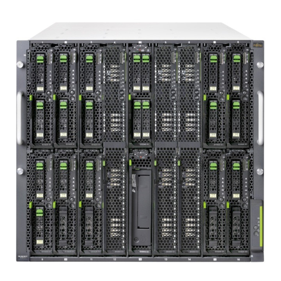
Appendix 13.1 Mechanical overview 13.1.1 System unit front Figure 71: PRIMERGY BX900 S2 system unit front Pos. Component Reference ID card "Removing / installing server blades and Server blades and storage storage blades" on page 54 and relevant blades operating manuals ServerView Local Service "Replacing the Local Service Display"... -
Page 176: System Unit Rear
CB 6 CB 7 CB 8 MMB 1 MMB 2 PSU 4 PSU 5 PSU 6 Figure 72: PRIMERGY BX900 S2 system unit rear Pos. Component Reference "Replacing a power supply unit" on PSU 1-6 PSUs and fan modules page "Replacing a fan module"... -
Page 177: System Unit Interior
Appendix 13.1.3 System unit interior Midplane Figure 73: Midplane Pos. Component Reference Server blade connectors "Replacing the midplane" on page 169 Front docking board connector Upgrade and Maintenance Manual BX900 S2... -
Page 178: Configuration Tables
Appendix Front docking board Figure 74: Front docking board Component Reference "Replacing the front docking board" on Front docking board page 160 13.2 Configuration tables 13.2.1 Server blade / storage blade fitting rules Please refer to chapter "Power supply" on page 85 and to the relevant server blade and storage blade operating manuals. -
Page 179: Connection Blade Fitting Rules And Port Assignment
Appendix 13.2.3 Connection blade fitting rules and port assignment Please refer to chapter "Connection blades" on page 105. 13.3 Connectors and indicators 13.3.1 Front of system Figure 75: Control and display elements on the front of the ServerView Local Service Display CSS indicator power indicator Global Error indicator... -
Page 180: Control Elements On The Local Service Display
Appendix Figure 76: ServerView Local Service Display The control elements and indicators can also be found on the front of the Local Service Display. This means they are also available when it is folded away. The control and display elements of the server blades and storage blades are described in the relevant operating manuals. -
Page 181: Leds On The Control Panel
Appendix Navigation buttons for the Local Service Display With the buttons you select a function. Pressing button executes the selected function. 13.3.1.2 LEDs on the control panel Power indicator (two-color) Lights up green when the system unit is switched on. Lights up orange when the system unit is switched OFF, but mains voltage is present (standby mode). - Page 182 Appendix CSS indicator (yellow) – Lights up yellow if a prefailure event was detected for a CSS component that you can fix yourself (for reasons of precaution) with the CSS concept. – Flashes yellow if an error was detected that you can fix yourself with the CSS concept.
-
Page 183: Back Of System
Appendix 13.3.2 Back of system 13.3.2.1 Connectors on the management blade Figure 77: Connectors on the management blade Service LAN port (as a point-to-point connection, for system unit administration only, no access to server blades and connection blades) USB ports for backing up and restoring the MMB configuration and for access to logging information Serial port for a local management console 4,5 LAN ports for blade server management (including server blades and... -
Page 184: Control Elements And Indicators On The Management Blade
Appendix 13.3.2.2 Control elements and indicators on the management blade 1 2 3 9 10 11 Figure 78: Control elements and indicators on the management blade Status indicator (yellow) Lights up when the management blade is active (master) Blinks when the management blade is defective. Is not lit when the management blade is not active (slave) LAN link indicators (service LAN port) Lights up green if a LAN connection exists. - Page 185 Appendix CSS indicator (yellow) – Lights up yellow if a prefailure event was detected for a CSS component that you can fix yourself (for reasons of precaution) with the CSS concept. – Flashes yellow if an error was detected that you can fix yourself with the CSS concept.
-
Page 186: Indicators On The Hot-Plug Power Supply Units
Appendix 13.3.2.3 Indicators on the hot-plug power supply units Figure 79: Indicators on the hot-plug standard PSU Figure 80: Indicators on the hot-plug HE PSU Error indicator for fan module 1 (orange) Lights up if fan module 1 is defective. Mains power indicator (two-color) Flashes green when the system unit is switched off but still connected to the mains (standby mode). -
Page 187: Indicators On The Fan Modules
Appendix Error indicator for fan module 2 (orange) Lights up if fan module 2 is defective. The following events are detected as predictable errors: The temperature is very high. The power consumption is very high. The current strength is very high. 13.3.2.4 Indicators on the fan modules 1 2 3 Figure 81: Indicators on fan module... -
Page 188: Indicators And Connectors Of The Connection Blades
Appendix 13.3.3 Indicators and connectors of the connection blades 13.3.3.1 Connection Blade GbE Switch/IBP 18/6 (SB6) Figure 82: Connection Blade GbE Switch/IBP 18/6 Status indicator (green/orange) Lights up green: Power supply is supplied to the connection blade Lights up Switch error orange: Dark: Power supply is not supplied to the connection blade... -
Page 189: Connection Blade Gbe Switch/Ibp 36/12 (Sb11A)
Appendix 13.3.3.2 Connection Blade GbE Switch/IBP 36/12 (SB11A) Figure 83: Connection Blade GbE Switch/IBP 36/12 ID indicator (blue) Lit: ID indicator was activated via the management blade Dark: Normal operation Status indicator (green/orange) Lights up green: power supply is supplied to the connection blade. Dark: power supply is not supplied to the connection blade. - Page 190 Appendix 1-Gbit Ethernet ports (8x, RJ45 with two integrated LAN status LEDs each) LAN transfer rate (green/orange) Lights up LAN transfer rate 1 Gbit/s orange: Lights up green: LAN transfer rate 100 Mbit/s Dark: LAN transfer rate 10 Mbit/s LAN connection indicator (green) Lit: LAN connection available Flashes:...
-
Page 191: Connection Blade Gbe Switch/Ibp 36/8+2 (Sb11)
Appendix 13.3.3.3 Connection Blade GbE Switch/IBP 36/8+2 (SB11) 1 2 3 4 5 Figure 84: Connection Blade GbE Switch/IBP 36/8+2 Status indicator (green/orange) Lights up green: Power supply is supplied to the connection blade Flashes orange: Connection blade error Dark: Power supply is not supplied to the connection blade ID indicator (blue) Lit:... - Page 192 Appendix HiGig/HiGig+ connection (CX4) for stacking (2x), for detailed information see section "Connection blade stacking" on page 137. 10-Gbit Ethernet ports for SFP+ modules for connecting fiber-optic or copper cables (with two integrated status LEDs each) 6 (ERR) Error indicator (orange) Dark: No SFP+ transceiver error Lit:...
-
Page 193: Connection Blade 10 Gbe Switch/Ibp 18/8
Appendix 13.3.3.4 Connection Blade 10 GbE Switch/IBP 18/8 1 2 3 Figure 85: Connection Blade 10 GbE Switch/IBP 18/8 Status indicator (green/orange) Lit green: Power supply is supplied to the connection blade Flashes Connection blade error alternately green/orange: Dark: Power supply is not supplied to the connection blade Stack indicator (green/yellow) (future use) Lit yellow: Operating as a stack master... - Page 194 Appendix 10-Gbit Ethernet ports for SFP+ modules for connection of fiber-optic cables or for active twinax copper cables (8x, each with two integrated status LEDs) 4 (ERR) Error indicator (orange) Dark: No SFP+ module error or SFP+ module not installed Lit: SFP+ module error Flashes:...
-
Page 195: Connection Blade Ethernet Pass Thru 10Gb 18/18
Appendix 13.3.3.5 Connection Blade Ethernet Pass Thru 10Gb 18/18 Figure 86: Connection Blade Ethernet Pass Thru 10Gb 18/18 ID indicator (blue) Lit: ID indicator was activated via the management blade Status indicator (green/orange) Lit green: Power is supplied to the connection blade Flashes orange: Connection blade error Dark:... -
Page 196: Connection Blade 8Gb Fc Switch 18/8
Appendix 13.3.3.6 Connection Blade 8Gb FC Switch 18/8 1 2 3 Figure 87: 8-Gb FC Switch Connection Blade 18/8 ID indicator (blue) Lit: ID indicator was activated via the management blade Health indicator (green/orange) Controlled by the management blade Reset button Status indicator (green/orange) Dark: Connection blade is not running or is defective... -
Page 197: Connection Blade 8Gb Fc Pass Thru 18/18
Appendix 13.3.3.7 Connection Blade 8Gb FC Pass Thru 18/18 Figure 88: 8-Gb FC Pass Thru Connection Blade 18/18 ID indicator (blue) Lit: ID indicator was activated via the management blade Status indicator (green/orange) Dark: Connection blade is powered off Lights up green: Connection blade is powered on, status OK Flashes orange: Connection blade is powered on, status fail... -
Page 198: Connection Blade Dcb Sw 10Gb 18/6+6
Appendix 13.3.3.8 Connection Blade DCB SW 10Gb 18/6+6 Figure 89: Connection Blade DCB SW 10Gb 18/6+6 External 10 Gb Ethernet ports (6x) Ports for Brocade branded Ethernet SFP+ 10 Gbit/s modules or SFP+ Twinax cables External 8 Gb FC ports (6x) Ports for Brocade branded FC SFP+ 8Gbit/s modules or SFP 4Gbit/s modules Status indicators for external Ethernet ports (green/orange) Dark:... - Page 199 Appendix ID indicator (blue) Lit: ID indicator was activated via the management blade Health indicator (green/orange) Dark: Connection blade is powered off or power has failed Lights up green: Connection blade is running Flashes orange Connection blade has failed Status indicator (green/orange) Dark: Connection blade is shut down and powered off normally Lights up green:...
-
Page 200: Connection Blade Fex B22F 10Gb (Cisco)
Appendix 13.3.3.9 Connection Blade FEX B22F 10Gb (Cisco) Figure 90: Connection Blade FEX B22F 10Gb (Cisco) External 10GbE ports (8x) to connect to the Nexus parent switch Ports for Cisco branded copper Twinax cables, Fabric Extender Transceivers (FET), or other standard 10 Gigabit Ethernet optics such as 10Gbase-SR, 10Gbase-LR, and 10Gbase-ER Service port (only for diagnostic purposes) ID indicator (blue) -
Page 201: Connection Blade Infiniband Switch 40 Gb 18/18
Appendix 13.3.3.10 Connection Blade Infiniband Switch 40 Gb 18/18 Figure 91: Connection Blade Infiniband Switch 40 Gb 18/18 Status indicator (green/yellow) Lights up green: Power supply is supplied to the connection blade Flashes yellow: Switch error ID indicator (blue) Lit: ID indicator was activated via the management blade Physical link status indicator of the external IB ports (green) Dark:... -
Page 202: Connection Blade Infiniband Switch 56 Gb 18/18 Fdr
Appendix 13.3.3.11 Connection Blade Infiniband Switch 56 Gb 18/18 FDR Figure 92: Connection Blade Infiniband Switch 56 Gb 18/18 FDR Status indicator (green/yellow) Lights up green: Power supply is supplied to the connection blade Flashes yellow: Switch error ID indicator (blue) Lit: ID indicator was activated via the management blade Physical link status indicator of the external IB ports (green) -
Page 203: Connection Blade Sas Switch 6 Gb 18/6
Appendix 13.3.3.12 Connection Blade SAS Switch 6 Gb 18/6 Figure 93: Connection Blade SAS Switch 6 Gb 18/6 Status indicator (green/orange) Lights up green: Power supply is supplied to the connection blade Lights up Switch error orange: Dark: Power supply is not supplied to the connection blade ID indicator (blue) Lit: ID indicator was activated via the management blade... -
Page 204: Management Blade Settings
Appendix 13.4 Management Blade Settings Figure 94: Management Blade DIP switch (a) The management blade is delivered with the DIP switches set in the following positions: Switch Function Default Flash Swap - activates the second management blade boot ROM. The second boot ROM can be used as reserve, if a management blade firmware update has failed. -
Page 205: Minimum Startup Configuration
Appendix 13.5 Minimum startup configuration Field Replaceable Units (FRU) If the system unit does not start up or other problems occur, it may be necessary to take the system down to its most basic configuration in order to isolate the defective component. - Page 206 Appendix Upgrade and Maintenance Manual BX900 S2...
Need help?
Do you have a question about the Primergy BX900 S2 and is the answer not in the manual?
Questions and answers