
Related Manuals for Fujitsu PRIMERGY BX900 S1


Summary of Contents for Fujitsu PRIMERGY BX900 S1
-
Page 1: Blade Server
Operating Manual - English PRIMERGY BX900 S1 Blade Server System Unit Operating Manual Edition March 2011... -
Page 2: Copyright And Trademarks
– The contents of this manual may be revised without prior notice. – Fujitsu assumes no liability for damages to third party copyrights or other rights arising from the use of any information in this manual. – No part of this manual may be reproduced in any form without the prior written permission of Fujitsu. - Page 3 It has not been designed or manufactured for uses which demand an extremely high level of safety and carry a direct and serious risk to life or body if such safety cannot be ensured. Operating Manual BX900 S1...
- Page 4 (hereafter, "high safety use"). Customers should not use this product for high safety use unless measures are in place for ensuring the level of safety demanded of such use. Please consult the sales staff of Fujitsu if intending to use this product for high safety use.
- Page 5 Only for the Japanese market: Although described in this manual, some sections do not apply to the Japanese market. These options and routines include: – USB Flash Module (UFM) – CSS (Customer Self Service) – Replacing the lithium battery BX900 S1 Operating Manual...
- Page 6 Operating Manual BX900 S1...
-
Page 7: Table Of Contents
Using cable ties ......55 Instructions for connecting/disconnecting cables ..56 BX900 S1 ....12 . - Page 8 Incorrect date and time ..... 81 Server blade does not boot ....81 7.10...
- Page 9 Index ........141 BX900 S1 .
- Page 10 Contents Operating Manual BX900 S1...
-
Page 11: Introduction
Additional security is provided by the lockable rack door. The BX900 S1 system unit takes up 10 height units (U) in the rack. Concept and target groups for this manual This operating manual describes how to install, set up and operate your server. -
Page 12: Documentation Overview
Technical data Documentation overview More information on your PRIMERGY BX900 S1 system unit can be found in the following documents: – "Quick Start Hardware - PRIMERGY BX900 S1" leaflet " はじめにお読みください -PRIMERGY BX900 S1" for the Japanese market (only included as a printed copy) –... -
Page 13: Performance Features
Your system unit is fitted with a ServerView Local Service Panel, which enables you to identify the type of component affected by the error directly on the server (for more information, see the "ServerView Suite Local Service Concept - LSC"... - Page 14 – 8 external 1-Gbit ports through RJ45 connections – 2 external 10-Gbit ports through SFP+ modules – 1 internal stacking port to the midplane of the BX900 S1 system unit – 1 external stacking port through a CX4 connection The stacking ports allow up to 8 SB11 connection blades to be switched together to form a so-called stack, see stacking"...
- Page 15 To use connection blade stacking, the firmware version of the management blade of the BX900 S1 system unit must be at least V4.27. This connection blade can be used in all connection blade slots. Ethernet connection blades in slots CB3/4 (fabric 2), CB5/6 (fabric 3) and CB7/8 (fabric 4) only support server blades that are fitted with an Ethernet mezzanine card.
- Page 16 (for details, see section "Connection blades" on page Information For the latest information on optional products provided for the BX900 S1 system unit see the configurator of the system unit: https://sp.ts.fujitsu.com/dmsp/docs/cnfgbx900-systemunits.pdf (for the EMEA market) http://primeserver.fujitsu.com/primergy/system.html...
- Page 17 Technical data Management blade The PRIMERGY BX900 S1 system unit has slots for two redundant, hot-swap management blades with an integrated management solution for complete remote administration of the system. The base configuration of the system unit contains one management blade (for details, see section "Management blades"...
- Page 18 Server management is implemented using the ServerView Operations Manager supplied and the PDA (Prefailure Detection and Analysis) technology from Fujitsu. PDA reports the threat of a system error or overload at an early stage, allowing preventive measures to be taken.
- Page 19 The redundant management blades and the optional remote test and diagnostics system ServerView Remote Management allows the PRIMERGY BX900 S1 blade servers to be serviced from a remote system. This enables remote diagnosis for system analysis, remote configuration and remote restart should the operating system or hardware fail.
-
Page 20: Notational Conventions
CAUTION! pay particular attention to texts marked with this symbol. Failure to observe this warning may endanger your life, destroy the system or lead to the loss of data. indicates additional information, notes and tips. Operating Manual BX900 S1... -
Page 21: Technical Data
Effective power Apparent power Heat dissipation Main power fuse Protection class BX900 S1 100 - 240 V 50 Hz - 60 Hz 230 V / 11.6 A (EMEA market) 100-120 V / 12 A (Japanese market) 200-140 V / 13.5 A (Japanese market) - Page 22 EN 61000-3-2 EN 61000-3-3 EN 55024, EN 300386 Low Voltage Directive 2006/95/EC (product safety) Electromagnetic compatibility 2004/108/EC EN 60721-3-3; class 3M2 ENEC GS, CE / CSA VCCI BSMI 446 mm 778.9 mm 438 mm / 10 HE Operating Manual BX900 S1...
- Page 23 Noise level Sound power level L Sound pressure level at adjacent workstation (ISO 9296) BX900 S1 EN 60721 / IEC 721 Part 3-3 EN 60721 / IEC 721 Part 3-2 5 °C ... 35 °C -20 °C ... 60 °C 10% ...
- Page 24 Technical data Operating Manual BX900 S1...
-
Page 25: Installation Steps, Overview
Installation steps, overview This chapter provides an overview of the installation steps for your BX900 S1 system unit. Links take you to sections where you can find more detailed information about the respective steps: Ê First read the chapter "Important notes"... - Page 26 Installation steps, overview Operating Manual BX900 S1...
-
Page 27: Important Notes
Notes and Regulations" or " 安全上のご注意 ". This device meets the relevant safety regulations for IT equipment. If you have any questions about whether you can install the server in the intended environment, please contact your sales outlet or our customer service team. - Page 28 (see "Ambient conditions" on page If the server has been moved from a cold environment, condensation may form both inside and on the outside of the machine. Wait until the server has acclimatized to room temperature and is absolutely dry before starting it up.
- Page 29 Always connect the device and the attached peripherals to the same power circuit. Otherwise you run the risk of losing data if, for example, a power outage occurs and the server is still running but the peripheral device (e.g. a storage subsystem) has failed.
- Page 30 You may only set the resolutions and refresh rates specified in the operating manual for your monitor. Otherwise, you may damage the monitor. If you are in any doubt, contact your sales outlet or customer service center. Operating Manual BX900 S1...
- Page 31 High humidity and airborne dust levels are to be avoided. Electric shocks and/or server failures may be caused by liquids such as water, or metallic items, such as paper clips, entering a drive.
- Page 32 The optical drive contains a light-emitting diode (LED), which under certain circumstances produces a laser beam stronger than laser class 1. Looking directly at this beam is dangerous. Never remove parts of the optical drive casing! Operating Manual BX900 S1...
- Page 33 When replacing the lithium battery in the management blade, always follow the instructions in the Service Supplement. When replacing the lithium battery in the server blade, always follow the instructions in the technical manual. All batteries containing pollutants are marked with a symbol (a crossed-out garbage can).
- Page 34 For a detailed description of how to handle ESD components, see the relevant European or international standards (EN 61340-5-1, ANSI/ESD S20.20). Other important information: During cleaning, observe the instructions in section unit" on page Operating Manual "Cleaning the system BX900 S1...
-
Page 35: Ce Conformity
Only unpack the system unit at the place where you want to set it up. Ask someone for help with carrying the system unit. Before lifting the system unit, remove all server blades, storage blades, connection blades, all power supply units and the fan modules to reduce the weight. -
Page 36: Notes On Installation Into The Rack
CAUTION! Because the system unit is heavy, at least three people are needed to safely mount the BX900 S1 system unit in the rack. (For the Japanese market, please refer to " 安全上のご注意 "). Before lifting the system unit, remove all server blades, all power supply units and the fan units to reduce the weight. -
Page 37: Environmental Protection
Important notes Environmental protection Environmentally-friendly product design and development This product has been designed in accordance with the Fujitsu standard for "environmentally friendly product design and development". This means that key factors such as durability, selection and labeling of materials, emissions, packaging, ease of dismantling and recycling have been taken into account. - Page 38 Details regarding the return and recycling of devices and consumables within Europe can also be found in the "Returning used devices" manual, via your local Fujitsu branch or from our recycling center in Paderborn: Fujitsu Technology Solutions Recycling Center D-33106 Paderborn Tel.
-
Page 39: Installing The Hardware
The server must not be exposed to extreme environmental conditions (see "Ambient conditions" on page humidity and heat. The server must be acclimatized to its operating environment for the time specified in the table before you operate it. Temperature difference (°C) Table 1: Acclimatization times In the table "Acclimatization... -
Page 40: Installation Procedure
"Unpacking the system unit" on section "Installing the system unit and configuration diagram on the order lists). section "Connecting devices 51). Please also read the section "Connecting the 52). Operating Manual section "Instructions chapter "Important notes" BX900 S1... -
Page 41: Installing The System Unit In The Rack
The rack can tip over if more than one unit is pulled out. Rack requirements The rack systems from Fujitsu PRIMECENTER Rack, DataCenter Rack and 19-inch standard rack (for the Japanese market) support the installation of PRIMERGY servers. Installation in most current rack systems from other manufacturers (3rd party racks) is also supported. - Page 42 – No cable management support (delivered with the mounting kit). – Climatic conditions. For ventilation of the installed server system, there must be an unrestricted air inlet on the front of the rack and an air outlet in the backplane of the rack.
- Page 43 Figure 2: Mechanical requirements Rack front Rack back Rack depth (comparison PRIMECENTER Rack 940/1000 mm) Rack width (comparison PRIMECENTER rack 700 mm) BX900 S1 Installing the hardware Operating Manual...
-
Page 44: Installation In Primecenter/Datacenter Rack
– General information regarding server installation in the rack is included in the technical manual for the appropriate rack. – For information on mounting of the server in the 19-inch standard rack (for the Japanese market) please refer to the "Rack mount guide". - Page 45 Ê Fasten the holding-down clamp at the upper end of the support bracket using two centering screws (2). Ê Fasten the second holding-down clamp at the same height as the first one to the rear left support upright using two centering screws. BX900 S1 Installing the hardware Operating Manual...
- Page 46 Ê Position the carrier rail in the front left support upright. Ê Fasten the carrier rail to the front support upright (3) using three M5 screws including plugwashers. Ê Repeat the operation for the right carrier rail. This rail does not require a support bracket. Operating Manual BX900 S1...
- Page 47 Figure 5: Position of the cage nuts Ê Fit the cage nuts for securing the server in the corresponding catches on the right and left support uprights. BX900 S1 Installing the hardware Operating Manual...
-
Page 48: Installing/Removing The System Unit
4.3.2 Installing/removing the system unit CAUTION! Because the PRIMERGY BX900 S1 system unit is large and heavy, at least three people are needed to safely mount it in the rack or remove it from the rack. Please observe the safety information and notes on rack installation in the chapter "Important notes"... - Page 49 Ê Lift the back end of the system unit onto the carrier rails in the rack. Ê Remove the back two carrying handles (1). Ê Push the system unit into the rack as far as the front carrying handles (2). Operating Manual BX900 S1...
- Page 50 Incorrect fitting of the system unit may lead to serious errors. Removing the system unit CAUTION! Make a note of the positions of the individual server blades, storage blades, connection blades, power supply units and fan modules in the system unit for reinstallation.
-
Page 51: Connecting Devices To The System Unit
USB ports for backing up and restoring the MMB configuration and for access to logging information Serial port for a local management console 4,5 LAN ports for blade server management (including server blades and connection blades) BX900 S1 Installing the hardware... -
Page 52: Cable Routing
Ê Connect the data cables according to the system configuration you require. Ports on the back of the system unit On the front of the system unit are the ports of the server blades for local administration. For information on these, see the operating manuals for the relevant server blades. - Page 53 (PSUs 4, 5 and 6) to the second source (phase). Thus 3+3 redundancy is supported; the system continues to run if one source fails, provided the remaining 3 power supplies are sufficient to deliver the required power. BX900 S1 Installing the hardware PSU 2 PSU 3...
- Page 54 With 3 power supply units, you must connect each one to a different source. Thus 2+1 redundancy is supported; the system continues to run if one source fails, provided the remaining 2 power supply units are sufficient to deliver the required power. Operating Manual BX900 S1...
-
Page 55: Using Cable Ties
If you wish, you can secure the power cable with a cable tie to prevent the C19 connector from being pulled out of the server accidentally. The cable tie is included in the accessories pack that is delivered together with the server. -
Page 56: Instructions For Connecting/Disconnecting Cables
Ê Unplug the power plugs of all affected devices from the power outlets or CEE sockets. Ê Connect all cables to the server and the peripherals. Secure the connectors of the data cables (e.g. by tightening the screws). Ê Plug all data transmission cables into the sockets provided for the data or telecommunication networks. -
Page 57: Installation And Operation
5.1.1 Front of system The BX900 S1 system unit has a fold-out ServerView local service panel on the front. It is controlled by the management blade and is used for local diagnostics and administration of the blade server. It is also used for the initial configuration... - Page 58 Figure 12: ID card in system unit The ID card contains various system information, such as the product name, serial number and order number (in the Japanese market, only the product name and the serial number). Operating Manual BX900 S1...
- Page 59 Figure 13: Locking the ServerView local service panel CAUTION! Press the touch point (see arrow) of the ServerView local service panel before you push it back into the frame of the system unit. BX900 S1 Installation and operation Operating Manual...
- Page 60 Installation and operation Figure 14: Control and display elements on the front of the ServerView local service panel CSS indicator Global Error indicator ID button On/Off button power-on indicator ID indicator Navigation buttons for the LocalView menu system Operating Manual BX900 S1...
-
Page 61: Control Elements
When the system is operating, pressing the On/Off button will switch off the system. CAUTION! Risk of loss of data! The On/Off button does not disconnect the server from the mains voltage. To disconnect from the mains completely, remove the power plug(s). ID button Lights up (blue) on the front and on the rear of the system unit when the ID button is pressed. - Page 62 The ID indicator can also be activated via the Management Blade Web interface and via the ServerView Operations Manager and the iRMC S2 Web interface and its status reported to the ServerView Operations Manager and the iRMC S2. Operating Manual "Customer Self BX900 S1...
-
Page 63: Back Of System
Flashes orange when a LAN transfer is in progress. LAN transfer-rate indicator (service LAN port) Lights up green for a LAN transfer rate of 100 Mbit/s. Does not light up for a LAN transfer rate of 10 Mbit/s. BX900 S1 Installation and operation Operating Manual 9 10 11... - Page 64 (CSS)" on page Identification (ID) button with ID LED (blue) ID indicators on the front and rear of the server light up when the ID button is pressed. The two ID indicators are synchronized. To deactivate, press the button again.
- Page 65 Lights yellow for a LAN transfer rate of 1 Gbit/s. Lights up orange for a LAN transfer rate of 100 Mbit/s. Does not light up for a LAN transfer rate of 10 Mbit/s. Hidden reset button BX900 S1 Installation and operation Operating Manual...
-
Page 66: Indicators On The Hot-Plug Power Supply Units
Error indicator for fan module 2 (orange) Lights up if fan module 2 is defective. The following events are detected as predictable errors: The temperature is very high. The power consumption is very high. The current strength is very high. Operating Manual BX900 S1... -
Page 67: Indicators On The Hot-Plug Fans
Lights up green when the system unit is switched on and the fan module is working properly. Error indicator for fan module 2 (orange) Lights up if fan module 2 is defective. BX900 S1 Installation and operation 1 2 3 Operating Manual... -
Page 68: Switching The System Unit On/Off
CAUTION! Before switching the system unit on using the On/Off button, the PRIMERGY BX900 S1 system unit must be connected to the power supply for at least a minute. If you switch on the system unit and the connected monitor only shows flickering stripes, switch it back off immediately (see "Troubleshooting and tips"... - Page 69 Ê To properly shut down all server blades, press the On/Off button on the front of the system unit (position 4 in server blades will then be shut down. Ê To immediately shut down all server blades, press the On/Off button on the front of the system unit (position 4 in All server blades are switched off immediately.
-
Page 70: Configuring Management Blades
This section explains how to do the initial configuration of the management blades. For more information on administration of the blade server, see the manual "PRIMERGY BX900 Blade Server Systems ServerView Management Blade S1 User Interface Description". - Page 71 The wizard guides you step by step through the menus, in which you make the necessary settings for putting the blade server into operation. You operate the wizard with the Previous, Next, and Cancel buttons. The Finish button closes it.
- Page 72 This test begins automatically after switch-on or after a hardware replacement. If errors are found, you can find out more about them via the Details button. Replace the defective hardware component and repeat the test. Operating Manual BX900 S1...
- Page 73 USB storage medium. You can export the following parameters: – Language – Identification – Network – PIN – Power BX900 S1 Installation and operation Operating Manual...
-
Page 74: Cleaning The System Unit
You may clean the housing surface of the system unit with a dry cloth. If it is very dirty you can use a damp cloth that has been dipped in water with a mild detergent and well wrung out. Operating Manual BX900 S1... -
Page 75: Property And Data Protection
Property and data protection The blade server is protected against unauthorized access by the lockable rack door. To protect the system and data internally against unauthorized access, you can activate the security functions of the management blade. For more information, see the manual "PRIMERGY BX900 Blade Server Systems ServerView... - Page 76 Property and data protection Operating Manual BX900 S1...
-
Page 77: Troubleshooting And Tips
Ê Make a note of the steps you have taken and the situation in which the fault occurred. Also make a note of the error messages displayed. Ê Switch off the defective server blade or the system. Ê Contact customer service. -
Page 78: Front Or Back Error Led Flashes Orange
"Installing a connection blade" on page 57), one of the following errors may have occurred: figure "Indicators on the hot-plug 66): 135). section "Replacing a fan unit" on page 120). Operating Manual section "Control and section "Replacing the section "Hot-plug 138). section BX900 S1... -
Page 79: System Switches Itself Off
Ê Check that the power cable is properly connected to the monitor and the power outlet. Ê Check that the data cable is properly connected to the system and the monitor (if it is plugged in with a connector). Ê Switch on your monitor. BX900 S1 Troubleshooting and tips Operating Manual... -
Page 80: Flickering Stripes On Monitor Screen
Ê Check whether the mouse driver is properly installed and is activated when the application program is started. Detailed information can be found in the user manuals for the mouse, the operating system and the application program. Operating Manual BX900 S1... -
Page 81: Incorrect Date And Time
Change the battery as described in the manual for the relevant server blade. Server blade does not boot The server blade does not boot after a defective hard disk drive was replaced Incorrect SCSI configuration (onboard SCSI HostRAID controller) Ê... -
Page 82: Defective Drive
For information see the documentation for the RAID controller (on the ServerView Suite DVD 2 under "Controllers"). Ê Remove and reinstall the drive while the system is switched ON. If the drive continues to be shown as defective, then replace it. Operating Manual BX900 S1... -
Page 83: Hot-Plug Components
10 11 12 18 Figure 19: Numbering of the server blade slots The PRIMERGY BX900 S1 system unit has 18 slots on the front in two rows for server blades. Slots 2, 17, 7, 10, 18 and 15 can alternatively be fitted with storage blades. - Page 84 When you install a server blade in an active system unit, the server blade automatically performs a Power-On Self-Test (POST) and then switches itself off. If the system unit is switched off when you install the server blade, the automatic POST is performed immediately after you switch on the system unit.
- Page 85 Figure 20: Installing the BX920 S1 server blade Ê Undo the locking mechanism of the release lever (1). Ê Open the release lever (2). Ê Push the server blade as far as possible into the empty slot (3). Operating Manual BX900 S1...
- Page 86 Removal is carried out in reverse order. Installing a single height / double width Blade The following describes how to install a BX960 S1 server blade. This server blade occupies 2 bays one upon the other in the BX900 S1 system unit. Operating Manual BX900 S1...
- Page 87 Figure 22: Installing a BX960 S1 server blade Ê Undo the locking mechanism of the release lever (1). Ê Open the release lever (2). Ê Push the server blade as far as possible into the empty slot (3). BX900 S1 Operating Manual...
- Page 88 Removal is carried out in reverse order. Installing a dummy server blade module Any unused server blade slots must be fitted with dummy modules to comply with EMC regulations for the system and to ensure sufficient cooling of the components.
- Page 89 (see figure 25 on page 89). Figure 25: Installing a dummy server blade module Ê Push the dummy server blade into the empty slot until it clicks into place. Operating Manual BX900 S1...
- Page 90 Hot-plug components Removing a dummy server blade module Ê Push up the release lever (1) and pull the dummy module out of the slot by its handle. Operating Manual BX900 S1...
-
Page 91: Connection Blades
Connection blades The PRIMERGY BX900 S1 system unit has 8 slots on the back for connection blades for connecting the server blades to LAN and SAN networks. This section deals with the connection blades available for your BX900 S1 system unit. It describes their most important features, the external ports, the assignment of the internal ports to the server blades, and how to install and remove connection blades in/from the system unit. -
Page 92: Connection Blade Gbe Switch/Ibp 36/12 (Sb11A)
"Connection blade slots" on page If the connection blade is installed in one of the slots CB 3/4, CB 5/6 or CB 7/8, the server blades must have corresponding GbE mezzanine cards. For more information, see the operating manuals for the relevant server blades. -
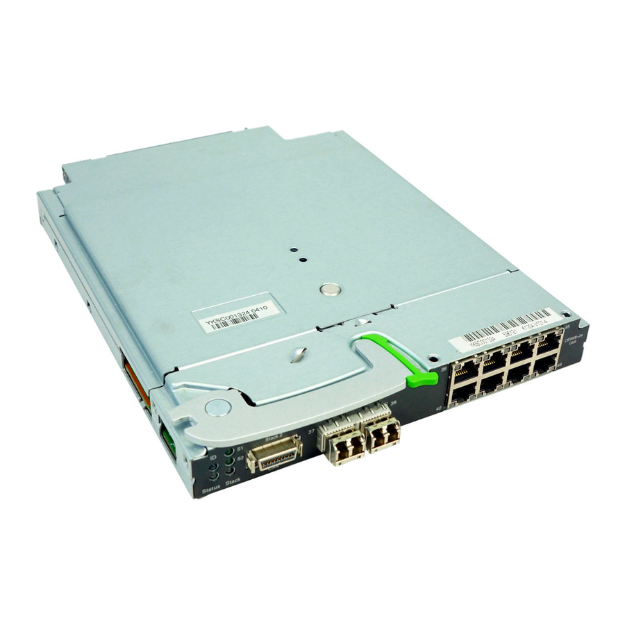
Page 93: Connection Blade Gbe Switch/Ibp 36/8+2 (Sb11)
The Connection Blade GbE Switch/IBP 36/8+2 can be used as a layer-2 switch or an Intelligent Blade Panel (IBP). It provides the following connections: – 36 internal 1-Gbit ports to the server blades – 8 external 1-Gbit ports through RJ45 connections –... - Page 94 Hot-plug components – 1 internal stacking port to the midplane of the BX900 S1 system unit – 1 external stacking port through a CX4 connection The stacking ports allow up to 8 SB11 connection blades to be switched together to form a so-called stack, see...
- Page 95 Flashes: 7 (LINK) LAN connection indicator (green) Lit: Flashes: Dark: BX900 S1 Power supply is not supplied to the connection blade ID LED was activated via the management blade Normal operation Stacking port 1 is available Stacking port 1 is active...
-
Page 96: Connection Blade Stacking
The connections within a stack are established through the stacking ports of the connection blades. The internal stacking ports to the midplane of the BX900 S1 system unit are each used to connect two connection blades that are installed in the same fabric, i.e. - Page 97 The stacking connections within a stack must form a circuit. Connection blade stacks can be formed within a BX900 S1 system unit, across several system units of a rack or across several system units in different racks. The possible cabling scenarios are shown in the following diagrams, with the...
- Page 98 36/8+2 if these belong to a stack with other connection blades. In addition, the management blade of the system unit and the iRMCs of the relevant server blades must have specific firmware versions - management blade: 4.27 or higher; iRMC: 4.76G or higher.
- Page 99 Fabric 4 Fabric 1 Fabric 2 Fabric 3 Fabric 4 Fabric 1 Fabric 2 Fabric 3 Fabric 4 Figure 33: Stack with 8 connection blades in 4 system units in a rack (variant 1) BX900 S1 Operating Manual Hot-plug components...
- Page 100 Fabric 3 Fabric 4 Fabric 1 Fabric 2 Fabric 3 Fabric 4 Fabric 1 Fabric 2 Fabric 3 Fabric 4 Figure 34: Stack with 8 connection blades in 4 system units in a rack (variant 2) Operating Manual BX900 S1...
- Page 101 Supported combinations for connection blade stacks The following table shows the possible combinations of connection blade stacks. Columns a - f contain permissible numbers and distributions of the connection blades for the different combinations of BX900 S1 system units and racks. Rack (R) BX900 (Z)
- Page 102 For more detailed information and additional possible configurations, see the manuals "PRIMERGY BX900 Blade Server Systems – Ethernet Connection Blade Module IBP Version – User’s Guide", "PRIMERGY BX900 Blade Server Systems – Ethernet Connection Blade Module Switch Version – User’s Guide"...
-
Page 103: Connection Blade 10 Gbe Switch/Ibp 18/8
116. The server blades must have corresponding 10 GbE mezzanine cards. For more information, see the operating manuals for the relevant server blades and the manual "PRIMERGY 10GbE Connection Blade 18/8 User Guide" and " ス イッチブレード 10Gbps 18/8 取扱説明書 "(for the Japanese market). - Page 104 ID LED was activated via the management blade Normal operation No SFP+ module error or SFP+ module not installed SFP+ module error SFP+ module not supported LAN connection available LAN connection active LAN connection unavailable or deactivated Operating Manual BX900 S1...
-
Page 105: Connection Blade 8Gb Fc Switch 18/8
The 8-Gb FC Switch Connection Blade 18/8 14 (Brocade BR5450) provides the following connections: – 18 internal 8-Gbit ports to the server blades – 8 external Fibre Channel ports via 4-Gbit SFP or 8-Gbit SFP+ modules This connection blade can be used in slots CB 3/4 and CB 5/6, see figure "Connection blade slots"... - Page 106 Lights up orange: Signal reception, but not online Flashes orange: Slow (~ 2 sec. interval): FC port deactivated. Fast (~ 0.5 sec. interval): FC port defective Management LAN port Slow: FC port online, but segmented Fast: Internal loop Operating Manual BX900 S1...
-
Page 107: Connection Blade Ethernet Pass Thru 10Gb 18/18
The Connection Blade Ethernet Pass Thru 10Gb 18/18 provides the following connections: – 18 internal ports to the server blades at 10 Gbit/s and 1 Gbit/s link speed – 18 external uplink ports at 10 Gbit/s and 1 Gbit/s link speed through... - Page 108 Link is up and data transfer External ports (18x) Ports for Ethernet through SFP/SFP+ modules Server blade not present, powered down, or link is inactive Uplink port module not present Uplink port cable not connected One or both of the internal and/or external links is down...
- Page 109 The configuration of the connection blade is controlled by the management blade. Each port group can be configured to a certain link protocol. The management blade web interface allows the user to modify the port group link speed configuration. BX900 S1 Operating Manual Hot-plug components...
-
Page 110: Connection Blade 8Gb Fc Pass Thru 18/18
The 8-Gb FC Pass Thru Connection Blade 18/18 provides the following connections: – 18 internal 8-Gbit ports to the server blades – 18 external Fibre Channel ports via 4-Gbit SFP or 8-Gbit SFP+ modules This connection blade can be used in slots CB 3/4 and CB 5/6, see "Connection blade slots"... - Page 111 Port assignment Each of the 18 server blades of a BX900 S1 system unit can be equipped with 2 FC mezzanine cards each with 2 ports (0, 1). Each of the server blade FC ports is connected to a dedicated port of an FC pass thru connection blade in a defined connection blade slot.
-
Page 112: Connection Blade Infiniband Switch 40 Gb 18/18
The Connection Blade Infiniband Switch 40Gb 18/18 provides the following connections: – 18 internal 40-Gbit Infiniband ports to the server blades – 18 external 40-Gbit Infiniband connections through QSFP modules This connection blade can be used in slots CB 3/4, CB 5/6 and CB 7/8, see figure "Connection blade slots"... - Page 113 IB port online Logical link status indicator of the external IB ports (yellow) Dark: No signal reception Lights up yellow: IB port online Flashes yellow: Data transport External IB ports (18x) Ports for QSFP plugs BX900 S1 Operating Manual Hot-plug components...
-
Page 114: Connection Blade Gbe Switch/Ibp 18/6 (Sb6)
This connection blade can be used in all connection blade slots. If the connection blade is installed in one of the slots CB 3/4, CB 5/6 or CB 7/8, the server blades must have corresponding GbE mezzanine cards. For more information, see the operating manuals for the relevant server blades. - Page 115 Lights up green: LAN transfer rate 100 Mbit/s Dark: LAN connection indicator (green) Lit: Flashes: Dark: BX900 S1 Switch error Power supply is not supplied to the connection blade ID LED was activated via the management blade Normal operation LAN transfer rate 1 Gbit/s...
-
Page 116: Fitting Rules For Connection Blades
Hot-plug components 8.2.9 Fitting rules for connection blades The connection blade slots of the BX900 S1 system unit are numbered as follows. Fabric 1 Fabric 2 Fabric 3 Fabric 4 Figure 41: Connection blade slots Each pair of adjacent connection blade slots forms a so-called fabric. The... - Page 117 The two connection blades within a fabric must have the same technology, i.e. either Ethernet or Fibre Channel or Infiniband. When filling the slots in fabrics 2, 3 and 4, also make sure the server blades are fitted with the appropriate mezzanine cards. The following rules apply for fitting...
-
Page 118: 8.2.10 Port Assignment Of The Connection Blades
Hot-plug components 8.2.10 Port assignment of the connection blades The A-channels of the controllers in the server blades are connected to the connection blade slots on the left-hand side (CB1, CB3, CB5 and CB7). The B- channels are connected to the slots on the right-hand side (CB2, CB4, CB6 and CB8). - Page 119 Hot-plug components For more information on configuring the connection blades, see the manual "PRIMERGY BX900 Blade Server Systems ServerView Management Blade S1 User Interface Description" and the documentation for the relevant connection blades. Operating Manual BX900 S1...
-
Page 120: 8.2.11 Installing A Connection Blade
(EMC) regulations and to ensure sufficient cooling of the system components. Figure 42: Dummy connection blade module To add connection blades, you must first remove the dummy modules from the relevant slots. section "Safety instructions" on Operating Manual BX900 S1... - Page 121 Installing a single-width connection blade CAUTION! Make sure you observe the safety notes and the information on handling electrostatic-sensitive devices in the section Sensitive Devices" on page Ê Unpack the connection blade. BX900 S1 "Modules with Electrostatic- Operating Manual Hot-plug components...
- Page 122 Figure 45: Locking the connection blade Ê Push the connection blade into the slot as far as it will go. Ê Push the release lever in the direction of the arrow until it clicks into place. Operating Manual BX900 S1...
- Page 123 Ê Remove the separating clip by pressing the little black lever (see blow-up in figure 46) to the left and pulling out the separating clip. BX900 S1 "Modules with Electrostatic- Operating Manual Hot-plug components...
- Page 124 If you remove a double-width connection blade and do not replace it with a new one, you must install the separating clip (see dummy modules in the empty slot, see page 120. Operating Manual page 123) and two BX900 S1...
-
Page 125: Management Blades
Management blades Figure 49: management blade The PRIMERGY BX900 S1 system unit has slots for two redundant, hot-swap management blades with an integrated management solution for complete remote administration of the system. The basic configuration of the BX900 S1 system unit contains one management blade. -
Page 126: Hot-Plug Power Supply Units
Hot-plug components Hot-plug power supply units The BX900 S1 system unit has 6 bays for hot-plug power supply units (PSU 1-6). All bays for power supply units are fitted with flaps which close automatically. This ensures sufficient cooling of the system components when you replace a power supply unit or fan module during operation and when there are empty bays. -
Page 127: Fitting Rules For Power Supply Units And Fan Modules
Redundant configurations with 2 basic PSUs (2+1 and 2+2) make only sense with 200 … 240 VAC input voltage. Example: A BX900 S1 system unit with 3 standard PSUs at 230 VAC and one fan can support a maximum of 10 BX920 S2 server blades or 5 BX960 S1 server blades. - Page 128 5 + 1 6 + 0 Table 4: Fitting rules for Standard PSUs connected to 200 ... 240 VAC BX922 S2 with CPU 95 W 130 W Operating Manual BX924 S2 BX960 S1 with CPU 95 W 130 W BX900 S1...
- Page 129 3 + 0 3 + 0 3 + 0 3 + 0 3 + 1 Table 6: Fitting rules for Standard PSUs (Japan Version) connected to 100 ... 120 VAC BX900 S1 BX922 S2 with CPU 95 W 130 W BX922 S2...
- Page 130 200 - 240V; in other regions with lower single-phase voltage, two phases have to be coupled, which means that full phase redundancy is not possible. BX922 S2 with CPU 95 W 130 W Operating Manual BX924 S2 BX960 S1 with CPU 95 W 130 W BX900 S1...
-
Page 131: Configuration Examples
8.4.1.1 Configuration examples The BX900 S1 system unit is divided into 6 cooling zones. To achieve optimum cooling of all components, the 6 cooling zones on the front and back of the system unit must be fitted equally. The following examples show how the various configurations of slots for power supply units and fan modules as well as for server blades and/or storage blades should be fitted. - Page 132 PSU 4 PSU 5 Zone 6 Zone 4 Zone 1 Zone 1 PSU 3 PSU 6 10 11 12 18 13 14 15 16 Zone 2 Zone 2 Operating Manual Zone 3 Zone 5 Zone 4 Zone 6 BX900 S1...
- Page 133 Zone 5 Zone 3 PSU 1 PSU 2 PSU 4 PSU 5 Zone 6 Zone 4 BX900 S1 Zone 1 Zone 1 PSU 3 PSU 6 10 11 12 18 13 14 15 16 Zone 2 Zone 2 Operating Manual...
- Page 134 PSU 4 PSU 5 Zone 6 Zone 4 Zone 1 Zone 1 PSU 3 PSU 6 10 11 12 18 13 14 15 16 Zone 2 Zone 2 Operating Manual Zone 3 Zone 5 Zone 4 Zone 6 BX900 S1...
-
Page 135: Replacing The Power Supply Unit
Ê First unplug the power cable of the defective power supply unit from the mains. Ê Unplug the power cable from the insulated socket of the defective power supply unit. Figure 51: Open release lever Ê Unlock the locking lever (1) and open the release lever (2). BX900 S1 Operating Manual Hot-plug components... - Page 136 Ê Pull the power supply unit out of its bay. Installation is carried out in the reverse order. Figure 53: Power supply unit in the bottom bays In the bottom bays (PSU 4-6), the power supply units are installed upside down, see figure above. Operating Manual BX900 S1...
-
Page 137: Hot-Plug Fan Modules
Hot-plug fan modules The PSU bays of the BX900 S1 system unit can alternatively be fitted with hot- plug fan modules. Figure 54: Fan module Whether and how many fan modules need to be installed depends on the number of server blades installed and on the redundant power supply... -
Page 138: Replacing A Fan Unit
Figure 55: Fan units in a power supply unit Figure 56: Removing a fan unit Ê Press the green locking elements inward (1) and pull the fan unit out of the housing (2). Operating Manual BX900 S1... - Page 139 Ê Insert the fan unit such that the airflow is directed out of the back of the system unit. The airflow arrow must point to the side with the display elements of the power supply unit or fan module. BX900 S1 Operating Manual Hot-plug components...
- Page 140 Hot-plug components Operating Manual BX900 S1...
-
Page 141: Index
120, stacking connection blades fitting rules port assignment consumables BX900 S1 control elements system cooling fan in power supply unit fan module CSS indicator 62, data manipulation data protection date incorrect... - Page 142 (LED) Lithium battery Low Voltage Directive 22, mains connect system management blade meaning of the symbols monitor display drifts flickering lines no screen display mouse no pointer on screen Operating Manual BX900 S1...
- Page 143 Infiniband connection blade replace power supply unit return of devices Safety instructions safety standards saving energy screen remains dark security function BX900 S1 server data protection dimensions electrical data noise level power on indicator property protection service transport server blade...
- Page 144 Index Technical data technical data ambient conditions time incorrect touch point transport damage type label unpack system Operating Manual BX900 S1...
Need help?
Do you have a question about the PRIMERGY BX900 S1 and is the answer not in the manual?
Questions and answers