Table of Contents
Advertisement
Quick Links
MANUFACTURED BY:
ISO-9001
AN
6,WU-CHUAN RD.,HSIN-CHUANG TEL: 886-2-2991599 (REP.) FAX: 886-2-2991819, 2991808
(WU-KU INDUSTRIAL ZONE)
TAIPEI HSIEN, TAIWAN
HT-3200 /
PB-3200 SERIES
TECHNICAL MANUAL
Rev. : Original
POSIFLEX TECHNOLOGY, INC.
ISO-14001
AND
http://www.posiflex.com
http://www.posiflexusa.com
CERTIFIED MANUFACTURER
http://www.posiflex.com.tw
EMAIL: posiflex@posiflex.com.tw
Advertisement
Table of Contents

Subscribe to Our Youtube Channel
Related Manuals for POSIFLEX HT-3200 SERIES


Summary of Contents for POSIFLEX HT-3200 SERIES
- Page 1 HT-3200 / PB-3200 SERIES TECHNICAL MANUAL Rev. : Original POSIFLEX TECHNOLOGY, INC. MANUFACTURED BY: ISO-9001 ISO-14001 CERTIFIED MANUFACTURER 6,WU-CHUAN RD.,HSIN-CHUANG TEL: 886-2-2991599 (REP.) FAX: 886-2-2991819, 2991808 (WU-KU INDUSTRIAL ZONE) http://www.posiflex.com http://www.posiflex.com.tw TAIPEI HSIEN, TAIWAN http://www.posiflexusa.com EMAIL: posiflex@posiflex.com.tw...
-
Page 2: About This Manual
All rights are strictly reserved. No part of this documentation may be reproduced, stored in a retrieval system, or transmitted in any form or by any means, electronic, mechanical, photocopying, or otherwise, without the prior written consent of Posiflex Technology, Inc. the publisher of this documentation. TRADE MARKS AND SERVICE MARKS POSIFLEX is a registered trademark of Posiflex Technology, Inc.. -
Page 3: Table Of Contents
CONTENTS OVERVIEW ............................5 SCOPE............................. 5 FEATURES ............................. 5 OPTIONAL ITEMS......................... 6 GENERAL SPECIFICATION ......................7 SYSTEM ............................7 POWER SOURCE........................... 7 SYSTEM POWER ON/OFF CONTROL ..................8 12VDC POWER SUPPLY INTO SYSTEM..................8 OVERALL POWER OUTPUT LIMIT.................... 8 INPUT / OUTPUT PORTS......................8 TOUCH PANEL (F HT-3200 O ) .................. - Page 4 SOFTWARE SWITCH OFF ...................... 30 FORCED SWITCH OFF......................30 AUTOMATIC POWER ON CONTROL..................32 ALARM CLOCK WAKE UP...................... 32 MODEM RING UP ........................32 LAN WAKE UP ......................... 33 FINGERPRINT SENSOR ......................33 POSIFLEX TOOLS ........................34 POSIFLEX POWER SWITCH MANAGER ................34...
- Page 5 POSIFLEX MSR MANAGER ....................35 PROGRAMMABLE KEYPAD....................38 POSIFLEX USB TOUCH MANAGER ..................40 HARDWARE DETAILS........................43 MAIN BOARD (HT-3200)......................43 COMPONENT SIDE......................... 43 JUMPERS AND CONNECTORS ....................44 JUMPER SETTINGS......................... 45 SERIAL ADAPTOR CARD HT-022..................... 47 JUMPERS AND CONNECTORS ....................47 JUMPER SETTINGS.........................
- Page 6 RELEASE SATA HDD ......................59 DISPLAY ADAPTOR BOARD (For PB-3200 only) ............59 REPLACE MAINBOARD......................60 SPARE PARTS LIST ......................... 60 SPARE PARTS LIST ......................... 61 ASSEMBLY DRAWING......................65...
-
Page 7: Overview
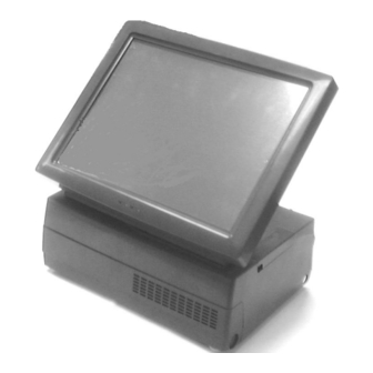
PC application software and development tools that are now inexpensively available and abundant. For the HT-3200 series terminal is powered by most up to date CPU and provides a color TFT LCD screen with a resistive type touch control panel on sturdy and easily adjustable structure on top of the main unit. -
Page 8: Optional Items
+12V power on COM2/3/4 by jumper setting. The COM2/3/4 is default as no power at delivery. Parallel Port: Each HT/PB-3200 system is equipped with a parallel port that supports SPP/EPP/ECP. VGA Port: There is a VGA connector for connection of external monitor with + 12 V DC power supply included. -
Page 9: General Specification
g) SSD HDD h) 2 SATA HDD with RAID control board. UPS battery. GENERAL SPECIFICATION SYSTEM CPU: Intel Atom N270 1.6GHz. RAM: DIMM socket * 2 ,DDR-2 533MHz ,Max 2 GB 2.5” HDD in SATA interface. POWER SOURCE DC power adaptor: Item Specification Voltage range of power input... -
Page 10: System Power On/Off Control
SYSTEM POWER ON/OFF CONTROL One main power ON/OFF push switch at side, this switch can be programmed as “ON” only System can be waked up after each power off by any of the preset timer or a remote COM port MODEM call or LAN wakeup packet. Please notice that when wake up by LAN or modem ring up available, HT/PB-3200 does not support EUP standard. -
Page 11: Touch Panel (For Ht-3200 Only)
6 x USB ports 4 x serial communication ports. COM 2/3/4 each can supply DC +5V through pin 9. 1 x CR port 1 x mini DIN 4 pin power input jack Optional COM 5/6 ports TOUCH PANEL (For HT-3200 Only) Extremely endurable life survives minimum up to 35,000,000 touches at same spot Touch control interface: USB... -
Page 12: Led Indicator In Lcd Panel
LED INDICATOR IN LCD PANEL Power ON / Standby LED: blue/orange dual color for system ON/OFF status, external power status, LAN status LED: yellow/green dual color for link, communication (green: LAN link; steady green with flickering yellow: data transmission) EXTERIOR HT-3200 DIMENSIONS: LCD @ 15°: 295 mm (W) x 263 mm (D) x 342 mm (H) or... -
Page 13: Compliance Approvals
HUMIDITY RANGE: Operating: 20%RH ~ 80%RH, non-condensing, max. wet bulb 26°C (78.8°F) Non-operating: 10%RH ~ 80%RH, non-condensing, max. wet bulb 28.9°C (84.0°F) COMPLIANCE APPROVALS Whole system meet CE, FCC class A standard (Meet IEC61000-4-2/-3/-4/-5/-6/-8/-11) Power supply is UL, VDE approved RoHS OPTIONS SECOND DISPLAY ON BASE... -
Page 14: Customer Display Upgrade Kit
CUSTOMER DISPLAY UPGRADE KIT MODEL Number PD-2601/U PD-307/U PD-7621 Display Media Number of rows Characters per row 15 or 30 Character width (mm) 5.25 4.27 or 8.47 Character height (mm) 9.03 9.66 8.47 Character format 5 X 7 8 x 16 or 16 x 16 Character code pages International character sets Command modes... -
Page 15: Side Mount Upgrade Kit Sd300
Functions include: 36 keys + key-lock programmable keypad, MSR, smart card reader Interface: USB PROGRAMMABLE KEYPAD: 1 electronic 6-position control key to lock up or determine among 5 different pages of programmable keys 16 key numeric keypad with a double sized “Enter” key 20 programmable single keys of size 19 x 19 mm MAGNETIC STRIPE READER: Reader head options: ISO 2 tracks (track 1 + track 2);... -
Page 16: Cash Drawer Control Cable
CASH DRAWER CONTROL CABLE 2 in 1 cash drawer control cable 20863023400 for independent control over two cash drawers of CR-2200 /CR-3100 /CR-3200 /CR-4000 /CR-4100 /CR-6310 WIRELESS LAN IEEE 802.11b/g with USB interface SSD HDD 2.5” SATA interface SSD can’t coexist with HDD in main unit PRINTER: PP-2000 1. - Page 17 9. Built-in character registration function with 256 KB flash memory for downloading and storing special character pattern or graphics for store logo 10. Supports option either alarm type or buzzer type kitchen alarm PP-5600 1. Dot matrix impact 9 pin 2.
- Page 18 8. Default with serial interface, option for parallel, USB, WI-FI or LAN interface by plug in module. PP-8000 1. Supports UPOS 1.8 2. WEPOS compliant 3. High speed thermal line printer up to 220 mm/sec 4. High resolution 8 dots/mm by 512 dots/line (576 dots max.) 5.
-
Page 19: Reliability Information
RELIABILITY INFORMATION TOUCH PANEL LIFE EXPECTANCY (TOUCHES AT SAME SPOT): RESISTIVE TYPE: 35,000,000 UP MSR LIFE EXPECTANCY: 500,000 PASSES WHOLE SYSTEM MTBF: 50,000 Hrs at 90% confidence level. -
Page 20: System Definitions
SYSTEM DEFINITIONS BLOCK DIAGRAM PS/2 PS/2 Touch Panel Mouse Port Mouse Touch Signal Controller LCD & Touch Connector LCD Panel LM-2010 PS/2 KB PS/2 Port (+12V) Port screen for HT series) 12 V DC PSU Circuit DDR2 533 Adaptor DIMM Intel Atom N270 1/3/5 Devices... -
Page 21: 12 V Dc In Connector
12 V DC IN CONNECTOR PIN ASSIGNMENT OF 4 PIN PLUG: PIN # DEFINITION +12 V +12 V CASE CASE CHASSIS GND LAN PORT PIN ASSIGNMENT OF 8 PIN TELEPHONE JACK: PIN # DEFINITION PIN 1 TD1 + TD1 - TD2 + TD2 - TD3 +... -
Page 22: Vga Connector
VGA CONNECTOR This port is a standard 3 x 5 D-sub VGA connector PIN # DEFINITION PIN # DEFINITION PIN # DEFINITION NCID0 GREEN DDC_DATAID1 BLUE HSYNC NCID2 NC/+12VKEY VSYNC DDC_CLKID3 SERIAL PORT COM1 PIN ASSIGNMENT OF 9 PIN D SUB MALE CONNECTOR: PIN # DEFINITION ALTERNATIVE DEFAULT SETTING... -
Page 23: Serial Port Com2/3/4
Please remember that if there is no need for power supply in these I/O ports, please disable these functions. PIN 1 CAUTION: VGA port +12V is dedicate design for Posiflex 2 monitors implementation only. It must disable this power when this VGA port connect to other monitor, otherwise the monitor will burn out. -
Page 24: Parallel Port Lpt1
PARALLEL PORT LPT1 PIN ASSIGNMENT OF 25 PIN D SUB FEMALE CONNECTOR: PIN # SPP MODE EPP MODE ECP MODE - STROBE -WRITE -STROBE - ACK INTR -ACK BUSY -WAIT BUSY, PeriphAck Perror, -AckReverse SLCT SLCT - AUTO FEED -Datastb -AutoFeed, HostAck - ERROR -Fault, -PeriphRequest... -
Page 25: Ps/2 Keyboard Connector
PS/2 KEYBOARD CONNECTOR PIN ASSIGNMENT OF 6 PIN MINI-DIN FEMALE CONNECTOR: PIN # DEFINITION KBDAT KBCLK PS/2 MOUSE PIN ASSIGNMENT OF 6 PIN MINI DIN JACK: PIN # DEFINITION PMDAT PMCLK USB0 / USB1 / USB2 / USB3 / USB4 / USB5 PIN ASSIGNMENT OF EACH 4 PIN JACK: PIN #... -
Page 26: Cash Drawer Connecter
CASH DRAWER CONNECTER PIN ASSIGNMENT OF EACH 6 PIN RJ11 TYPE MODULAR JACK: PIN # DEFINITION DRAWER KICK 1 PIN 1 DRAWER OPEN SENSE +POWER DRAWER KICK 2 DRAWER OPEN RETURN HT-3200/PB-3200 series Technical Manual 24... -
Page 27: Application Guides
APPLICATION GUIDES POWER SUPPLY TO I/O PORTS For the power supply of serial and VGA ports, it can be setup through BIOS setting. Once switch on the terminal, press “Del” key to enter BIOS. Please select “Integrated Peripherals” in the main menu as well as choose “SB GPIO Control”. Afterward, there are COM 2/3/4 DB9 +5V and VGA +12V set up function can be select. -
Page 28: Ps/2 Interface Device
Win 2000. The registry modification as hot fix mentioned in web site http://support.microsoft.com/default.aspx?scid=kb;en-us;262798 does not work in this series. The only solutions are to connect a PS/2 keyboard or Posiflex programmable keyboard for the application or to use an USB interface device (e.g. bar code scanner) instead of the PS/2 interface one or to use other OS. -
Page 29: Customer Display
CUSTOMER DISPLAY The rear pole mount customer display PD2601 upgrade kit of USB model can be connected to any available USB port with an internally supplied power from the HT- 3200 / PB-3200 series. The RS232 model PD-2601 or PD-7321 can be connected to any available COM port and use the power supplied through COM port after BIOS setting change set per instruction in Hardware Detail. -
Page 30: Ups Battery Health Check
Posiflex Power Switch Manager personally every time. Listed below are command code strings to COM1 port under protocol: 9600 bps,... -
Page 31: Power On/Off Control
The period of time in last 2 responses starts after several machine cycles since receival of the query command and stops about 15 seconds later or whenever another query command is received. It is advisable to take a check on the response between 1 to 10 seconds after sending the query command and to send the other query command only after first response checked to avoid any possible ambiguity. -
Page 32: Software Switch Off
This function can also be achieved by use of the Posiflex Power Switch Terminal Manager. - Page 33 ON/OFF switch (default status), push down and hold this Power ON/OFF Switch. The system will be powered off within 10 seconds in this way. Whenever the machine receives a software command to change the external power switch to ON only, the forced power off function is disabled.
-
Page 34: Automatic Power On Control
AUTOMATIC POWER ON CONTROL When the system is turned off after a successful boot up, the preset automatic power on functions if set as below will keep monitoring for the preset conditions and turn on the system when the preset conditions are met. Please note that if the system is improperly turned off before a complete boot up procedure, the above preset power on control functions will be disabled until next turning off after a complete boot up. -
Page 35: Lan Wake Up
LAN. Both machines should be using same brand of LAN chip. First the MAC address of the target machine should be checked. Please obtain the file “RSET8139.EXE” from Posiflex Product Information CD in subfolders like \Drivers\KS631X\LAN_621 and execute this file on the target machine. Select the item “View Current Configuration”... -
Page 36: Posiflex Tools
POSIFLEX TOOLS In the preinstalled OS there will be a program group named “POSIFLEX Tools” for specific Posiflex device(s) installed. POSIFLEX POWER SWITCH MANAGER The power switch manager determines the UPS control and function of the hardware power switch that is at side of the machine. -
Page 37: Posiflex Msr Manager
For systems with MSR on PS/2 interface, the “Posiflex MSR Manager” from \Drivers\KP\KBMSR\MSR_xxx shall be installed. It operates in similar way to the Posiflex USB MSR Manager. When the PS/2 MSR in KP-100 is used under DOS environment, please copy the \Drivers\KP\KBMSR\DOS\MSR.exe to the root directory and execute it to generate a “MSR.dat”... -
Page 38: Enable Msr Track
keyboard is that for “Y” in a German keyboard.) One way to deal with such problem is to use the “Alt-num” approach. This means that, for example, when “A” is read, the scan codes for pressing and holding “Alt” key while pressing “6” and “5” keys of the numerical keypad consecutively are sent to the keyboard controller. -
Page 39: Msr Track 1 Leading Code
MSR TRACK 1 LEADING CODE MSR TRACK 2 LEADING CODE MSR TRACK 3 LEADING CODE MSR ENDING CODE Once the codes for the sentinels of each tracks are defined to be sent to the system, the leading codes for each start sentinels and the ending code for the common end sentinel can be selected from a table of displayable characters with ASCII code from 20h to 7Eh. -
Page 40: Programmable Keypad
KP-200 or KP-200U under Windows environment. \Drivers\KP\KBW40.xxx (for KP-200) or \Drivers\KP\uKBW.xxx (for KP-200U) in Posiflex product information CD is the subfolder for executing the “SETUP.EXE” to install this utility. There will be a warning screen before the screen shot similar to the picture at above right to ask the user not to disturb the keyboard initialization when this utility is engaged. -
Page 41: The Command Menu
The “Edit” menu helps the editing operation like copy, paste or clear the programmed content of a programmable key. Please ignore any gray command relating to “Page” that is applicable only to other models of Posiflex programmable keyboard and remains here only for consistency consideration. Same comment applies to the gray “View”... -
Page 42: Posiflex Usb Touch Manager
Calibrate – This button engages the “Posiflex USB Touch Calibrator”. Edge Acceleration – This function engages the “Posiflex USB Touch Edge Acceleration Tool” and helps to find the hidden taskbar or thin scroll bar through touch. -
Page 43: Usb Touch Calibrator
Touch Point Dots – This list button selects the size of touch point on touch panel. A too small touch size makes the mouse cursor jumpy or even bouncing. A too large touch size results in unsatisfactory touch accuracy. Reset To Default – This button resets all touch parameters. Enable PIR –... -
Page 44: Usb Touch Right Button Tool
Enable ... – Each check box determines whether or not to engage edge acceleration against which edge of screen. Margin – This list button selects the range to engage edge acceleration toward the edge before the edge is reached. Compensation – This list button selects the distance to advance the mouse toward edge from touch point. -
Page 45: Hardware Details
HARDWARE DETAILS MAIN BOARD (HT-3200) COMPONENT SIDE VGA1 COM3_COM4 COM1_COM2 KBMS1 LAN1 LPT1 USB2 USB1 SYS_FAN1 JP10 PCI1 U7G1 USB7 BAT1 SATA1 SDVO1 SATA_PWR2 SATA2 LVDS1 SATA_PWR1 SPK1 HT-3200/PB-3200 series Technical Manual 43... -
Page 46: Jumpers And Connectors
JUMPERS AND CONNECTORS ON COMPONENT SIDE Position Part Spec Usage BAT1 BATSKTV Round Socket for CR2032 BUZZER Buzzer HDR 2x7 COM5/COM6 header HDR 2x5 LPC 80 PORT DEBUG CARD HEADER DDR2 DIMM For DDR2 533 MHz DDR2 DIMM For DDR2 533 MHz COM1-2 D9Mx2 COM1 &2 ports... -
Page 47: Jumper Settings
SB Chip FC-BGA IC JUMPER SETTINGS The “ ” marks in the following tables denote the factory default settings. JP5 - CMOS DATA CONTROL JP5 STATUS CMOS DATA CONTROL PIN 1-2 short Normal operation PIN 2-3 short Clear CMOS data JP8/JP9 - COM 2/3/4 +12V POWER SUPPLY JP8 STATUS COM 3/4 +12V POWER SUPPLY... - Page 48 JP6 - PS2 Mouse Emulation For Touch Interface Selection JP6 STATUS PS2 Mouse Function For HT-3200 All open (If HT-44 is exit 1-2,3-4 Should be “ON” for PS2 MOUSE work) 1-2, 3-4 short For PB-3200 This function has to collocate with HT-44 VER. C0 over and above. JP1 - UPS detection UPS detection setting JP6 STATUS...
-
Page 49: Serial Adaptor Card Ht-022
SERIAL ADAPTOR CARD HT-022 COM3 JUMPERS AND CONNECTORS ON COMPONENT SIDE Position Part Spec Usage HDR 2x7 LPC Connector for CN3 in Main Board COM3 D9Mx2 COM6 Port on Top of COM5 Port HDR 2x3 +5 V DC Supply Select for COM5/6 HDR 2x3 +12 V DC Supply Select for COM5/6 JUMPER SETTINGS... -
Page 50: Lcd / Touch Control Card
Note: Please note that the 5 V or 12 V DC supply should be selected only for supporting the Posiflex serial devices that are designed to be powered from this source. Whenever such Posiflex device is to be removed from this port, the 5 V or 12 V DC supply must be deselected. -
Page 51: Solder Side (Ht-44)
SOLDER SIDE (HT-44) JUMPERS AND CONNECTORS ON COMPONENT SIDE Position Part Spec Usage Buzzer Buzzer HDR 1x2 LED Back Light Header ISP connector HDR 1x6 Firmware Update Header For Touch Panel Controller mini HDR 2x4 Touch Panel OS Support Setting LVDS1 HDR 2x10 Panel Header For 18 Bit LCD... -
Page 52: Usb Msr Control Board (Sd320)
3-4 ON ELO Touch Panel (Default) 5-6 OFF Windows/Linux/WinCE(Default) 5-6 ON MS-DOS Reserved USB MSR CONTROL BOARD (SD320) COMPONENT SIDE JUMPERS AND CONNECTORS ON COMPONENT SIDE Position Part Spec Usage SMD connector 5p To main board CN5 SMD connector 6p Reserved for next USB device SMD connector 8p... -
Page 53: Service And Spare Parts
SERVICE AND SPARE PARTS SERVICE GUIDE The assembly/disassembly operations for PB-3200 are almost identical to those involved for HT-3200 below with only difference in the main LCD panel and the side mounts kit being inapplicable. DISCONNECT ALL CABLES Press inward both plastic buttons at lower rear corners on both sides of the system unit (circled in right picture) to release the lower part of back cable cover. -
Page 54: Inside Lcd Panel Assembly
up from the main system unit with a ribbon cable in connection. Please find the connector removal strap from inside the bottom of the LCD assembly. Disconnect this cable by pulling at the strap. Don’t ever pull the cable itself. Then you can take the LCD assembly aside and put it in a place safe from any scratch or damage. - Page 55 The letter marks in the right picture of the inner side will be used in later descriptions. REPLACE CONTROL BOARD Remove backlight cable, LCD cable, touch cable at points A, B, C (Don’t pull at wires!) and unfasten the screws which circled in the left picture.
-
Page 56: Reinstall Lcd Panel Assembly
REBUILD LCD PANEL ASSEMBLY There are some special watch points when rebuilding the LCD panel assembly back to one piece besides reversed order of operations aforementioned. Please make sure that the 2 LED’s comes out of the 2 holes in metal frame as indicated by red arrows in the right picture when reinstalling the control board with its metal casing. -
Page 57: Open The Main Unit
arrows. Adjust the excessive cable back into the main unit through the opening in yellow dashed window on top of main unit when joining the LCD assembly with the main unit to avoid damage in application. To join the two parts, aim the red circled metal pivot to the red circled pivot hole in top plastic cover and the rest 4 blue circled metal posts to the 4 blue circled holes in top metal cover of main unit. -
Page 58: Nd Display (Lm-2010)
The whole pole mount kit can be further disassembled by pushing in the 2 locking buttons near the bottom of the pole as indicated by red arrows in left picture to separate the base unit. This operation may be required for replacement of the base unit. The upper part of the pole mount device can also be separated from the pole by first turning the display head in position as indicated in middle right picture and similarly pushing in the 2 locking buttons to release... -
Page 59: Com 5/6 Installation
COM 5/6 INSTALLATION For the installation of HT-022 COM 5/6 adaptor board, please connect the cable to the HT-022 first as lower left picture. Next, please fix these 2 com ports to the reserved holes in I/O plate and fasten the Hex screws which circled in the lower middle picture. After that, please connect the other side of cable to the main board connector-CN1 which shows in the lower right picture. -
Page 60: Extended Pci Riser Card
EXTENDED PCI RISER CARD To apply any PCI extension riser card, please remove the red circled PCI I/O bracket screw and take out the arrowed PCI I/O bracket that is holding the arrowed PCI I/O plate in place as in the upper right pictures. -
Page 61: Release Sata Hdd
RELEASE SATA HDD The storage compartments of these 2 devices can be found right beneath the top cover as in the picture at left. Gently press the locking spring indicated by red arrow 2 in the picture to release the HDD bracket from the outer edge as the white arrow UPS Battery 1 indicates. -
Page 62: Replace Mainboard
REPLACE MAINBOARD After removal of LPC adaptor card, PCI riser card, PCI I/O plate, DDR2 SDRAM, system exhaust fan and all type of connections from the main board and please use appropriate tool to release the power switch knob and power switch post (marked in following picture) from the power switch on main board through the gap between power supply and the front metal wall of chassis. -
Page 63: Spare Parts List
SPARE PARTS LIST The column “Pos.” in the list below refers basically to the ID numbers indicated in the Assembly Drawing. If this column is not available, it refers to a packaging item. The column “S.” indicates the alternative selections available for that position. This list is subject to update without notice. - Page 64 LCD Back Cover Assembly for HT Series w/o 35446005006 Touch Function, Ivory 15440310023 Pole Hole Cover, Black 15440310026 Pole Hole Cover, Ivory 15440305013 Cable Cover, Black 15440305016 Cable Cover, Ivory 15440307013 USB Cable Cover, Black 15440307016 USB Cable Cover, Ivory 21943008002 1"...
- Page 65 HT-3200 M/B w/ I/O Connector Plate, w/ CPU Intel 35454002000 Atom 1.6GHZ & CPU Heat Sink, w/o Memory 45443612300 PCI Adaptor Board w/o Audio Amp 35446001000 Rubber Foot Pair (Male + Female) 15440308013 Power Switch Knob, Black 15440308016 Power Switch Knob, Ivory 15440309023 Power Switch Post, Black 15440309026...
- Page 66 NON04 21868101310 Power Cord for Australia,With IEC-C13 Connector NON04 21868201300 Power Cord for Europe,PHP-206/PHS-301 NON04 21868301300 Power Cord for Japan,IEC 320-C13 NON04 21868401310 Power Cord for S.A, IEC320-C13 NON04 21868501310 Power Cord for U.K, W/FUSE+BSI Power Cord for USA,UL/CSA,PHP-301 to PHS- NON04 21868601300 NON04...
-
Page 67: Assembly Drawing
ASSEMBLY DRAWING HT-3200/PB-3200 series Technical Manual 65...
Need help?
Do you have a question about the HT-3200 SERIES and is the answer not in the manual?
Questions and answers