Table of Contents
Advertisement
Quick Links
Download this manual
See also:
User Manual
MANUFACTURED BY:
ISO-9001
AN
6,WU-CHUAN RD.,HSIN-CHUANG TEL: 886-2-2991599 (REP.) FAX: 886-2-2991819, 2991808
(WU-KU INDUSTRIAL ZONE)
TAIPEI HSIEN, TAIWAN
HT-4600 /
PB-4600 SERIES
TECHNICAL MANUAL
Rev. : Original
POSIFLEX TECHNOLOGY, INC.
ISO-14001
AND
http://www.posiflex.com
http://www.posiflexusa.com
CERTIFIED MANUFACTURER
http://www.posiflex.com.tw
EMAIL: posiflex@posiflex.com.tw
Advertisement
Table of Contents

Related Manuals for POSIFLEX HT-4600 Series


Summary of Contents for POSIFLEX HT-4600 Series
- Page 1 HT-4600 / PB-4600 SERIES TECHNICAL MANUAL Rev. : Original POSIFLEX TECHNOLOGY, INC. MANUFACTURED BY: ISO-9001 ISO-14001 CERTIFIED MANUFACTURER 6,WU-CHUAN RD.,HSIN-CHUANG TEL: 886-2-2991599 (REP.) FAX: 886-2-2991819, 2991808 (WU-KU INDUSTRIAL ZONE) http://www.posiflex.com http://www.posiflex.com.tw TAIPEI HSIEN, TAIWAN http://www.posiflexusa.com EMAIL: posiflex@posiflex.com.tw...
-
Page 2: About This Manual
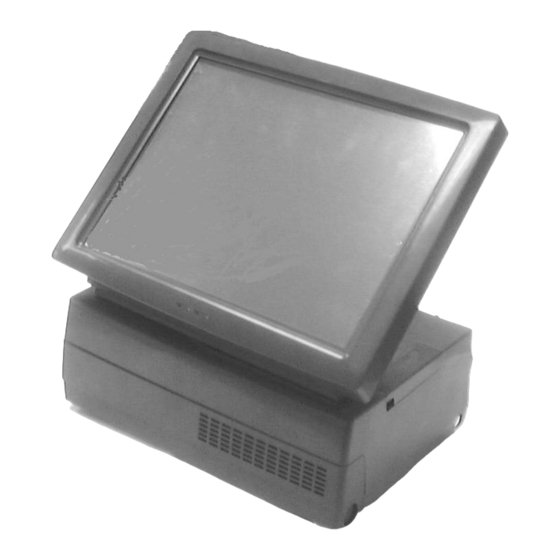
POS application to utilize the hardware of the HT-4600 & PB-4600 series which are members of the POSIFLEX integrated point-of-sale terminal product family. The HT-4600 is a compact point-of-sale system that gives the most user friendly application interface by providing a 12” touch control LCD panel and combines the performance and affordability of personal computers with the elegance and reliability of business machine. -
Page 3: Table Of Contents
CONTENTS OVERVIEW ............................5 SCOPE............................. 5 FEATURES ............................. 5 OPTIONAL ITEMS......................... 6 GENERAL SPECIFICATION ......................7 SYSTEM ............................7 POWER SOURCE........................... 8 SYSTEM POWER ON/OFF CONTROL ..................8 12VDC POWER SUPPLY INTO SYSTEM..................8 OVERALL POWER OUTPUT LIMIT.................... 9 INPUT / OUTPUT PORTS......................9 TOUCH PANEL (F HT-4600 O ) .................. - Page 4 PA-4200 ADAPTOR BOARD....................15 PRINTER: ..........................15 RELIABILITY INFORMATION ....................18 SYSTEM DEFINITIONS ........................ 19 BLOCK DIAGRAM ........................19 12 V DC IN CONNECTOR ......................20 LAN PORT ............................ 20 VGA CONNECTOR........................21 SERIAL PORT COM1/4 ....................... 21 SERIAL PORT COM2/3 ....................... 22 PARALLEL PORT LPT1 ......................
- Page 5 LAN WAKE UP ......................... 32 FINGERPRINT SENSOR ......................32 SMART CARD READER ......................33 POSIFLEX TOOLS ........................33 POSIFLEX POWER SWITCH MANAGER ................33 POSIFLEX MSR MANAGER ....................34 PROGRAMMABLE KEYPAD....................37 POSIFLEX USB TOUCH MANAGER ..................39 HARDWARE DETAILS........................42 MAIN BOARD (HT-4600)......................
- Page 6 DISCONNECT ALL CABLES ....................51 SIDE MOUNT UPGRADE KIT ....................51 SEPARATE LCD PANEL ASSEMBLY..................51 INSIDE LCD PANEL ASSEMBLY .................... 52 REINSTALL LCD PANEL ASSEMBLY..................54 OPEN THE MAIN UNIT......................55 POLE MOUNT UPGRADE KIT ....................55 DISPLAY (LM-2010) ......................56 HDD BRACKET AND RAID CARD ..................
-
Page 7: Overview
PC application software and development tools that are now inexpensively available and abundant. For the HT-4600 series terminal is powered by most up to date CPU and provides a color TFT LCD screen with a resistive type touch control panel on sturdy and easily adjustable structure on top of the main unit. -
Page 8: Optional Items
+12V power on COM2/3 by jumper setting. The COM2/3 is default as no power at delivery. Parallel Port: Each HT/PB-4600 system is equipped with a parallel port that supports SPP/EPP/ECP. VGA Port: There is a VGA connector for connection of external monitor with + 12 V DC power supply included. -
Page 9: General Specification
g) Optional COM 5/6 for additional peripherals. h) SSD HDD SATA HDD with RAID control board. GENERAL SPECIFICATION SYSTEM CPU: Supported CPU as following table. Clock Celeron 575 2.0GHz, T3100 (Duo code) 1.9GHz, P8400 (Core 2 Duo) 2.26GHz, T9400 (Core 2 Duo) 2.53GHz, RAM: DIMM socket * 2 ,DDR-2 667/800MHz ,Max 4GB 2.5”... -
Page 10: Power Source
POWER SOURCE DC power adaptor: Item Specification Voltage range of power input 100 ~ 240 V AC Load limit of power input 2.5 A max. Input frequency 47 / 63 Hz Output voltage 12 V DC Output current 6.6 A max. System: Total Power Consumption... -
Page 11: Overall Power Output Limit
OVERALL POWER OUTPUT LIMIT Including COM 2/3 ports: + 5 V DC / 1 Amp max or +12V DC/ 1 Amp All normal USB: 5 V DC / 500 mA each port. VGA: +12 V DC/1 A INPUT / OUTPUT PORTS 1 x mini DIN 6 pin female PS/2 KB jack 1 x mini DIN 6 pin female PS/2 mouse connector 1 x VGA display port for external monitor (for HT&PB-4600 ) or... -
Page 12: Preload Os
PRELOAD OS Option among Win XP, WEPOS and POSReady. OPERATOR DISPLAY (HT-4600 only) Display Type COLOR TFT 12.1” LCD View area 246 mm x 184 mm (9.7” x 7.3”) Internal interface LVDS Control knob Brightness Resolution 1024 X 768 Memory size Support DVMT 5.0 Tilt angle 15°... -
Page 13: Environmental
LCD @ 50°: 295 mm (W) x 258 mm (D) x 289 mm (H) or 11.6” x 10.2” x 11.4” PACKING: 408 mm (W) x 338 mm (D) x 375 mm (H) or 16.1” x 13.3” x 14.8” PB-4600 DIMENSIONS: SYSTEM: 279 mm (W) x 243 mm (D) x 114 mm (H) or 11.0”... -
Page 14: Compliance Approvals
COMPLIANCE APPROVALS Whole system meet CE, FCC class A standard (Meet IEC61000-4-2/-3/-4/-5/-6/-8/-11) Power supply is UL, VDE approved RoHS OPTIONS SECOND DISPLAY ON BASE MODEL Number LM2010 Display Type Color TFT 10.4" View Area (mm) 211.2 x 158.4 Interface Internal Interface 1 channel LVDS Luminance 230 cd/m... -
Page 15: Dram Expansion
Character format 5 X 7 8 x 16 or 16 x 16 Character code pages International character sets Command modes Green w/ Dark blue / White / Blue Display color Blue or Green Yellow green background filter background Contrast adjust N. -
Page 16: Side Mount Upgrade Kit Sd300
20 programmable single keys of size 19 x 19 mm MAGNETIC STRIPE READER: Reader head options: ISO 2 tracks (track 1 + track 2); ISO 3 tracks (track 1 + track 2 + track 3) Characteristic parameters of ISO readers can be set via software AAMVA/CA DMV format supported in ISO 3 tracks model SMART CARD READER: PC/SC 1.0 standard, EMV level I... -
Page 17: Nd Hdd With Raid Control Board
HDD WITH RAID CONTROL BOARD 2.5” SATA HDD. SATA HDD RAID CONTROL CARD(FT607A) SSD HDD 2.5” SATA interface SSD can’t coexist with HDD in main unit PA-4200 ADAPTOR BOARD +24V power supply for printer. PCI interface. PRINTER: PP-2000 1. 2-station receipt/journal/validation printer 2. - Page 18 9. Built-in character registration function with 256 KB flash memory for downloading and storing special character pattern or graphics for store logo 10. Supports option either alarm type or buzzer type kitchen alarm PP-5600 1. Dot matrix impact 9 pin 2.
- Page 19 8. Default with serial interface, option for parallel, USB, WI-FI or LAN interface by plug in module. PP-8000 1. Supports UPOS 1.8 2. WEPOS compliant 3. High speed thermal line printer up to 220 mm/sec 4. High resolution 8 dots/mm by 512 dots/line (576 dots max.) 5.
-
Page 20: Reliability Information
RELIABILITY INFORMATION TOUCH PANEL LIFE EXPECTANCY (TOUCHES AT SAME SPOT): RESISTIVE TYPE: 35,000,000 UP MSR LIFE EXPECTANCY: 500,000 PASSES WHOLE SYSTEM MTBF: 50,000 Hrs at 90% confidence level. -
Page 21: System Definitions
SYSTEM DEFINITIONS BLOCK DIAGRAM PS/2 PS/2 Touch Panel Mouse Port Mouse Touch Signal Controller LCD & Touch Connector LCD Panel PS/2 KB PS/2 LM-2010 Port (+12V) Port screen for HT series) 12 V DC PSU Circuit DDR2 667/800 Adaptor DIMM Intel Celeron 575 1/3/5 Devices... -
Page 22: 12 V Dc In Connector
12 V DC IN CONNECTOR PIN ASSIGNMENT OF 4 PIN PLUG: PIN # DEFINITION +12 V +12 V CASE CASE CHASSIS GND LAN PORT PIN ASSIGNMENT OF 8 PIN TELEPHONE JACK: PIN # DEFINITION PIN 1 TD1 + TD1 - TD2 + TD2 - TD3 +... -
Page 23: Vga Connector
VGA CONNECTOR This port is a standard 3 x 5 D-sub VGA connector PIN # DEFINITION PIN # DEFINITION PIN # DEFINITION NCID0 GREEN DDC_DATAID1 BLUE HSYNC NCID2 NC/+12VKEY VSYNC DDC_CLKID3 SERIAL PORT COM1/4 PIN ASSIGNMENT OF 9 PIN D SUB MALE CONNECTOR: PIN # DEFINITION ALTERNATIVE DEFAULT SETTING BATTWK... -
Page 24: Serial Port Com2/3
Please remember that if there is no need for power supply in these I/O ports, please disable these functions. PIN 1 CAUTION: VGA port +12V is dedicate for Posiflex 2 monitors implementation only. It must disable this power when this VGA port connect to other monitor, otherwise the monitor will burn out. -
Page 25: Parallel Port Lpt1
PARALLEL PORT LPT1 PIN ASSIGNMENT OF 25 PIN D SUB FEMALE CONNECTOR: PIN # SPP MODE EPP MODE ECP MODE - STROBE -WRITE -STROBE - ACK INTR -ACK BUSY -WAIT BUSY, PeriphAck Perror, -AckReverse SLCT SLCT - AUTO FEED -Datastb -AutoFeed, HostAck - ERROR -Fault, -PeriphRequest... -
Page 26: Ps/2 Keyboard Connector
PS/2 KEYBOARD CONNECTOR PIN ASSIGNMENT OF 6 PIN MINI-DIN FEMALE CONNECTOR: PIN # DEFINITION KBDAT KBCLK PS/2 MOUSE PIN ASSIGNMENT OF 6 PIN MINI DIN JACK: PIN # DEFINITION PMDAT PMCLK USB0 / USB1 / USB2 / USB3 / USB4 / USB5 PIN ASSIGNMENT OF EACH 4 PIN JACK: PIN #... -
Page 27: Cash Drawer Connecter
CASH DRAWER CONNECTER PIN ASSIGNMENT OF EACH 6 PIN RJ11 TYPE MODULAR JACK: PIN # DEFINITION DRAWER KICK 1 PIN 1 DRAWER OPEN SENSE +POWER DRAWER KICK 2 DRAWER OPEN RETURN AUDIO OUT PIN ASSIGNMENT OF 3.5 Ø STEREO JACK: CONTACT ON PLUG: DEFINITION: RING... -
Page 28: Application Guides
APPLICATION GUIDES POWER SUPPLY TO I/O PORTS For the power supply of serial and VGA ports, it can be setup through BIOS setting. Once switch on the terminal, press “Del” key to enter BIOS. Please select “Integrated Peripherals” in the main menu as well as choose “SB GPIO Control”. Afterward, there are COM 2/3 DB9 +5V and VGA +12V set up function can be select. -
Page 29: Ps/2 Interface Device
Win 2000. The registry modification as hot fix mentioned in web site http://support.microsoft.com/default.aspx?scid=kb;en-us;262798 does not work in this series. The only solutions are to connect a PS/2 keyboard or Posiflex programmable keyboard for the application or to use an USB interface device (e.g. bar code scanner) instead of the PS/2 interface one or to use other OS. -
Page 30: Customer Display
This function can also be achieved by use of the Posiflex Power Switch Terminal Manager. -
Page 31: Software Switch Off
SOFTWARE SWITCH OFF An easy method for software control to turn the system off is the software off switch. This function can be very useful in unattended application. The hexadecimal command string for software switch off function is : <06> <16> <19> <1D> <n>. In the above, the “n”... - Page 32 though very unlikely still fail. When such situation happens, please remove the external power input from the adaptor and disconnect the UPS battery for few minutes to reset the hardware registers. One example of the need for this forced power off function could happen when power switch is triggered within 10 seconds of last switching off.
-
Page 33: Automatic Power On Control
AUTOMATIC POWER ON CONTROL When the system is turned off after a successful boot up, the preset automatic power on functions if set as below will keep monitoring for the preset conditions and turn on the system when the preset conditions are met. Please note that if the system is improperly turned off before a complete boot up procedure, the above preset power on control functions will be disabled until next turning off after a complete boot up. -
Page 34: Lan Wake Up
LAN. Both machines should be using same brand of LAN chip. First the MAC address of the target machine should be checked. Please obtain the file “RSET8139.EXE” from Posiflex Product Information CD in subfolders like \Drivers\KS631X\LAN_621 and execute this file on the target machine. Select the item “View Current Configuration”... -
Page 35: Smart Card Reader
(SLE4418/28), SDA/I2C, 4403, 4433, 4404, 896 etc. It communicates with the system as USB 2.0 full speed device. POSIFLEX TOOLS In the preinstalled OS there will be a program group named “POSIFLEX Tools” for specific Posiflex device(s) installed. POSIFLEX POWER SWITCH MANAGER... -
Page 36: Posiflex Msr Manager
For systems with MSR on PS/2 interface, the “Posiflex MSR Manager” from \Drivers\KP\KBMSR\MSR_xxx shall be installed. It operates in similar way to the Posiflex USB MSR Manager. When the PS/2 MSR in KP-100 is used under DOS HT-4600/PB-4600 series Technical Manual 34... - Page 37 environment, please copy the \Drivers\KP\KBMSR\DOS\MSR.exe to the root directory and execute it to generate a “MSR.dat” file also in root directory. Please include command “MSR –s” in the autoexec.bat for proper operation. USE ALT-NUM EMULATION This function is required only for language systems using a different keyboard layout of the alphabetical part from the US keyboard when track 1 of the (USB) MSR is enabled.
-
Page 38: Msr Will Send The Leading Code
MSR WILL SEND THE LEADING CODE In data encoding of the magnetic stripes, each tracks are separated with each start/end sentinels. However the user may decide whether to send codes of/for these sentinels or not depending on the requirement of the application software. The MSR will always send a “CR”... -
Page 39: Programmable Keypad
“Posiflex Programmable Keyboard” “Posiflex Programmable Keyboard” will appear program group “Posiflex Tools” of the preloaded OS. This utility is used to define the programmable keys on KP-200 or KP-200U under Windows environment. \Drivers\KP\KBW40.xxx (for KP-200) HT-4600/PB-4600 series Technical Manual 37... -
Page 40: The Command Menu
The “Edit” menu helps the editing operation like copy, paste or clear the programmed content of a programmable key. Please ignore any gray command relating to “Page” that is applicable only to other models of Posiflex programmable keyboard and remains here only for consistency consideration. Same comment applies to the gray “View”... -
Page 41: Posiflex Usb Touch Manager
Calibrate – This button engages the “Posiflex USB Touch Calibrator”. Edge Acceleration – This function engages the “Posiflex USB Touch Edge Acceleration Tool” and helps to find the hidden taskbar or thin scroll bar through touch. -
Page 42: Usb Touch Calibrator
Hide Cursor / Show Cursor – This button hides or shows the mouse cursor on screen display. Please never hide cursor before the touch is enabled and calibrated. Buzz On – This check box together with the 2 list buttons below it determines the frequency and duration of the internal buzzer beep as response to touch on touch panel. -
Page 43: Usb Touch Edge Acceleration Tool
USB TOUCH EDGE ACCELERATION TOOL This program helps to find the hidden taskbar or thin scroll bar through touch. Enable ... – Each check box determines whether or not to engage edge acceleration against which edge of screen. Margin – This list button selects the range to engage edge acceleration toward the edge before the edge is reached. -
Page 44: Hardware Details
HARDWARE DETAILS MAIN BOARD (HT-4600) COMPONENT SIDE VGA1 Audio1 LAN1 CN3 CN4 KBMS1 COM3-4 LPT1 COM1-2 CPU_FAN1 SYS_FAN1 PCI1 CN5 CN6 CPU1 SATA1 BAT1 SDVO1 DIMM1 DIMM2 HT-4600/PB-4600 series Technical Manual 42... -
Page 45: Solder Side
SOLDER SIDE HT-4600/PB-4600 series Technical Manual 43... -
Page 46: Jumpers And Connectors
JUMPERS AND CONNECTORS ON COMPONENT SIDE Position Part Spec Usage AUDIO1 DUAL JACK Mic. in + Line out BAT1 BATSKTV Round Socket for CR2032 BUZZER Buzzer RJ11 Cash drawer connector mDIN 4 JACK 12V DC-IN 80W USB jack x3 USB Port 0, 1, 2 USB jack x3 USB Port 3, 4, 5 HDR 2x5... -
Page 47: Jumper Settings
JUMPER SETTINGS The “ ” marks in the following tables denote the factory default settings. CMOS DATA CONTROL JRTC STATUS CMOS DATA CONTROL PIN 1-2 short Clear CMOS data PIN 2-3 short Normal operation COM 2/3 +12V POWER SUPPLY JP6 STATUS COM 2/3 +12V POWER SUPPLY 1-3 Short Support COM3 DB1 = 12V... -
Page 48: Serial Adaptor Card Ht-022
SERIAL ADAPTOR CARD HT-022 COM3 JUMPERS AND CONNECTORS ON COMPONENT SIDE Position Part Spec Usage HDR 2x7 LPC Connector for CN3 in Main Board COM3 D9Mx2 COM6 Port on Top of COM5 Port HDR 2x3 +5 V DC Supply Select for COM5/6 HDR 2x3 +12 V DC Supply Select for COM5/6 JUMPER SETTINGS... -
Page 49: Lcd / Touch Control Card
Note: Please note that the 5 V or 12 V DC supply should be selected only for supporting the Posiflex serial devices that are designed to be powered from this source. Whenever such Posiflex device is to be removed from this port, the 5 V or 12 V DC supply must be deselected. -
Page 50: Solder Side (Ht-44)
SOLDER SIDE (HT-44) JUMPERS AND CONNECTORS ON COMPONENT SIDE Position Part Spec Usage Buzzer Buzzer HDR 1x2 LED Back Light Header ISP connector HDR 1x6 Firmware Update Header For Touch Panel Controller mini HDR 2x4 Touch Panel OS Support Setting LVDS1 HDR 2x10 Panel Header For 18 Bit LCD... -
Page 51: Usb Msr Control Board (Sd320)
3-4 ON ELO Touch Panel (Default) 5-6 OFF Windows/Linux/WinCE(Default) 5-6 ON MS-DOS Reserved USB MSR CONTROL BOARD (SD320) COMPONENT SIDE JUMPERS AND CONNECTORS ON COMPONENT SIDE Position Part Spec Usage SMD connector 5p To main board CN5 SMD connector 6p Reserved for next USB device SMD connector 8p... -
Page 52: Sata Hdd Raid Control Card (Ft607A)
SATA HDD RAID CONTROL CARD (FT607A) HDD SIDE SATA1 SATA2 COMPONENT SIDE CONNECTORS ON HDD SIDE Position Part Spec Usage SATA1 SATA HDD CONN To 1 SATA 2.5” HDD SATA2 SATA HDD CONN To 2 SATA 2.5” HDD ON COMPONENT SIDE Position Part Spec Usage... -
Page 53: Service And Spare Parts
SERVICE AND SPARE PARTS SERVICE GUIDE The assembly/disassembly operations for PB-4600 are almost identical to those involved for HT-4600 below with only difference in the main LCD panel and the side mounts kit being inapplicable. DISCONNECT ALL CABLES Press inward both plastic buttons at lower rear corners on both sides of the system unit (circled in right picture) to release the lower part of back cable cover. -
Page 54: Inside Lcd Panel Assembly
up from the main system unit with a ribbon cable in connection. Please find the connector removal strap from inside the bottom of the LCD assembly. Disconnect this cable by pulling at the strap. Don’t ever pull the cable itself. Then you can take the LCD assembly aside and put it in a place safe from any scratch or damage. - Page 55 The letter marks in the right picture of the inner side will be used in later descriptions. REPLACE CONTROL BOARD Remove backlight cable, LCD cable, touch cable at points A, B, C (Don’t pull at wires!) and unfasten the screws which circled in the left picture.
-
Page 56: Reinstall Lcd Panel Assembly
REBUILD LCD PANEL ASSEMBLY There are some special watch points when rebuilding the LCD panel assembly back to one piece besides reversed order of operations aforementioned. Please make sure that the 2 LED’s comes out of the 2 holes in metal frame as indicated by red arrows in the right picture when reinstalling the control board with its metal casing. -
Page 57: Open The Main Unit
arrows. Adjust the excessive cable back into the main unit through the opening in yellow dashed window on top of main unit when joining the LCD assembly with the main unit to avoid damage in application. To join the two parts, aim the red circled metal pivot to the red circled pivot hole in top plastic cover and the rest 4 blue circled metal posts to the 4 blue circled holes in top metal cover of main unit. -
Page 58: Nd Display (Lm-2010)
The whole pole mount kit can be further disassembled by pushing in the 2 locking buttons near the bottom of the pole as indicated by red arrows in left picture to separate the base unit. This operation may be required for replacement of the base unit. The upper part of the pole mount device can also be separated from the pole by first turning the display head in position as indicated in middle right picture and similarly pushing in the 2 locking buttons to release... -
Page 59: Hdd Bracket And Raid Card
HDD BRACKET AND RAID CARD After open the top cover, there is a HDD bracket can be found as left picture. To release the HDD bracket, please unplug the SATA and power cables. Afterward, please unfasten the screw which Bracket in the middle in the bracket. -
Page 60: Important! Please Read First Before Proceeding With Raid Installation
IMPORTANT! Please read first before proceeding with RAID installation When using RAID option for the first time, or when both HDD connecting to RAID board are new, RAID control board needs to be manually reset. In the scenario where a RAID upgrade kit is being installed to the system that already has the HDD, this existing HDD must get installed to the right side and then the 2 HDD should be installed to the left side. -
Page 61: Extended Pci Riser Card
EXTENDED PCI RISER CARD To apply any PCI extension riser card, please remove the red circled PCI I/O bracket screw and take out the arrowed PCI I/O bracket that is holding the arrowed PCI I/O plate in place as in the upper right pictures. -
Page 62: Nd Display Adaptor Board
DISPLAY ADAPTOR BOARD Please turn off the terminal before assemble the VGA adaptor board. Fix the VGA adaptor board to the reserved holes in I/O plate and fasten the Hex screws which circled in the lower picture. Next, please connect the cable to the VGA adaptor board and connect the other side to the mainboard. -
Page 63: Replace Mainboard
REPLACE MAINBOARD After removal of LPC adaptor card, PCI riser card, PCI I/O plate, DDR2 SDRAM, system exhaust fan and all type of connections from the main board and please use appropriate tool to release the power switch knob and power switch post (marked in following picture) from the power switch on main board through the gap between power supply and the front metal wall of chassis. -
Page 64: Spare Parts List
SPARE PARTS LIST The column “Pos.” in the list below refers basically to the ID numbers indicated in the Assembly Drawing. If this column is not available, it refers to a packaging item. The column “S.” indicates the alternative selections available for that position. This list is subject to update without notice. - Page 65 LCD Back Cover Assembly for Non Touch System, 35446005006 Ivory 15440310023 Pole Hole Cover, Black 15440310026 Pole Hole Cover, Ivory 15440305013 Cable Cover, Black 15440305016 Cable Cover, Ivory 15440307013 USB Cable Cover, Black 15440307016 USB Cable Cover, Ivory 21943008002 1" SATA Disk Moudle 8G 21943001602 1"...
- Page 66 21103200063 CPU Celeron 575 2.0G/1M Cache 21106226013 CPU Intel Core 2 Duo 2.26GHZ 21106253011 CPU Intel Core TM2 Duo 2.53G System Cooling Fan 50*50*15mm, 3 Pin/12V, 2 21837105120 Ball Bearing, 4800RPM Flat Head Self- Tapping Screw∮4.7-10L 10523047102 21863245420 Extension Cable for USB, L=220mm COM5/6 Adaptor Kit, w/ Adaptor Board &...
- Page 67 10684038082 Binding Head Screw #6/32-8L SW+W-Ni 35414005010 24V Power Kit, w/Cable & Power Adaptor, Ver.C 10245112121 Wire Clip, Black 12.1*12 for Side Mount Device 10245112122 Wire Clip, Beige 12.1*12 for Side Mount Device 21901302032 Li-Battery CR2032 21972080125 Power Adaptor, L=1800mm, 4PIN, 12V/80W Power Cord for Australia, L=1800mm, With IEC- 21868100510 C5 Connector...
-
Page 68: Assembly Drawing
ASSEMBLY DRAWING HT-4600/PB-4600 series Technical Manual 66...
Need help?
Do you have a question about the HT-4600 Series and is the answer not in the manual?
Questions and answers