Table of Contents
Advertisement
Quick Links
One Technology Way • P.O. Box 9106 • Norwood, MA 02062-9106, U.S.A. • Tel: 781.329.4700 • Fax: 781.461.3113 • www.analog.com
Evaluation Board for the
FEATURES
Full-featured evaluation board for the
On-board power supplies
Standalone capability
PC control in conjunction with system demonstration
platform (EVAL-SDP-CB1Z)
PC software for control and data analysis
EVAL-AD7091RSDZ
CONTENTS
Evaluation board hardware
Evaluation software CD for the
Mains power supply adapter
ADDITIONAL EQUIPMENT NEEDED
System demonstration platform (EVAL-SDP-CB1Z) when
using evaluation software
Signal source
ADSP-BF527
DSP
VDRIVE 3.3V
SDP BOARD
PLEASE SEE THE LAST PAGE FOR AN IMPORTANT
WARNING AND LEGAL TERMS AND CONDITIONS.
AD7091R
AD7091R
AD7091R
FUNCTIONAL BLOCK DIAGRAM
CONVST
CS
SCLK
SDO
V
LK5
A B
DGND VDRIVE
Figure 1.
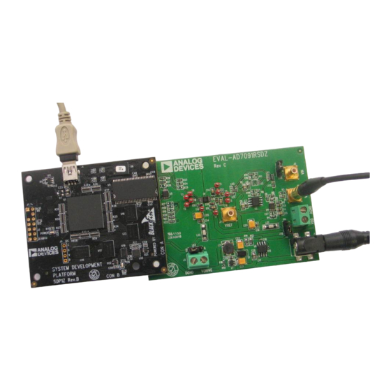
EVAL-AD7091RSDZ
Analog-to-Digital Converter
EVALUATION BOARD DESCRIPTION
The
EVAL-AD7091RSDZ
designed to allow the user to easily evaluate all features of the
AD7091R
analog-to-digital converter. The evaluation board can
be controlled via the SDP connector (J4). The SDP board allows
the evaluation board to be controlled through the USB port of a
PC using the
EVAL-AD7091RSDZ
On-board components include: the
rail-to-rail op amp, the
dual op amp, and the
dropout linear regulator.
AD7091R
V
DRIVE
DD
ON-BOARD
POWER SUPPLY
Block Diagram
Rev. 0 | Page 1 of 20
AD7091R User Guide
is a full-featured evaluation board
software.
AD8031
high speed precision
AD8032
high speed precision rail-to-rail
ADP3303
high accuracy 200 mA low
VIN
V
IN
VINB
BIAS UP
B
LK6 A
DC
JACK
UG-409
Advertisement
Table of Contents

Related Manuals for Analog Devices AD7091R


Summary of Contents for Analog Devices AD7091R
-
Page 1: Features
AD7091R User Guide UG-409 One Technology Way • P.O. Box 9106 • Norwood, MA 02062-9106, U.S.A. • Tel: 781.329.4700 • Fax: 781.461.3113 • www.analog.com Evaluation Board for the AD7091R Analog-to-Digital Converter FEATURES EVALUATION BOARD DESCRIPTION Full-featured evaluation board for the... -
Page 2: Table Of Contents
UG-409 AD7091R User Guide TABLE OF CONTENTS Evaluation Board Software ...............7 Features ....................1 Software Installation ..............7 EVAL-AD7091RSDZ Contents ............1 Launching the Software ..............8 Additional Equipment Needed ............1 Description of Main Software Window ........9 ... -
Page 3: Eval-Ad7091Rsdz Quick Start Guide
AD7091R User Guide UG-409 EVAL-AD7091RSDZ QUICK START GUIDE Follow these steps to quickly evaluate the AD7091R: Connect the power supply adapter included in the kit to Connecter J1 on the EVAL-AD7091RSDZ board. Install the EVAL-AD7091RSDZ software from the enclosed Connect the... -
Page 4: Evaluation Board Hardware
1.65 V to 5.25 V sion, while achieving 1 MSPS throughput rate. The AD7091R must be connected to the VDRIVE input to supply the... -
Page 5: Sockets/Connectors
In Position B, the analog signal is buffered via U3, a unity gain buffer. In Position C, the analog signal bypasses U2 and U3. This link is used to select the source of the analog input signal to the AD7091R. In Position A, the analog signal is sourced via the U2 op amp. -
Page 6: Eval-Ad7091Rsdz Basic Hardware Setup
An on-board unity gain amplifier from the enclosed CD. The full software installation procedure is detailed in the Evaluation Board Software section. buffers the signal to the AD7091R. This is the default configura- tion on the EVAL-AD7091RSDZ. Finally, connect the... -
Page 7: Evaluation Board Software
AD7091R User Guide UG-409 EVALUATION BOARD SOFTWARE SOFTWARE INSTALLATION EVAL-AD7091RSDZ kit includes software on a CD. Double-click the setup.exe file from the CD to run the install. The default location for the software is C:\Program Files\Analog Devices\AD7091R\ Install the evaluation software before connecting the evaluation... -
Page 8: Launching The Software
To launch the software, perform the following steps: From the Start menu, select Programs >Analog Devices > Figure 9. EVAL-SDP-CB1Z Drivers Installation—Windows Security AD7091R. The main window of the software then opens Click Install to proceed with the installation. (see Figure 13). If the EVAL-AD7091RSDZ... -
Page 9: Description Of Main Software Window
• Menu bar control buttons, drop-down boxes, and indicators. • Control buttons Mode. Selects the operating mode of the AD7091R. In Normal • Data capture display mode, the ADC is ready to acquire samples. In Sleep mode, the Menu Bar device enters power-down mode when the SAMPLE button is clicked. -
Page 10: Waveform Capture
UG-409 AD7091R User Guide FLASH LED. Causes the orange LED1A on the SDP board to flash, which can be a useful debugging tool. STOP. Stops the program. 1. USED FOR CONTROLLING THE Data Capture Display CURSOR IF PRESENT. 2. USED FOR ZOOMING IN AND OUT. -
Page 11: Ac Testing-Histogram
AD7091R User Guide UG-409 Figure 16. Histogram Capture Tab DC TESTING—HISTOGRAM AC TESTING—HISTOGRAM The histogram is more commonly used for dc testing. Similar to Figure 16 shows the histogram capture tab. This tests the ADC ac testing, this tests the ADC for the code distribution for the dc... -
Page 12: Ac Testing-Fft Capture
UG-409 AD7091R User Guide 1. INPUT SIGNAL INFORMATION. 2. FUNDAMENTAL FREQUENCY AND AMPLITUDE. 3. PERFORMANCE DATA. Figure 17. FFT Capture Tab choice. Furthermore, if using a low frequency band-pass filter AC TESTING—FFT CAPTURE when the full-scale input range is more than a few volts peak Figure 17 shows the FFT capture tab. -
Page 13: Summary Tab
AD7091R User Guide UG-409 Figure 18. Summary Tab SUMMARY TAB OPEN FILE Figure 18 shows the summary tab. The summary tab captures The software can load captured data for analysis. all the display information and provides them in one panel with Go to the File menu, and click Open (Sample Data). -
Page 14: Evaluation Board Schematics And Artwork
UG-409 AD7091R User Guide EVALUATION BOARD SCHEMATICS AND ARTWORK Figure 21. Schematic Page 1 Rev. 0 | Page 14 of 20... - Page 15 AD7091R User Guide UG-409 Figure 22. Schematic Page 2 Rev. 0 | Page 15 of 20...
- Page 16 UG-409 AD7091R User Guide Figure 23. Schematic Page 3 Rev. 0 | Page 16 of 20...
- Page 17 AD7091R User Guide UG-409 Figure 24. EVAL-AD7091RSDZ Top-Side Silkscreen Figure 25. EVAL-AD7091RSDZ Top Layer Figure 26. EVAL-AD7091RSDZ Bottom Layer Rev. 0 | Page 17 of 20...
-
Page 18: Ordering Information
UG-409 AD7091R User Guide ORDERING INFORMATION See Table 4 for a list of the evaluation boards compatible with the hardware described in this user guide. Table 4. Compatible Boards Model Description EVAL-AD7091RSDZ AD7091R evaluation board EVAL-SDP-CB1Z Evaluation controller board ADZS-BRKOUT-EX3 Signal breakout board Z = RoHS-compliant part. - Page 19 AD7091R User Guide UG-409 NOTES Rev. 0 | Page 19 of 20...
- Page 20 By using the evaluation board discussed herein (together with any tools, components documentation or support materials, the “Evaluation Board”), you are agreeing to be bound by the terms and conditions set forth below (“Agreement”) unless you have purchased the Evaluation Board, in which case the Analog Devices Standard Terms and Conditions of Sale shall govern. Do not use the Evaluation Board until you have read and agreed to the Agreement.
Need help?
Do you have a question about the AD7091R and is the answer not in the manual?
Questions and answers