Table of Contents
Advertisement
Quick Links
Advantech UNO-2173AF-A12E
Intel Atom Automation Computer
A l l t r a d e m a r k s , b r a n d n a m e s , a n d b r a n d s a p p e a r i n g h e r e i n a r e t h e p r o p e r t y o f t h e i r r e s p e c t i v e o w n e r s .
• C r i t i c a l a n d e x p e d i t e d s e r v i c e s
• I n s t o c k / R e a d y - t o - s h i p
Artisan Scientific Corporation dba Artisan Technology Group is not an affiliate, representative, or authorized distributor for any manufacturer listed herein.
Limited Availability
Used and in Excellent Condition
Buy Today!
https://www.artisantg.com/65625-1
• We b u y y o u r e x c e s s , u n d e r u t i l i z e d , a n d i d l e e q u i p me n t
• F u l l - s e r v i c e , i n d e p e n d e n t r e p a i r c e n t e r
Advertisement
Table of Contents

Related Manuals for Advantech UNO-2173A


Summary of Contents for Advantech UNO-2173A
- Page 1 Advantech UNO-2173AF-A12E Intel Atom Automation Computer Limited Availability Used and in Excellent Condition Buy Today! https://www.artisantg.com/65625-1 A l l t r a d e m a r k s , b r a n d n a m e s , a n d b r a n d s a p p e a r i n g h e r e i n a r e t h e p r o p e r t y o f t h e i r r e s p e c t i v e o w n e r s .
- Page 2 UNO-2173A/AF Intel Atom Fanless Box PC with 1 x LAN, 2 x COM, Mini-PCIe User Manual...
- Page 3 C&T is a trademark of Chips and Technologies, Inc. All other product names or trademarks are properties of their respective owners. Support For more information on this and other Advantech products, please visit our websites at: http://www.advantech.com For technical support and service, please visit our support website at: http://www.advantech.com/support/...
- Page 4 Product Warranty Advantech warrants to you, the original purchaser, that each of its prod- ucts will be free from defects in materials and workmanship for one year from the date of purchase. This warranty does not apply to any products that have been repaired or...
- Page 5 This product has passed the CE test for environmental specifications when shielded cables are used for external wiring. We recommend the use of shielded cables. This kind of cable is available from Advantech. Please contact your local supplier for ordering information.
- Page 6 Safety Instructions Read these safety instructions carefully. Keep this User Manual for later reference. Disconnect this equipment from any AC outlet before cleaning. Use a damp cloth. Do not use liquid or spray detergents for cleaning. For plug-in equipment, the power outlet socket must be located near the equipment and must be easily accessible.
- Page 7 The sound pressure level at the operator's position according to IEC 704-1:1982 is no more than 70 dB (A). DISCLAIMER: This set of instructions is given according to IEC 704-1. Advantech disclaims all responsibility for the accuracy of any statements contained herein. UNO-2173A/AF User Manual...
-
Page 8: Table Of Contents
Figure 1.2:UNO-2173AF Chassis Dimensions ....7 Accessories................ 8 Chapter 2 Hardware Functionality ........10 Introduction ..............10 Figure 2.1:Front panel of UNO-2173A/AF ....10 Figure 2.2:Rear panel of UNO-2173AF ....... 10 RS-232 Interface (COM1~COM2) ......... 10 RS-422/485 Interface (UNO-2173AF)......11 2.3.1 RS-422/485 Selection ........... - Page 9 Appendix A System Settings and Pin Assignments ..24 System I/O Address and Interrupt Assignment..24 Table A.1: UNO-2173A/AF System I/O Ports..... 24 Board Connectors and Jumpers........26 Figure A.1: Connector & Jumper Locations (front) ..26 RS-232 Standard Serial Port (COM1~COM2) ....27 RS-422/485 Serial Port (UNO-2173AF)......
- Page 10 Overview This chapter provides an overview of UNO-2173A/AF’s specifications. Sections include: • Introduction • Hardware specification • Safety precautions • Chassis dimensions...
-
Page 11: Chapter 1 Overview
UNO-2173A/AF has been certified by Energy Star., recognizing its extreme low power consumption and high energy utilization. To build a low-carbon society everyone needs to do thier best. By selecting the UNO-2173A/AF for your project, you have made a good contribution for this planet. UNO-2173A/AF User Manual... -
Page 12: Hardware Specifications
1.2 Hardware Specifications General • Certifications Energy Star, CE, FCC class A, UL, CCC • Dimensions (W x D x H)255 x 152 x 59 mm (10" x 6.0" x 2.3") • Enclosure Aluminum +SECC • Mounting Wallmount, DIN-rail, VESA •... - Page 13 • Serial Ports 1 x RS-422/485 serial port • Serial Port Speed 50 ~ 115.2 kbps Reserved Functions • Battery Backup SRAM* 1MB • Printer Port* 1 x printer port pin head *Note: This function is reserved for projects UNO-2173A/AF User Manual...
-
Page 14: Safety Precautions
Only experienced electronics personnel should open the chassis. Caution! Always ground yourself to remove any static electric charge before touching UNO-2173A/AF. Modern electronic devices are very sensitive to static electric charges. Use a grounding wrist strap at all times. Place all electronic compo- nents on a static-dissipative surface or in a static- shielded bag. -
Page 15: Chassis Dimensions
1.4 Chassis Dimensions 254.80 254.80 241.80 241.80 141.60 141.60 111.09 111.09 149.24 149.24 Ø4.00 4.00 Ø5.40 5.40 10.51 10.51 228.20 228.20 58.71 58.71 2.00 2.00 Figure 1.1: UNO-2173A Chassis Dimensions UNO-2173A/AF User Manual... - Page 16 254.80 254.80 241.80 241.80 141.60 141.60 111.09 111.09 149.24 149.24 Ø4.00 4.00 Ø5.40 5.40 10.51 10.51 228.20 228.20 58.71 58.71 2.00 2.00 Figure 1.2: UNO-2173AF Chassis Dimensions Chapter 1...
-
Page 17: Accessories
1.5 Accessories Please refer below for the accessory list: • 3-pin connector for power wiring (Advantech P/N : 1652003206) • 5-pin connector for COM3 RS-422/485 ( UNO-2173AF only, Advantech P/N : 1652000177) • SATA signal cable (Advantech P/N : 1700006812) •... - Page 18 Hardware Functionality This chapter shows how to setup the UNO-2173A/AF’s hardware functions, including connecting peripherals, set- ting switches and indicators. Sections include: • Peripherals • RS-232 Interface • RS-422/485 Interface • LAN / Ethernet Connector • Power Connector • PS/2 Mouse and Keyboard Connector •...
-
Page 19: Chapter 2 Hardware Functionality
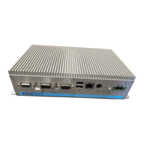
Chapter 2 Hardware Functionality 2.1 Introduction The following two figures show the connectors on UNO-2173A/AF. The following sections give you detailed information about function of each peripheral. Figure 2.1: Front panel of UNO-2173A/AF Figure 2.2: Rear panel of UNO-2173AF 2.2 RS-232 Interface (COM1~COM2) The UNO-2173A/AF offers two standard RS-232 serial communication interface ports: COM1 and COM2. -
Page 20: Rs-422/485 Interface (Uno-2173Af)
2.3 RS-422/485 Interface (UNO-2173AF) The UNO-2173AF offers one RS-422/485 serial communication interface ports: COM3. Please refer to Appendix A.4 for their pin assignments. The default setting of COM3 is RS-422. 2.3.1 RS-422/485 Selection The mode of UNO-2173AF COM3 can be selected in the BIOS. Please enter the BIOS setting screen and select the "Integrated Peripherals", then the follow screen would be shown. -
Page 21: Termination Resistor (Sw3)
2.6 PS/2 Keyboard and Mouse Connector The UNO-2173A/AF provides a PS/2 keyboard and mouse connector. A 6-pin mini-DIN connector is located on the rear panel. The UNO-2173A/ AF comes with an adapter to convert from the 6-pin mini-DIN connector to two 6-pin mini-DIN connectors for PS/2 keyboard and PS/2 mouse connection. -
Page 22: Usb Connector
Please contact Advantech if this is function is required in your project. There is a BTRY LED in the front panel of the UNO-2173A/AF, please replace the lithium battery with a new one if the BTRY LED is activated. -
Page 23: Lithium Battery Specification
BH2 is for SRAM and BH1 is for Real Time Clock 2.10 Power Button / Power Management Press the "PWR" button to power on or power off UNO-2173A/AF (ATX type). UNO-2173A/AF supports the ACPI (Advanced Configuration and Power Interface). Besides power on/off, it support multiple suspend modes, such as Power on Suspend (S1), Suspend to RAM (S3), Suspend to Disk (S4). -
Page 24: Reset Button
2.13 PCI Express Mini Card Socket UNO-2173A/AF supports one socket for PCI Express mini Card. This interface is mainly target on the wireless application such as WLAN and GPRS. User can install the card easily by the optional kit, please refer to Chapter 3.2 for the details. - Page 25 UNO-2173A/AF User Manual...
- Page 26 Initial Setup This chapter introduces how to initial- ize the UNO-2173A/AF. Sections include: • Inserting a CompactFlash Card • Chassis Grounding • Conneting Power • Connecting a Hard Disk • BIOS Setup and System Assignments...
-
Page 27: Chapter 3 Initial Setup
"Integrated Peripherals > IDE Device Setup > IDE Configuration > Enhanced Mode" 3.2 Chassis Grounding UNO-2173A/AF provides good EMI protection and a stable grounding base. There is an easy-to-connect chassis grounding point for you to use. Figure 3.1: Chassis Grounding Connection... -
Page 28: Connecting Power
3.3 Connecting Power Connect the UNO-2173A/AF to a 9~36 VDC power source. The power source can either be from a power adapter or an in-house power source. 3.4 Installing a Hard Disk The procedure for installing a hard disk into the UNO-2173A/AF is below. -
Page 29: Installing A Wireless Lan Card And Antenna
3.5 Installing a Wireless LAN Card and Antenna Please contact Advantech to prepare the following optional kit: Rear Panel for Antenna. • 1960032715N040 for UNO-2173A • 1960032715N020 for UNO-2173AF • The internal cable : 1700001854 (11cm) Wireless Module ( PCI Express mini card ) •... - Page 30 Antenna • Please select the necessary specification according to your application. • One of the suggested antenna is 1750003222 (18 cm) which is a veri- fied 802.11b/g 5dBi Dipole Antenna Then follow the below steps for the installation: Unscrew the bottom panel and open it. Install the internal cable 1700001854 on the prepared rear panel with the hole of antenna (1960032715N040 or 1960032715N020).
-
Page 31: Bios Setup
Press "DEL" in the boot-up screen to enter the BIOS setup utility. Please follow the instruction on the screen to do the necessary settings. Please note that you can try to “Load Optimized Defaults” from the BIOS Setup manual if the UNO-2173A/AF does not work properly. UNO-2173A/AF User Manual... - Page 32 System Settings and Pin Assignments...
-
Page 33: Appendix A System Settings And Pin Assignments
Appendix A System Settings and Pin Assignments A.1 System I/O Address and Interrupt Assignment Table A.1: UNO-2173A/AF System I/O Ports Address Range Device 000-01F DMA controller (slave) 020-03F Interrupt controller 1, (master) 040-05F 8254 timer/counter 060-06F 8042 (keyboard controller) 070-07F... - Page 34 Table A.2: UNO-2173A/AF Interrupt Assignment Interrupt No. Interrupt Source Parity error detected IRQ 0 Interval timer IRQ 1 Keyboard IRQ 2 Interrupt from controller 2 (cascade) IRQ 3 COM2 IRQ 4 COM1 IRQ 6 Diskette controller (FDC) IRQ 7 Parallel port 1 (print port)
-
Page 35: Board Connectors And Jumpers
A.2 Board Connectors and Jumpers There are several connectors and jumpers on the UNO-2173A/AF board. The following sections tell you how to configure the UNO-2173A/AF hardware setting. Figure A-1 shows the locations of UNO-2173A/AF’s connectors and jumpers. Figure A.1: Connector & Jumper Locations (front) Table A.3: UNO-2173A/AF Connectors and Jumpers... -
Page 36: Rs-232 Standard Serial Port (Com1~Com2)
A.3 RS-232 Standard Serial Port (COM1~COM2) Table A.4: RS-232 standard serial port pin assignments RS-232 Signal Name Appendix A... -
Page 37: Rs-422/485 Serial Port (Uno-2173Af)
A.4 RS-422/485 Serial Port (UNO-2173AF) Table A.5: RS-422/485 serial port pin assignments RS-422 RS-485 Data+ Data- A.5 Power Connector (PWR) Table A.6: Power connector pin assignments V+ (9~36V Field Ground UNO-2173A/AF User Manual... -
Page 38: Ps/2 Keyboard And Mouse Connector
A.6 PS/2 Keyboard and Mouse Connector Table A.7: Keyboard and Mouse connector pin assignments Signal Name KB DATA MS DATA KB Clock MS Clock A.7 USB Connector Table A.8: USB connector pin assignments Signal Name Cable Color DATA+ White DATA- Green Black Appendix A... -
Page 39: Vga Display Connector
A.8 VGA Display Connector Table A.9: VGA adaptor cable pin assignment Signal Name Green Blue H-SYNC V-SYNC UNO-2173A/AF User Manual... -
Page 40: Lvds And Lvds_Pwr (Uno-2173Af)
A.9 LVDS and LVDS_PWR (UNO-2173AF) A.9.1 LVDS Table A.10: LVDS pin definitions Signal Signal LVDS1_Z_CLK+ LVDS1_Z_CLK- LVDS0_Z_D0- LVDS0_Z_D0+ LVDS0_Z_D1- LVDS0_Z_D1+ LVDS0_Z_D2- LVDS0_Z_D2+ LVDS0_Z_CLK- LVDS0_Z_CLK+ VDD_DSUB VDD_DSUB LVDS1_Z_D0- LVDS1_Z_D0+ LVDS1_Z_D1- LVDS1_Z_D1+ LVDS1_Z_D2- LVDS1_Z_D2+ Appendix A... -
Page 41: Lvds Power Setting (Cn17)
VDD_DSUB (Pin 7 and Pin 20) of LVDS pin is +5V VDD_DSUB (Pin 7 and Pin 20) of LVDS pin is +3.3V A.9.3 LVDS_PWR (Backlight Control) Table A.12: LVDS_PWR pin definition Signal +12V (1.2A) INVERTER ENABLE BRIGHTNESS (PWM) +5V (1A) LVDS_DDC_CLK LVDS_DDC_DATE UNO-2173A/AF User Manual... -
Page 42: Clear Cmos (Cn3)
A.10 Clear CMOS (CN3) This jumper is used to erase CMOS data and reset system BIOS informa- tion. Follow the procedures below to clear the CMOS. 1. Turn off the system. 2. Close jumper CN3 (1-2) to clear CMOS . 3, Remove jumper CN3(1-2) 3. - Page 43 UNO-2173A/AF User Manual...
Need help?
Do you have a question about the UNO-2173A and is the answer not in the manual?
Questions and answers