
Related Manuals for Universal Devices ISY-99i Series


Summary of Contents for Universal Devices ISY-99i Series
- Page 1 ISY-99i & 994i Series User Guide April 27, 2013 (Supporting Firmware Release 3.3.10 and above)
-
Page 2: Table Of Contents
Table of Contents 1 Introduction..........................1 1.1 What's Included ........................1 1.2 Requirements ........................1 1.3 Getting To Know Your ISY ....................... 2 2 Installation ..........................5 2.1 Hardware Installation ......................5 2.2 Connecting to the ISY from a Local PC ..................5 2.3 The HTML Interface ....................... - Page 3 Appendix G: Sample ISY Programs....................83 Appendix H: Troubleshooting INSTEON Communication Issues ............ 85 Table of Figures Figure 1 ISY-99i Series Rear Panel ......................2 Figure 2 ISY-994i Series Rear Panel ......................3 Figure 3 Login Window ........................7 - ii -...
- Page 4 Figure 4 Help/About Menu ........................7 Figure 5 My URL ..........................7 Figure 6 ISY’s HTML Interface ....................... 9 Figure 7 Admin Console/File Menu ..................... 12 Figure 8 Setting the Clock ........................13 Figure 9 Change Theme Menu ......................14 Figure 10 Theme Samples .........................
- Page 5 Figure 54 Set a Variable’s Initial Value ....................44 Figure 55 Email Based on Motion Sensor Trigger ..................44 Figure 56 Email Recipients Screen ....................... 48 Figure 57 Motion Sensor Email ......................49 Figure 58 Scheduling an Email ......................49 Figure 59 ELK Configuration Screen .....................
-
Page 6: Introduction
1 Introduction Thank you for purchasing an ISY-99i / 994i Series device – Universal Devices, Inc.’s line of intelligent, stand-alone, web-enabled INSTEON controllers. With the ISY-99i / 994i Series, you can: Program, configure and manage your INSTEON devices Automate your home using sophisticated timers, triggers, and macros Conserve energy in your home Remotely control your home using the ISY’s web interface... -
Page 7: Getting To Know Your Isy
DHCP server using an Ethernet cross-over cable (not included), the following are required in order to configure the ISY's network parameters: For the ISY-99i series device you will need a null-modem serial cable and available serial port (or USB to serial adapter) on your computer. -
Page 8: Figure 2 Isy-994I Series Rear Panel
(included) to connect between your ISY and the PLM. WARNING: DO NOT use this port to connect to an Ethernet router or switch. Port B (ISY-99i Series ONLY) is a 9-pin female RS-232 serial port used for initial configuration for users without a DHCP-enabled network, or for advanced troubleshooting. - Page 9 NOTE: Your ISY may also include an externally accessible SD card slot. Please DO NOT remove the SD card while the ISY is running. ISY’s without an external SD slot must be opened in order to replace the SD card. For instructions on replacing your SD card, please see Appendix C: Replacing / Upgrading Your SD Card.
-
Page 10: Installation
2 Installation Installation of the ISY is completed in several easy steps. The following instructions assume that you are installing the ISY on a DHCP-enabled network (true in the vast majority of cases) and are using a Windows-based PC to connect to the ISY. If you do not have a router or other DHCP-enabled network to plug the ISY into and plan on using a direct connection to a PC, or if you are using an OS other than Windows, please see our online Wiki for more advanced installation instructions:... - Page 11 Web Browser: Please be sure your PC is running a Java-enabled web browser, such as Internet Explorer or FireFox. As shipped from the factory, the ISY is configured to obtain an IP address via DHCP. There are a few easy ways to connect to your ISY and find its local URL: Option1 (ISY-994i Series ONLY): In most cases, the quickest and easiest way to connect to the ISY for the first time on a Windows PC is to open a web browser and type in the following URL:...
-
Page 12: Figure 3 Login Window
Once you launch the Administrative Console, you will be presented with a login window asking you to authenticate to your ISY. The default login information is: Username: admin Password: admin Figure 3 Login Window To find your ISY’s login URL, click the HELP -> ABOUT pull down menu: Figure 4 Help/About Menu Then look for the address listed after “My URL.”... -
Page 13: The Html Interface
When using DHCP, in some cases your ISY may receive a new IP address from your router (or other DHCP server). If this happens, you may not be able to use the old address to connect to your ISY. To find out your ISY’s new address, simply double-click your My Lighting icon or visit the following URL to automatically find the ISY (and its new address) on your network: http://isy.universal-devices.com/99i... -
Page 14: Figure 6 Isy's Html Interface
Figure 6 ISY’s HTML Interface You won’t be able to do much until you start configuring your ISY, but here is a summary of what you can do with the HTML Interface: The Home Tab: My Devices & Scenes – This is where you will find a list of all INSTEON devices and scenes you have on your ISY. - Page 15 My Programs – By clicking this link you can view the status of any Programs you have stored on your ISY and also control them. You will learn more about Programs in the section titled 3.3 The Programs \ Details Tab. Networking Resources –...
-
Page 16: Launching The Administrative Console
Install Admin Console – This button installs a local copy of the Admin Console applet to your system, creating a desktop icon so you can launch the Admin Console quickly and easily. Finally, the Admin Console tab launches the ISY’s Administrative Console, which does require Java. -
Page 17: The Administrative Console
3 The Administrative Console The Administrative Console is divided into several tabs, each used to configure different aspects of your ISY. 3.1 Basic Configuration Before getting started, it’s important to configure a few basic things on the ISY. 3.1.1 Setting the User ID and Password For security reasons, please change the default username and password used to connect to your ISY. -
Page 18: Keyboard Navigation
Figure 8 Setting the Clock Please be sure to check the Daylight Saving option if applicable in your area. Also feel free to check and configure the NTP Server option if your ISY is able to access the internet. The ISY will periodically sync its clock with the specified NTP server to ensure accurate time. -
Page 19: Themes
3.1.4 Themes You can choose between several different predefined color schemes to suit your preference. To select a different theme click the File pull-down menu, then Themes, then Theme Colors and choose your scheme. Please note that the Administrative Console must be closed and re-opened for your theme change to take effect. -
Page 20: The Main Tab
3.2 The Main Tab The Main tab is where you can add, configure, and manage your INSTEON devices. Figure 11 The Main Tab The left-hand pane displays a hierarchy of folders, devices, and scenes contained within your ISY. The right-hand pane displays detailed information on what you have selected on the left. -
Page 21: Figure 12 The Link Management Menu
Figure 12 The Link Management Menu Start Linking. The majority of INSTEON devices can be added using this method. Once this option is selected, simply go to each INSTEON device installed and hold the SET button for 3-5 seconds. The ISY will then see each device, and add it to the device list. As you hold the SET button on each device, you will see the device added to the left-hand pane. - Page 22 Remove Existing Links. This option will add the device to the ISY, and also remove any existing links in the device. This is the default and the best option to choose if you would like a clean start, or if it is a brand new device. Add Devices Found in Links and Remove Existing Links.
-
Page 23: Adjusting Settings On Insteon Devices
Figure 14 New INSTEON/A10/X10 Screen 3.2.2 Adjusting Settings on INSTEON Devices Some INSTEON devices have settings that can be changed through the ISY. For example, dimmable devices have On Levels and Ramp Rates that can be adjusted. On Levels are the brightness levels at which a device is turned on when pressed (25%, 75%, etc.). -
Page 24: Figure 15 File/Automatic Writes Menu
To toggle this option, click the FILE menu: Figure 15 File/Automatic Writes Menu Automatic Writes to Devices (PRO Series ONLY). When this option is on, changes are written automatically to devices. Toggle this option off to disable automatic writes. When toggled back on, all pending changes will be sent to devices. -
Page 25: Creating Insteon Scenes
To write all pending changes for a single device (without turning Automatic Writes back on), simply right-click the device and choose Write Updates to Device: Figure 17 Write Updates to Device 3.2.3 Creating INSTEON Scenes Scenes are collections of INSTEON devices that react to and with one another in various ways. -
Page 26: Figure 18 New Scene Screen
To create a Scene, simply click the New Scene option under the Link Management pull- down menu, or click the New Scene button on the ISY’s toolbar. Figure 18 New Scene Screen Name the Scene accordingly, click OK, and your scene will appear in the left-hand pane. To add devices to a scene, simply right-click a device, choose Add To Scene, and choose the appropriate Scene. -
Page 27: Figure 20 Cross-Linking
One example of a scene might be a group of 2 devices that control the same light – typically called a “virtual 3-way circuit”. For example, you might have 2 switches in your kitchen that you’d like to control your kitchen table light. One switch is physically attached to the kitchen table light, but you’d like the other switch to control it as well. -
Page 28: Organizing Insteon Devices And Scenes
To set values when the ISY itself is the controller (for example when controlled through the Administrative Console or through ISY Programs), click the scene itself on the left-hand pane. In the example below, when the highlighted controller is pressed the TheaterControls1A- Table device will turn on to 60% and the TheaterMain1 and TheaterMain2 devices will turn off. -
Page 29: Controlling Insteon Devices And Scenes
more identifiable. You can also rename by left-clicking to highlight, then hitting the F2 key. A dialog box will pop up giving you several rename options if you’d like to rename associated devices as well. Folders. Feel free to create folders to help organize your Devices and Scenes. Folders can be created by either right-clicking on the Network node (located on the left-hand pane) and choosing New Folder, or using the New Folder icon located on the Administrative Console’s top toolbar. -
Page 30: The Programs \ Details Tab
Fast Off. Clicking the FAST OFF button turns the INSTEON device or scene off instantly (ignoring its programmed Ramp Rate). Brighten. Pressing and holding the BRIGHTEN button starts ramping up the brightness level of a dimmable INSTEON device. Release the button to stop the ramp up. Dim. -
Page 31: The Basics Of Isy Programs
using timers, triggers, macros, etc. Programs also allow you to utilize the ISY’s optional IR receiver, optional modules, and more. To open this tab, first click the Programs tab, then click the Details sub-tab. The Programs \ Details screen is divided into several sections. The left-pane is used to show your program hierarchy. -
Page 32: Figure 25 Naming A Program
The ISY will prompt you to name your program – type in something descriptive so you will be able to easily identify it in the future. Figure 25 Naming a Program Once you name your program click the IF statement to set your conditions. Figure 26 IF Statement VJK: Redo screen shot. -
Page 33: Figure 28 Adding To The If Statement
Figure 28 Adding to the IF Statement Next, click on the THEN statement to highlight it. The THEN portion of a program runs once the IF portion of a program is true. At the bottom of the screen choose the device or scene that you want to turn on at sunset. -
Page 34: Figure 31 Highlight "Time Is Sunset
But, let’s say we wanted something slightly more sophisticated. Say we want to turn the lights on 30 minutes AFTER sunset, and turn them off at 10pm. To do that, we’ll make a couple of quick adjustments to the program. First we’ll click the “Time is Sunset”... -
Page 35: Building Your Programs
Figure 33 Adding an ELSE Statement Click ADD TO ELSE and your final program should look like this: Figure 34 Adding to the THEN Statement Hit the SAVE CHANGES button in the bottom left, and your new program is complete! NOTE: Always remember to hit the Save Changes button when finished creating or editing your programs! Changes are not saved to the ISY until this button is pressed. -
Page 36: Figure 35 Additional Program Buttons
When working with Programs containing multiple lines, additional buttons will appear to help arrange your lines and group them together with AND / OR parenthesis. Figure 35 Additional Program Buttons To remove a line, simply highlight it and click REMOVE LINE. To rearrange your lines, highlight them and click MOVE LINE UP or MOVE LINE DOWN. -
Page 37: Figure 37 Adding Program Comments
Figure 37 Adding Program Comments To temporarily disable a program, un-check the ENABLED box on the right-hand side of the screen and hit the SAVE CHANGES button. Or simply right-click a program and choose Disable. Figure 38 Temporarily Disable a Program Disabled programs are displayed with a red X in the Program list as shown below: Figure 39 Display of Disabled Programs Programs that have changes and need to be saved are displayed in the program list with a... -
Page 38: Program Schedules
Figure 40 Display of Unsaved Programs with Changes 3.3.4 Program Schedules In the Add To Program button section, click SCHEDULE to add a Schedule to your Program. Schedules allow you to add IF statement based on time of day, ranges of times, sunrise/set, days of the week, etc. -
Page 39: Conditions
Or a program that would run at 10pm on weekdays: Figure 42 Schedule Screen – Time & Day Once your Schedule statement is as intended, click the ADD TO IF button to add it to your program. 3.3.5 Conditions In the Add To Program button section, click CONDITION to add a Condition to your Program. -
Page 40: Figure 43 Status Condition - 100% Bright
For example, to see if your kitchen light is at 100% brightness you could do the following: Figure 43 Status Condition – 100% Bright But, to see if the same light is on at ANY brightness you might do this instead: Figure 44 Status Condition –... -
Page 41: Program Actions
Figure 45 FAST ON Condition Program conditions check to see whether or not other ISY Programs are currently True or False. X10 conditions trigger programs when X10 commands are received by the ISY. For example, to run a program if an X10 M1 ON command is received: Figure 46 X10 Condition Variable conditions trigger programs based on the value of a defined variable. - Page 42 Insteon actions send INSTEON commands to devices or scenes to turn them ON, OFF, etc. Not all options available for all devices: ON (send a standard ON command) OFF (send a standard OFF command) FAST ON (turn device full on ignoring programmed on level or ramp rate) FAST OFF (turn device full off ignoring programmed ramp rate) FADE UP (start the ramp up of a dimmable device FADE DOWN (start the ramp down of a dimmable device)
-
Page 43: Figure 47 Wait Action
Disable (disables and enabled program) Enable Run at Startup (sets a program to run at startup) Disable Run at Startup (sets a program to NOT run at startup) Wait actions create a pause in a running program. For example, to turn your driveway lights off 5 minutes after your front door lights are turned off, you could do the following: Figure 47 WAIT Action If the RANDOM checkbox is checked, a random time between 0 and the specified time is... -
Page 44: Program Folders
For example, to flash your driveway lights on and off 5 times, every 2 seconds, you could: Figure 49 Flash Lights ON and OFF Variable actions allow you to adjust the value of a defined variable within program. For more information on Variables please see the section titled Using Variables. Adjust Scene actions adjust the On Levels and Ramp Rates of devices or scenes. -
Page 45: Figure 50 Folder Conditions
Figure 50 Folder Conditions To set conditions on a folder, simply click the folder to select it and adjust conditions as you would any ISY Program. 3.3.8 Other Functions Status. To quickly view the current status of a Program, simply right-click it and choose Status which brings you to the Program Summary tab with the selected program highlighted. -
Page 46: The Programs \ Summary Tab
3.4 The Programs \ Summary Tab The Programs \ Summary page displays a list of all your Programs, Folders, and information about each. To open this tab, first click the Programs tab, then the Summary sub-tab. Here are the columns of information available: Name (the Program or Folder’s name) Enabled (shows whether the Program is currently enabled or disabled) Run At Startup (shows whether the Program is set to run at startup) -
Page 47: Variables
Run (If) – force the evaluation of the IF statement and run the program Run Then – force the run of the THEN portion of a program Run Else – force the run of the ELSE portion of a program Stop –... -
Page 48: Using The Status Of Variables In Programs
Value – This is the current value of the variable. Again, this can be defined here and also modified via arithmetic operations using ISY Programs. Last Changed – This displays the date and time that the variable was last modified. 3.5.2 Using the Status of Variables in Programs You can use the If portion of an ISY Program to check the state of a variable. -
Page 49: Using Variables In Notifications
For example, the following screenshot increases a variable by 1: Figure 53 Increment a Variable by 1 This example sets the Init value of a variable to the current value of another variable: Figure 54 Set a Variable’s Initial Value 3.5.4 Using Variables in Notifications Variables can also be useful when sending notifications. -
Page 50: The Integrated Ir Receiver
3.6 The Integrated IR Receiver If your ISY came equipped with an integrated IR receiver (model numbers that contain “/IR”), Programs can be triggered using an RC5-compatible remote control. To program IR codes into the ISY, click the Configuration tab, then the IR sub-tab. The IR configuration page lists all IR codes currently recognized by the ISY. -
Page 51: Using The Ir Learning Mode
40 codes labeled “IR_001, IR_002, etc.” This will overwrite any IR codes you may already have stored on your ISY. With Logitech Harmony remote controls, you can simply choose the Universal Devices ISY from the Harmony software’s built-in database. The Harmony software will allow you to drag and drop the ISY’s 40 default IR codes onto buttons on your remote control. -
Page 52: Notifications
We highly recommend testing an IR code well to ensure it is 100% reliable with the ISY before saving. Make sure the ISY consistently displays the code correctly when the button is Pressed, Held, Released, etc. When done teaching IR codes to your ISY, hit the “Leave Learning Mode” button on the top of the screen and be sure to “Save”... -
Page 53: Custom Notifications
Figure 56 Email Recipients Screen Choose the type of recipient you’d like to add (Regular Email, text notification, etc.), hit the Add button, then type the recipients corresponding address as instructed. When done, hit OK to finish editing the group. Always remember to hit the Save button on the bottom of the Admin Console to save your settings to the ISY. -
Page 54: Figure 57 Motion Sensor Email
Use the drop-down boxes to add real time information to your notification, such as current time/date, variable values, security system information, weather conditions, etc. Once created, these custom notifications can be triggered and sent using your ISY Programs. Note that Custom Notifications supports plain text, HTML and XML. For example, you could set up a variable used to count how many times your motion sensor triggered every night. -
Page 55: Interfacing With The Elk
Here is a link to a page on the ISY wiki that details the available Email Substitution Variables: http://wiki.universal-devices.com/index.php?title=ISY- 99i_Series_INSTEON:Custom_Email_Substitution_Variables 3.8 Interfacing with the Elk If you have an Elk M1 alarm/automation panel installed, it can be configured to communicate with the ISY. Once communication is established, you can: Arm/Disarm your Elk from the ISY’s web interface and Administrative Console Control Devices and Scenes stored on the ISY from your Elk (through Elk keypads, programs stored on the Elk, etc.) -
Page 56: Figure 60 Elk Status Screen
If successful, a “Security System” bar will appear on the top of your Administrative Console showing you the current state of your Elk and allowing you to type your Elk’s security code and arm/disarm it: Figure 60 ELK Status Screen To allow control of your ISY-configured Devices and Scenes from the Elk, you must export your lighting information from the Administrative Console and import this file onto your Elk using ElkRP. -
Page 57: Optional Modules
Figure 61 Import Lighting Data Follow the on-screen instructions to finish importing the ISY’s information into your Elk. Enhanced Elk-integration capabilities are available when using the optional Elk Security System module. See the section titled 3.9.5 The Elk Security System Module for more information. - Page 58 Web Server – using the Network Module, the ISY can be used as a web server to server up your own applications, pictures and files. Network Resources – with the Network Module, the ISY allows you to call any network resource (TCP, UDP, HTTP, HTTPS) using ISY Programs.
-
Page 59: Figure 62 Networking Actions
Once devices have been added, they will be available in ISY Programs as Actions under the Networking category: Figure 62 Networking Actions More information on known-compatible 3 party devices and how to control them is available in this Wiki article: http://wiki.universal-devices.com/index.php?title=ISY- 99i_Series_INSTEON:Networking:Network_Resources Wake On LAN... -
Page 60: Climate Module
3.9.2 Climate Module Using the Climate Module, you can create ISY Programs using local weather information as conditions. This module gathers information from WeatherBug, which provides a huge number of weather stations to pull data from. To view and configure your Climate Module, click the Configuration tab in the ISY’s Administrative Console then the Climate sub-tab. -
Page 61: Figure 64 Local Weather Information
You should now see local weather information as shown below: Figure 64 Local Weather Information - 56 -... -
Page 62: Electricity Module
Now that your Climate Module has been configured, you can use this information as Conditions in ISY Programs. When choosing a condition, choose Module and Climate to see all available conditions: Figure 65 Using Climate Conditions 3.9.3 Electricity Module This module is available ONLY with the ISY-994i Series. Brultech Electricity Meters can be utilized to monitor electricity consumption. -
Page 63: Open Auto Demand / Response Module
Once your Brultech meter is configured, you can use this information as Conditions in ISY Programs. When choosing a condition, choose Module and Electricity to see all available conditions: Figure 67 Electricity Conditions NOTE: Check out our ISY-994iZ Series device which contains Zigbee support for communicating with the Brultech Electricity Meters (and more!) 3.9.4 Open Auto Demand / Response Module Please peruse OpenADR Quick Setup Guide:... -
Page 64: X10 Module
Using your ELK resources in ISY Programs is a snap. For example, you could trigger an ISY Program if a garage door sensor tied to your ELK was open: Figure 69 Using ELK Conditions You could also use an ISY Program to arm your ELK security system: Figure 70 ELK Actions 3.9.6 X10 Module This optional module provides cleaner management and better control over A10/X10... -
Page 65: The Irrigation Module
Type the A10/X10 device’s address, name the device, then choose the appropriate device type: Figure 71 Adding and X10 Device Once added, the A10/X10 device will be shown in your Admin Console’s device tree and can be organized or used in ISY Programs just like any other INSTEON device. 3.9.7 The Irrigation Module This module is designed to calculate the amount of water that is lost from the soil and plants and replace it with a close approximation of what was lost. -
Page 66: Diagnostics
Figure 72 WeatherBug Settings For more information, please see the article on our Wiki located here: http://wiki.universal-devices.com/index.php?title=ISY-99i/ISY- 26_INSTEON:Using_the_WeatherBug_Irrigation_Module 3.10 Diagnostics The ISY includes a handful of built-in tools to help troubleshoot problems that might occur, such as Programs that do not behave as expected or communication issues to or from INSTEON devices. -
Page 67: System Status
3.10.2 System Status The System Status screen shows you basic information about the ISY, such as the date and time it was last started, the size of the installed SD card, and how much free space is available. The access the System Status screen click on the Tools pull-down menu, then Diagnostics, then System Status. -
Page 68: Show Isy Links Table
run a Restore on the device to correct the links table. For more information on the Restore function, see the section titled 3.2.6 Other Functions (Restore, Disable, Query, & more). There is a Stop button available on this screen which, if pressed, will abort the reading of your Device’s links table. -
Page 69: Glossary
4 Glossary Responder Devices contained within scenes that only respond to commands issued to the scene. For example, a lamp module with a table lamp attached would likely be a Responder to the scene. When the scene is turned on, the lamp module might turn on. -
Page 70: Index
5 Index BRIGHT, 35, 37, 81 ON Levels, 22 Program, 1, 12, 26, 32, 33, 34, Controllers, 20, 21, 22 36, 37, 39, 40, 41, 42, 43, 45, cross-linking, 22 59, 79, 82 DIM, 25, 35, 37, 81 Ramp Rates, 18, 22, 39 ELK, 10, 50, 51, 58, 59 RANDOM, 38 FADE DOWN, 35, 37... -
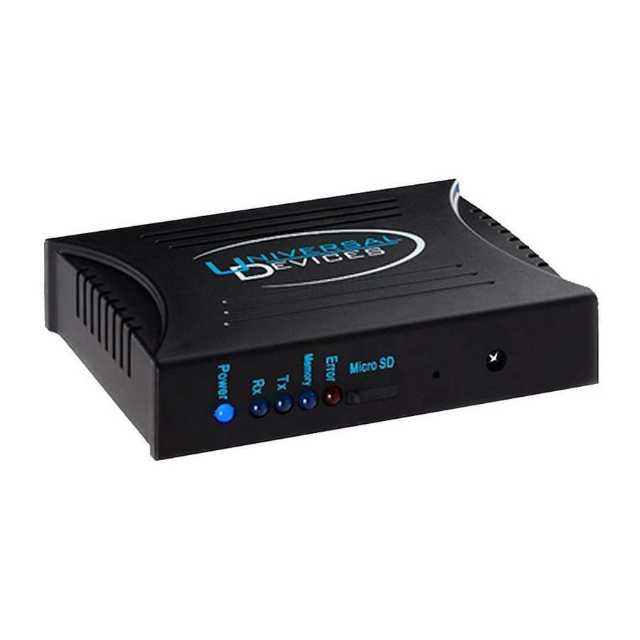
Page 71: Appendix A: Front And Rear Panel Leds
Appendix A: Front and Rear Panel LEDs Front Panel LEDs: Understanding the ISY’s front panel (see below) LEDs can be helpful when troubleshooting problems. Figure 73 ISY Front Panel Here is a table that helps explain each LED and LED combinations: LED or Combination Indicated Status Power on steady The PWR LED indicates that the ISY has power, either through the... - Page 72 Rear Panel LEDs: There are also 2 LEDs on the rear of the ISY where the Ethernet cable attaches. One LED indicates a good network connection (should be on solid) while the other should flash with network activity. - 67 -...
-
Page 74: Appendix B: Factory Reset
Appendix B: Factory Reset There are only a few reasons why you might want to factory reset your ISY. In most cases, a factory reset will not help any problems you might be having. Please be sure to thoroughly investigate your problem before trying a factory reset. If possible, be sure to have a known good backup of your ISY’s configuration before factory resetting. -
Page 76: Appendix C: Replacing / Upgrading Your Sd Card
Appendix C: Replacing / Upgrading Your SD Card In some instances you may want to upgrade or replace your SD card. For example: You have purchased the ISY’s Networking Module and need more storage for the internal web server. You are experiencing a blinking ERR light which could indicated a bad SD card. The ISY supports up to a 16GB SD card. -
Page 77: Figure 74 Isy With Cover Removed
Figure 74 ISY with Cover Removed Once you screw the ISY back together, you will need to reload the firmware. Proceed to the paragraph labeled “Reloading The ISY Firmware and Restoring From Backup”. Reloading the ISY Firmware and Restoring From Backup Once you’ve replaced your ISY’s SD card, you will need to re-load the firmware as well as restore your configuration from a backup. - Page 78 After the firmware is installed your ISY will reboot. Please re-launch the Administrative Console and login: http://www.universal-devices.com/99i Click on the FILE pull-down menu, then RESTORE ISY and choose your last backup. - 73 -...
-
Page 80: Appendix D: Upgrading Your Firmware
Appendix D: Upgrading Your Firmware The ISY’s Administrative Console checks for latest release firmware automatically. When a new release is detected, you will be notified and given on-screen instructions on performing the update. In some cases, however, you may want to manually download and install a newer firmware. -
Page 82: Appendix E: Assigning A Static Ip Address To The Isy
Appendix E: Assigning a Static IP Address to the ISY If you wish to assign a static IP address to your ISY, please open the Configuration tab, then the System sub-tab. Uncheck the “Automatic (DHCP)” box and fill out the fields in the Network Settings section: Figure 75 Assigning a Static IP Address To avoid IP address conflicts, be sure to choose an address outside of the DHCP range set... -
Page 84: Appendix F: Insteon Device Notes
Appendix F: INSTEON Device Notes Some INSTEON devices require special care when used with the ISY. Some need to be added to the system in a specific way, and some have unique options available when configuring with the ISY. This section details some of this information and more. As always, please refer to the manufacturer’s documentation first. -
Page 85: Motion Sensor
Momentary: A - The relay will close momentary. If it is Linked while On it will respond to On. If it is Linked while Off it will respond to Off. Momentary: Look at Sensor - If the sensor is On the relay will close momentarily when an On command is received. - Page 86 Since the Motion Sensor is a battery-saving RF device, you must put the device into linking mode to add it to the ISY (and make any changes to the device, such as adding/removing from scenes). Please follow the on-screen instructions to put the Motion Sensor into linking mode when prompted (hold SET button for 5 seconds).
- Page 87 There is a Program Action available to synchronize the Thermostat time with that of the ISY. Thermostat Adapter Older INSTEON Thermostat Adapters cannot act as controllers, thus they do not notify the ISY of any state changes. To get the most current information from your thermostat, we recommend using an ISY Program to poll the device periodically.
-
Page 88: Appendix G: Sample Isy Programs
Appendix G: Sample ISY Programs This section contains some sample ISY Programs to get you started. Periodically poll your Thermostat Adapter: From 12:00:00AM 24 hours Then Repeat Every 15 minutes Wait 10 minutes Set 'Thermostat' Query Else - No Actions - (To add one, press 'Action') Front door light ON 20 minutes after sunset, OFF at 10pm: From Sunset + 20 minutes 10:00:00PM (same day) - Page 89 Notify you of extreme temperature conditions: Status 'Thermostat' > 90° (Temperature) Or Status 'Thermostat' < 60° (Temperature) Then Send Notification to All Else - No Actions - (To add one, press 'Action') Turn driveway lights ON and OFF with an X10 remote: X10 'A2/On (3)' is Received And X10 'A2/Off (11)' is not Received Then...
-
Page 90: Appendix H: Troubleshooting Insteon Communication Issues
Appendix H: Troubleshooting INSTEON Communication Issues It is important to have a pair of INSTEON AccessPoints or other INSTEON RF devices (or an INSTEON-compatible hardwired coupler) installed to ensure good communications between both legs of power in your home. See Smarthome’s documentation for ensuring your AccessPoints are installed on opposite legs of power.
Need help?
Do you have a question about the ISY-99i Series and is the answer not in the manual?
Questions and answers