
Related Manuals for Value Hobby AVIATOR 25 ARF


Summary of Contents for Value Hobby AVIATOR 25 ARF
-
Page 1: Instruction Manual
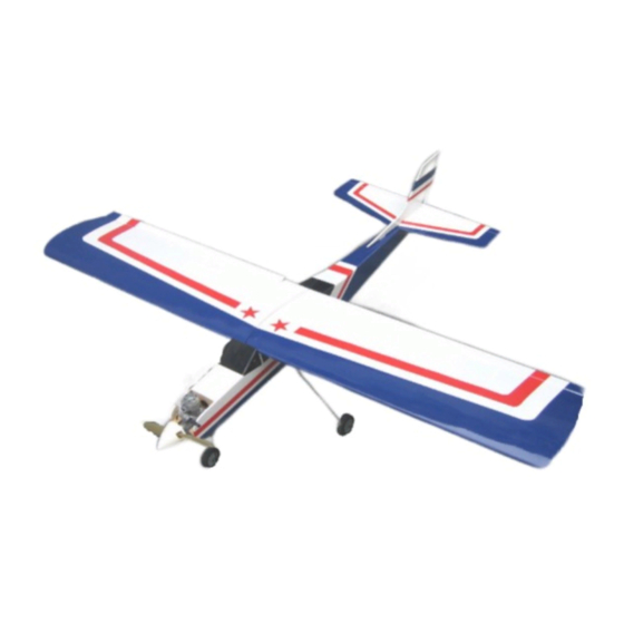
AVIATOR 25 ARF Almost Ready-to-Fly Instruction Manual Specifications Wingspan: 54.3 in (1380mm) Length: 45.2 in (1150mm) Wing Area: 438 sq in (34sq dm) Flying Weight: 3.8 b (1700g) -
Page 2: Dear Customer
This model should be built and flown by an experienced pilot and only flown at AMA sanctioned sites. Value Hobby guarantees this model to be free of defects in materials and workmanship at the date of purchase. This warranty does not cover any parts damaged by use or modifications. In no way shall Value Hobby’s liability exceed the original cost of the purchased model. -
Page 3: Safety In Flying
Examination Unpack your airplane and examine the components. Check for damage of any kind. If you see any damage, please contact Value Hobby immediately. Covering Your airplane was packed in plastic at the factory without any wrinkles in the covering. You may notice some wrinkles now;... - Page 4 Wrinkles in the covering DO NOT affect flight performance. Remove the canopy before attempting to use heat on your covering! The canopy is made of thermo-activated plastic and WILL deform with the application of heat. Do not apply heat to the canopy. If you need to clean your airplane, we recommend using a damp towel.
-
Page 5: Parts Table
Configuration Model Quantity Radio 4 channel GForce G15 Brushless Outrunner Motor(2820 Motor Size KV800-1100) Speed Control 60A PRO Brushless ESC with UBEC Recommended GForce Elite Series 35C 2200mAh 3S11.1V or 4S14.8V Battery(LiPO) LiPO Prop Size APC 14X7 or APC 13 X6.5 servos Universal Servo Y-Harness (300mm)11.8-Inch (Futaba Y-Harness... -
Page 6: Section 1: Landing Gear Installation
Section 1: Landing Gear Installation Step 1: Locate the main landing struts,wheels,wheel collars,setscrews and landing gear straps, and attach the both left and right wheel to the landing struts required parts install as shown Repeat the steps to install the other wheel to the landing gear strut... - Page 7 Step 2. Attach the landing gear to the fuselage,as shown use a knife to remove the covering from the slot on the bottom of the wing Attach the main landing gear to the fuselage as shown Check to be sure that all the parts are properly secured...
- Page 8 Step 3 .Locate the nose landing strut, wheel, whell collars, setscrews, steering arm and attach the wheel to the landing strut.as shown The nose landing gear parts Install as shown Install the nose landing gear on the front of the fuselage and tighten the bolts...
-
Page 9: Section 2: Stabilizer Installation
Section 2: Stabilizer Installation Step 1 .Locate the Horizontal Stabilizer and elevator, attach the elevator to the stabilizer, and slide stabilizer into the slot in the fuselage. Center the stabilizer in the fuselage(A=A’), and check the tips of the stabilizer are an equal distance from the a point centered at the front of the fuselage(B=B’) Step 2 .Locate the vertical stabilizer and rudder, attach the rudder to stabilizer, and slide stabilizer into the slot in the fuselage. - Page 10 Step 3 .Rudder elevator pushrod horn and servos installation, two standard servos(36g) are required...
-
Page 12: Section 3: Wing Installation
Section 3: Wing installation Step 1.Locate the parts as shown in the picture. two standard servos(36g) and Y-harness are required (needed to buy separately) Step 2. Attach the aileron to the wing and install the servo into the aileron as shown... - Page 13 Step 3. Pushrod and horn installation as shown...
- Page 14 Step 4.Repeat the steps 1-3 to finish installation of the servos. Use the epoxy to glue the two wing panel together. Use the clip and gummed paper to ensure the right alignment before the epoxy fully cures...
-
Page 15: Section 4: Nitro Motor Installation
Section 4: Nitro Motor Installation Step 1. Locate the parts required shown in the picture below... - Page 16 Step 2 . Nitro Motor installation as shown...
- Page 17 Step 3.The pushrods and servos installation as shown Step 4.Fule tank installation as shown...
-
Page 18: Section 5: Electric Motor Installation
Section 5: Electric Motor Installation Step 1. Locate the Motor box parts Motor box parts Step 2. Use the Epoxy to glue the parts to the fuselage as shown in the pictures below... - Page 19 Note: the scribed line marks where the parts should be glued...
- Page 20 Section 3. Electric Motor And ESC Installation Step 1. Locate the motor and ESC. (Not included) Step 2. Mark the motor mounting points...
- Page 21 Step 3. Drill through the marked points Step 4. Use the bolts to secure the motor to he motor box.(bolts needed to buy separately) Step 5. Drill a hole on the side of the fuselage for the ESC connection to battery as shown...
-
Page 22: Section 6 : Attaching Whe Wing To The Fuselage
Section 6 : Attaching Whe Wing To The Fuselage Step 1.Locate the wood strap, put it on the top of the wing and use the hobby knife to remove the covering, then glue the strap to the wing, at last use the bolts to secure the wing to fuselage. as shown below. -
Page 23: Section 7: Check Assembly
Section 7: Check Assembly Adjust the airplane to be as close as possible the description in the pictures below. Connect the servo system and ESC to your receiver, turn on the transmitter and power, check your RC system, motor and servos,. Make sure that all surfaces and all hardwares are secured properly. -
Page 24: Section 8: Setting Cg And Control Throws
Section 8: Setting CG and Control Throws Recommended CG For the first flights, the recommended Center of Gravity location is 79mm behind the leading edge of the wing against the fuselage. Use the battery pack, moving it forward or backward, to achieve the correct balance.
Need help?
Do you have a question about the AVIATOR 25 ARF and is the answer not in the manual?
Questions and answers