Table of Contents
Advertisement
Quick Links
Advertisement
Table of Contents

Related Manuals for Value Hobby Stylus Sport 60


Summary of Contents for Value Hobby Stylus Sport 60
-
Page 1: Instruction Manual
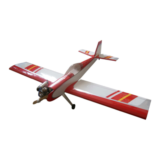
Stylus Sport 60 Stylus Sport 60 Stylus Sport 60 Stylus Sport 60 Almost-Ready-to-Fly Instruction Manual Specifications Wingspan: 70.9 in (1800mm) Length: 56.2in (1428mm) Wing Area: 795.1sq in (51.3sq dm) Flying Weight (GP): 7.28lbs (3300g) Flying Weight (EP): 6.72lbs (3050g) -
Page 2: Dear Customer
Further, Value Hobby reserves the right to modify this warranty without notice. Value Hobby has no control over the final stages of assembly or the material used for the final assembly. No liability shall be assumed nor materials used for the final user-assembled product. By the act of using the final product the user accepts all resulting liability. -
Page 3: Safety In Flying
Examination Unpack your airplane and examine the components. Check for damage of any kind. If you see any damage, please contact Value Hobby immediately. Covering Your airplane was packed in plastic at the factory without any wrinkles in the covering. You may notice some wrinkles now;... -
Page 4: Recommended Setup
www.valuehobby.com/stylus-sport-60.html Recommended Setup Configuration Model Radio 4 channel Motor Size GForce G46 Brushless Outrunner Motor 600KV) Speed Control 80A Brushless ESC Recommended GForce 40C 3300mAh 4S 14.8V LiPO Battery LiPO Prop Size 14 X 7 or 15 X 6 5 (nitro) Servos Standard servos 4 (electric) - Page 5 www.valuehobby.com/stylus-sport-60.html Accessories: Pack1: Engine mount-59x80mm (2.3x3.1in) 1 pair Pack5: Screw-M3*25mm (1.0in) 4pcs Servo hatch 2pcs Washer-Φ4mm (0.16in) 4pcs Servo mounting block 10x15x20mm (.4x.6x.8in) 4pcs Fuel tank assembly-360cc 1pcs Self-tapping screw-M2.5*8 mm (.3in) 12pcs Cable tie-350mm (13.8in) 2pcs Pack6: Pack2: Aileron Servo pushrodΦ1.8*150mm (5.9in) 2pcs Motor Mount Elevator servo pushrod-Φ1.8*900mm (35.5in) 1pcs Socket cap machine screw-M4*16mm (.6in) 4pcs...
-
Page 6: Section 1: Aileron Installation Required Parts And Hardware
www.valuehobby.com/stylus-sport-60.html Section 1: Aileron Installation Section 2: Aileron Servo Installation Required Parts and Hardware: Required parts and hardware: Wing panels Wing panels Ailerons Servo hatch 2pcs Hinges 8pcs Servo mounting blocks 4pcs Self-tapping screw M2.5*8 mm (.3in) 12pcs Step1. Locate the left aileron and four hinges. Slide Aileron servo 2pcs (sold separately) the hinges into the precut hinge slots in the leading Servo extension 2pcs (sold separately) - Page 7 www.valuehobby.com/stylus-sport-60.html Step3. Glue the two blocks onto the servo hatch. Step6. Use four M2.5*8mm (.3in) self-tapping screws to secure the servo to the mounting blocks. Step4. Use a 1.5mm (.06in) drill bit to drill two holes on the hatch as shown. The location for the holes should be in the central point of the blocks.
-
Page 8: Section 3: Aileron Linkage Installation Required Parts And Hardware
www.valuehobby.com/stylus-sport-60.html Step8. Use a 1.5mm (.06in) drill bit the drill the Section 3: Aileron Linkage Installation mounting hole as shown. Required parts and hardware: Aileron Servo pushrodΦ1.8*150mm (5.9in) 2pcs Keeper 2pcs Clevis 2pcs Control horn 2pcs Nut plate 2pcs Philips roundhead screw M2*16mm (.6in) 4pcs Step1. -
Page 9: Section 4: Wing Installation Required Parts And Hardware
www.valuehobby.com/stylus-sport-60.html Step3. Use two M2*16mm (.6in) Phillips round head Section 4: Wing Installation screws and nut plate to install control horn on the Required parts and hardware: aileron. Wing panels Wing joiner 1pcs Wing bolts plate Philips roundhead screw M4*35mm (1.4in) 2pcs Washer Φ4 2pcs Step1. - Page 10 www.valuehobby.com/stylus-sport-60.html Step4. Use a brush to apply some epoxy to the exposed wood on the wing foot and the other half of the joiner. Step8. Use a hobby knife to trim the covering inside the lines drawn in the previous step. Step5.
-
Page 11: Section 5: Horizontal Stabilizer & Elevator Installation Required Parts And Hardware
www.valuehobby.com/stylus-sport-60.html Section 5: Horizontal Stabilizer & Step4. Use a hobby knife to trim the covering inside the lines drawn in the previous step. Elevator installation Required parts and hardware: Horizontal stabilizer Elevator Joiner Step1. Use the ruler and a felt-tipped pen to locate the center point in the trailing edge of the horizontal stabilizer. - Page 12 www.valuehobby.com/stylus-sport-60.html Step7. Use a 2.5mm (.1in) drill bit to drill the hole in the elevator as shown. Step11. Repeat step 7 to step 8 on the other elevator panel. Step8. Insert three hinges into the slot in the leading edge of the elevator. Step12.
-
Page 13: Section 6: Fin, Rudder And Tail Wheel Installation Required Parts And Hardware
www.valuehobby.com/stylus-sport-60.html Section 6: Fin, Rudder and Tail wheel Step3. Repeat the step 12 and 13 for the other triangle stock. Installation Step4. Use the epoxy to glue two triangle stock to the Required parts and hardware: fin as shown. Rudder Triangle Stock 2pcs Fin mounting block Tail wheel assembly... - Page 14 www.valuehobby.com/stylus-sport-60.html Step6. Use a knife to remove the coverings inside the Step8. Glue the fin onto the horizontal stabilizer. lines drawn in the previous step. (Note: use a square to make sure that the fin is perpendicular to the horizontal stabilizer). Step9.
-
Page 15: Section 7: Elevator & Rudder Servo And Linkage Installation Required Parts And Hardware
www.valuehobby.com/stylus-sport-60.html Step11. Use a 2.5mm (.1in) drill bit to drill the hole Section 7: Elevator & Rudder Servo and and use a hobby knife to cut a groove as shown. Linkage Installation Required parts and hardware: Pushrod Φ1.8*900mm (35.4in) 2pcs Clevis 2pcs Control horn 2pcs Nut plate 2pcs... -
Page 16: Section 8: Engine Installation Required Parts And Hardware
www.valuehobby.com/stylus-sport-60.html Step27. Center the elevator and servo arm. Attach the Section 8: Engine Installation pushrod to the pushrod connector. Required parts and hardware: Tank assembly 360cc Engine mount 1 pair Phillips roundhead screw M4*25mm (1.0in) 4pcs Washer Φ4 4pcs Step1. Attach the engine to the firewall with four M4*25mm (1.0in) roundhead screws. -
Page 17: Section 9: Fuel Tank Installation
www.valuehobby.com/stylus-sport-60.html Step4. Install the throttle servo on the servo tray. Step2. Fit the stopper assembly into the tank with the Electronically adjust the throttle arm and servo arm vent line pointing toward the top of the tank, but not to make them move rightly. Secure the pushrod to touching. -
Page 18: Section 10: Electric Motor Installation
www.valuehobby.com/stylus-sport-60.html Section 10: Electric Motor Installation Section 11: Landing Gear Installation Required parts and hardware: Required parts and hardware: Electric motor mount Landing Gear 1pcs Socket cap machine screw-M4*16mm (.6in) 4pcs Philips roundhead screw-M4*12mm (.5in) 3pcs Nut M4 4pcs Washer-Φ4mm (.16in) 3pcs Washer---Φ4mm (0.16in) 4pcs Main wheels-Φ65mm (2.6in) 2pcs Socket cap machine screw-M4*35mm (1.4in) 2pcs... -
Page 19: Section 11: Canopy Installation
www.valuehobby.com/stylus-sport-60.html Step3. Use three M4*12mm (.5in) Phillips roundhead Step2. Use four M2.5*8mm(.3in) self-tapping screws screw and three Φ4mm (.16in) washers to secure the Install the canopy to the fuselage as shown. landing gear to the fuselage as shown. Section 11: Setting CG and Control throws Recommended CG For the first flights, the recommended Center of... - Page 20 www.valuehobby.com/stylus-sport-60.html www.valuehobby.com 2012-11-6 - 20 -...
Need help?
Do you have a question about the Stylus Sport 60 and is the answer not in the manual?
Questions and answers