Table of Contents
Advertisement
Quick Links
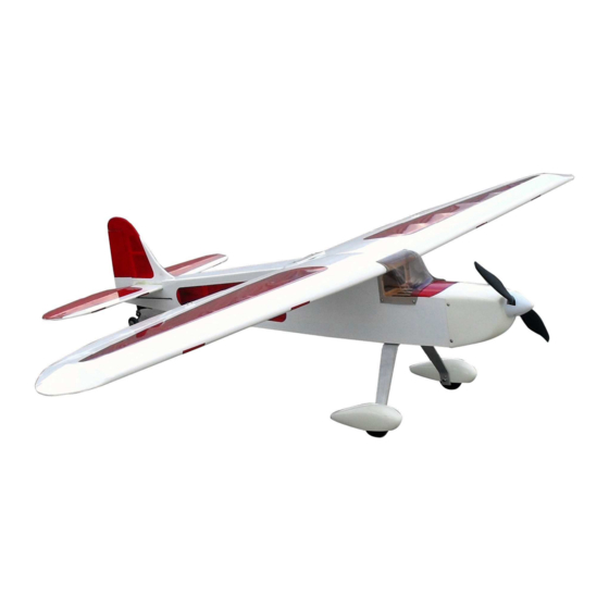
Aviator-Pro 60
Almost-Ready-to-Fly
Instruction Manual
Specifications
Wingspan: 76.8 in (1950mm)
Length: 53 in (1350mm)
Wing Area: 775sq in (50sq dm)
Flying Weight: 6.6lb (3000g)
Product Highlights
• Light weight balsa and plywood construction
• Fiberglass cowling and fiberglass wheel pants
• Easy to setup for either nitro or electric power
• Available in red or blue covering scheme
• Rubber tires and plastic spinner included
Advertisement
Table of Contents

Related Manuals for Value Hobby Aviator-Pro 60 ARF


Summary of Contents for Value Hobby Aviator-Pro 60 ARF
-
Page 1: Instruction Manual
Aviator-Pro 60 Almost-Ready-to-Fly Instruction Manual Specifications Wingspan: 76.8 in (1950mm) Length: 53 in (1350mm) Wing Area: 775sq in (50sq dm) Flying Weight: 6.6lb (3000g) Product Highlights • Light weight balsa and plywood construction • Fiberglass cowling and fiberglass wheel pants •... -
Page 2: Dear Customer
Dear Customer, Congratulations on your purchase of Aviator-Pro 60 ARF from Value Hobby. We thank you for your generous support, and hope you enjoy your new airplane. At Value Hobby, we hope to offer competitive prices, good performance, and products that you can setup and use with ease. -
Page 3: Safety In Flying
Examination Unpack your airplane and examine the components. Check for damage of any kind. If you see any damage, please contact Value Hobby immediately. Covering Your airplane was packed in plastic at the factory without any wrinkles in the covering. You may notice some wrinkles now;... - Page 4 www.valuehobby.com RECOMMENDED RADIO EQUIPMENT: Product Quantity Radio 6 Channel FLY-RC-1310 5 for nitro, Servo Towerpro MG996R Standard Servo TWP-SV-0372 4for electric Universal Servo Y-Harness 12-Inch (Futaba "J" and JR Y-Harness AMS-AC-0869 Compatible) Universal Servo Extension 24-Inch (Futaba "J" and JR Extension AMS-AC-0564 Compatible)
- Page 5 www.valuehobby.com Main Parts of the Airplane...
-
Page 6: Section 1: Aileron Installation
Section 1: Aileron Installation Section 2: Aileron Servo & Control Horn Installation Step1. Locate the aileron hinges from the hardware pack, and insert the hinges in the slots in the Step1. Locate the items shown in the picture below. trailing edge of the wing. (Servos and Y-Harness sold separately). - Page 7 www.valuehobby.com Step4. Position the servo on the servo hatch, and Step7. Use the screws to secure the servo to the the servo arm should be centered in the slot. Once mounting blocks. satisfied, use a felt-tipped pen to mark the location for servo mounting blocks.
-
Page 8: Section 3: Wings Installation
www.valuehobby.com Step10. Use four self-tapping screws to install the Step13. Use the control horn backplate and two servo hatch to the wing. (Note: in this step, first mounting bolts to secure the control horn to the you need to drill the holes for the mounting aileron. -
Page 9: Section 4: Horizontal Stabilizer & Elevator Installation
www.valuehobby.com Step3. Make sure the wing panels fit tightly. When Section 4: Horizontal Stabilizer & the epoxy cured, position the wing bolt plate on Elevator Installation the wing, aligning the holes with those in the wing. Use a hobby knife to trim the covering along the Step1. - Page 10 www.valuehobby.com Step4. Position the elevator against the stabilizer Step7. Insert the hinges into the pre-cut slots in the on the work surface; Use a felt-tipped pen to mark elevators and saturate each of the hinges with thin the position where the joiner wire enters the CA.
-
Page 11: Section 5: Rudder And Tail Wheel
www.valuehobby.com Step10. Once the requirements satisfied in step9, Step3. Locate the tail wheel assembly. apply thin CA on both the top and bottom of the stabilizer to secure the stabilizer onto the fuselage. (It’s better to use epoxy in this step.) Step4. -
Page 12: Section 6: Rudder And Elevator Servo & Linkage Installation
www.valuehobby.com Step7. Glue the hinges into the slots in the rudder. Section 6: Rudder and Elevator Servo & Test fit the tail gear wire into the rudder, and use Linkage Installation the epoxy to secure it. Step1. Locate the necessary parts for this section. (Servos sold separately) Step8. - Page 13 www.valuehobby.com Step4. Thread the clevis a min of 10 turns on the Step7. Place 2-3 drops of thin CA into each of the pushrod wire. Connect the clevis to the control holes to harden the wood. horn. (In this step you can slide a tube over the clevis so it will not accidentally open in flight).
-
Page 14: Section 7: Nitro Motor Installation
www.valuehobby.com Step5. Prepare an assembled servo arm with Section 7: Nitro Motor Installation pushrod connector as shown. Step1. Locate the necessary parts for this section. Skip this section if you are using an electric motor. Step6. Center the throttle stick and trim with both the receiver and transmitter on. -
Page 15: Section 8: Fuel Tank Installation
www.valuehobby.com Section 8: Fuel Tank Installation Step1. Skip this section if you are using an electric motor. The fuel tank can be assembled as a two line system consisting of a vent (pressure) line to the muffler and a carburetor line. Filling and emptying of the tank would need to be done through the carburetor line, or an optional fuel fill valve. -
Page 16: Section 9: Electric Motor Installation
www.valuehobby.com Section 9: Electric Motor Installation Section 10: Cowling and Spinner Installation Step1. Secure the motor box to the firewall. Step1. Position the cowling into the fuselage. Drill the four mounting holes as shown. Step2. Install your brushless motor onto the motor Step2. -
Page 17: Section 11: Landing Gear & Wheels Installation
www.valuehobby.com Step4. Repeat steps 2 for the other wheel. Section 11: Landing Gear & Wheels Installation Step1. Secure the axle to the landing gear using pliers and hex wrench. Step5. Slide the wheel pant over the wheel. Step2. Slide a wheel collar on the axle, and tighten the wheel collar using a grub screw. -
Page 18: Section 12: Canopy Installation
www.valuehobby.com Section 12: Canopy installation Section 13: Setting CG and Control Throws Locate the required parts and trim the edges of the canopy as needed. Use four screws to secure the Recommended CG canopy to the fuselage. For the first flights, the recommended Center of Gravity location is 116mm behind the leading edge of the wing against the fuselage. - Page 19 Finally... Enjoy Your Aviator-Pro 60 ARF Have a nice flight!
Need help?
Do you have a question about the Aviator-Pro 60 ARF and is the answer not in the manual?
Questions and answers