
Subscribe to Our Youtube Channel
Related Manuals for Value Hobby LASER


Summary of Contents for Value Hobby LASER
-
Page 1: Instruction Manual
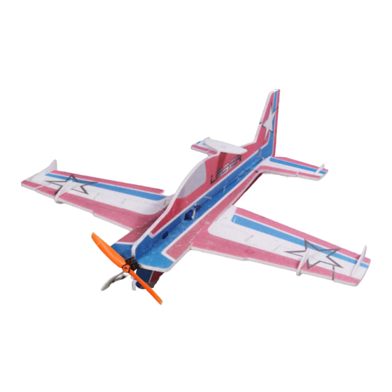
8mm LASER Instruction Manual Specifications Wingspan: 800 mm (31.5 in) Length: 790 mm (31.1 in) Wing Area: 14.6sq dm (226.3sq in) Flying Weight: Approx. 250 g (8.5oz) -
Page 2: Dear Customer
Further, Value Hobby reserves the right to modify this warranty without notice. Value Hobby has no control over the final stages of assembly or the material used for the final assembly. No liability shall be assumed nor materials used for the final user-assembled product. By the act of using the final product the user accepts all resulting liability. -
Page 3: Safety In Flying
Set Metric Allen Wrenches Scissors Small Pliers Wire Cutters Masking tape Optional – Heat gun Before Starting Assembly Examination Unpack your airplane and examine the components. Check for damage of any kind. If you see any damage, please contact Value Hobby immediately. -
Page 4: Main Parts
Main Parts 1. Wings 2. Horizontal fuselage 3. Vertical fuselage 4. Tail 5. Foam accessories... - Page 5 Accessories: List: 1. Fiberglass parts including motor mount x 1, control horn x 3, elevator control horn x1. wheel x 2, landing gear mounting plate x1, aileron servo arm extension x 1, rudder servo arm extension x 1, elevator servo arm extension x 1, pushrod support x 9 2.
- Page 6 RECOMMENDED RADIO EQUIPMENT Product Quantity Radio Flysky T6 Transmitter FLY-RC-2563 Servo TWP-SV -0352 Towerpro SG50 Micro Servo for rudder and elevator RECOMMENDED POWER SETUP Product Motor GForce T2206-1500KV Brushless Outrunner Motor VHB-MT-3200 Hobbywing Flyfun 12A ESC HWG-SC-0236 Battery GForce 50C 500mah 3S LiPO...
-
Page 7: Section1. Airframe Assembly
Step5. Place the tail and horizontal fuselage in Section1. Airframe Assembly position on a work surface. Step1. Use foam safe glue to glue the wings to the fuselage. Step6. Glue that two fiberglass plates to the fuselage. Step2. Glue the carbon fiber square tubing to the pre-cut slot. -
Page 8: Section2. Servo Linkage Installation
Step9. Install aileron servo, elevator servo and rudder Step13. Position the zigzag onto the fuselage as servo onto the fuselage from the nose to tail. shown. Start to glue it at the tail and work your way slowly toward the front of the fuselage. - Page 9 Step3. Cut a slot for the horn along the marked line Step7. Slide four guides to the 400mm (15.7-inch) on the aileron. CF rod and attach a z-bend wire to one end of the Glue the horn with z-bend wire to the aileron.
-
Page 10: Section3. Landing Gear Installation
Step11. Connect the z-bend wire to the elevator Section3. Landing Gear Installation control horn Step1. Assemble the landing gears as shown. Step2. Glue the landing gear mount to the Step10. Use the foam safe glue to glue the control fuselage. -
Page 11: Section4. Motor And Prop Installation
Section4. Motor and Prop Installation Section5: Set up CG and control thro Step1. Install the 2206 motor to the motor mount. The recommended CG is 218mm (8.6in) from the nose of the fuselage. Exponential for 3D flying Step2. Install 8 x 4 prop to the motor. - Page 12 www.valuehobby.com 2014-10-15...
Need help?
Do you have a question about the LASER and is the answer not in the manual?
Questions and answers