
Related Manuals for Value Hobby 37in Electric Extra Sportster


Summary of Contents for Value Hobby 37in Electric Extra Sportster
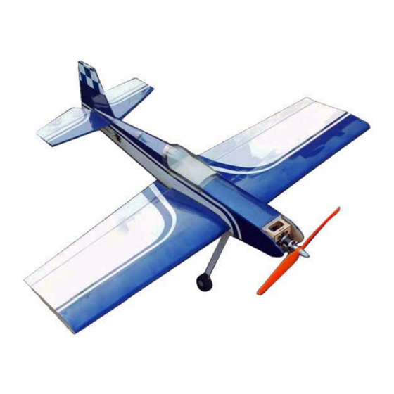
- Page 1 37in Electric Extra Sportster ARF (Almost-Ready-to-Fly) Specifications Wingspan: 37 in (940mm) Length: 35 in (890mm) Wing Area: 350 sq in (22.6 sq dm) Flying Weight: 1.85 lb (840g)
- Page 2 This model should be built and flown by an experienced pilot and only flown at AMA sanctioned sites. Value Hobby guarantees this model to be free of defects in materials and workmanship at the date of purchase. This warranty does not cover any parts damaged by use or modifications. In no way shall Value Hobby’s liability exceed the original cost of the purchased model.
- Page 3 Examination Unpack your airplane and examine the components. Check for damage of any kind. If you see any damage, please contact Value Hobby immediately. Covering Your airplane was packed in plastic at the factory without any wrinkles in the covering. You may notice some wrinkles now;...
-
Page 4: Configuration Table
Configuration table Configuration Model Quantity Radio 4 channel GForce E400 Brushless Outrunner Motor Motor Size TPB-MT-0164 (2815-1200KV) Speed Control Hobbywing FlyFun 30A Brushless ESC HWG-SC-0238 Recommended GForce 30C 2200mAh 3S 11.1V LiPO RFI-LP-0302 Battery(LiPO) Prop Size Towerpro 9 X 6 Electric Slow Flyer Prop TWP-MP-0473 servos Towerpro MG90S Metal Gear Micro Servo... - Page 5 ASSEMBLY Step 1: Locate the landing gear, wheels, nuts, bolts and washers as shown below. Assemble the landing gear and wheels as shown below. Please note the nut on the end is a lock-nut. Step 2: Secure the landing gear on the fuselage using socket head screws. Step 3: Find the horizontal stab and the elevator.
- Page 6 Step 4: Cut away the covering over the stab opening on the fuselage. Also remove the covering over the area on the elevator that goes into the fuselage. Slide the horizontal stab into the fuselage. Step 5: Use 3 hinges to secure the rudder to the vertical stab. Use the method to secure the vertical stab to the fuselage as you did with the horizontal stab.
- Page 7 Step 6: Adjust the horizontal stab so it’s perfectly level and perfectly centered. Step 7: You will use 8 hinges to secure the aileron to the wing, 4 hinges per aileron half. Apply CA to secure. Step 8: Find the control horn, pushrod, control horn bolts, and pushrod easy-connectors. Assemble the control horn as shown below.
- Page 8 Step 9: Install the electric motor on the motor mount. There is a removable panel on the bottom of the fuselage to allow the installation of battery, ESC, and other electronics. Step 10: Secure the canopy and the tail skid.
- Page 9 Step 11: As shown below, align the two dowels on the wing with the opening on the fuselage, then secure the wing by tightening the wing bolt. Step 12: Fine-tune the wing, horizontal and vertical stabs so the surfaces are all level and straight. Then use epoxy to secure the elevator and rudder to the fuselage.
- Page 10 Step 13: We recommend you set the CG at 65mm (2 ½ in) from the leading edge of the wing to start, and adjust the CG until it suits your preference. Step 14: We recommend the follow control throws to start off: Elevator: 5 - 10 degrees Ailerons:...
Need help?
Do you have a question about the 37in Electric Extra Sportster and is the answer not in the manual?
Questions and answers