
Related Manuals for Value Hobby Yak-54


Summary of Contents for Value Hobby Yak-54
-
Page 1: Instruction Manual
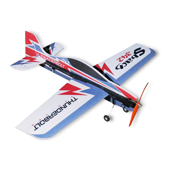
5mm EPP 3D Profile Airplane ARF Instruction Manual Sbach-342 Yak-54 Specifications Wing Span: 34.0 in (863 mm) Length: 36.0 in (915 mm) Wing Area: 294.5 sq in (19 sq dm) Flying Weight: 6.7-8.1oz (190-230 g) -
Page 2: Dear Customer
Further, Value Hobby reserves the right to modify this warranty without notice. Value Hobby has no control over the final stages of assembly or the material used for the final assembly. No liability shall be assumed nor materials used for the final user-assembled product. By the act of using the final product the user accepts all resulting liability. -
Page 3: Safety In Flying
Set Metric Allen Wrenches Scissors Small Pliers Wire Cutters Masking tape Optional – Heat gun Before Starting Assembly Examination Unpack your airplane and examine the components. Check for damage of any kind. If you see any damage, please contact Value Hobby immediately. - Page 4 www.valuehobby.com/5mm-epp.html RECOMMENDED RADIO EQUIPMENT Product Quantity Flysky T6 6CH transmitter and receiver set FLY-RC-2563 Radio Towerpro SG90 9g servo for aileron TWP-SV-0357 Servo Towerpro SG50 5g servo for rudder and elevator TWP-SV-0352 RECOMMENDED POWER SETUP Product Motor Gforce Emax CF2812 brushless motor EMX-MT-0166 Hobbywing Flyfun 12A brushless ESC HWG-SC-0236...
- Page 5 www.valuehobby.com/5mm-epp.html Yak 54 Main Parts Sbach342 Main Parts...
- Page 6 www.valuehobby.com/5mm-epp.html Accessories (Same for two planes) 1. Landing gear x2 2. Wheel x 2 3. Heat shrink tube x 2 4. Control horn x 4 set 5. Pushrod connector x 4 6. Screw x 4 7. Steel wire with z-bend x 8.
-
Page 7: Section1. Airframe Assembly
Step3. Install two side force generators to the wing. Section1. Airframe Assembly Step1. Place the four parts of the horizontal fuselage in position on a flat work surface to make A=B. Use thin CA to glue them together. Insert and glue the NO.15, NO.16 and NO.17 carbon fiber strips into the slots in the fuselage. -
Page 8: Section3. Carbon Rods Installation
www.valuehobby.com/5mm-epp.html Section3. Carbon Rods Installation Section4. Tail Skid Installation Glue NO1. to NO 11 carbon fiber rods to the Glue one piece of NO.15 carbon fiber strip to the fuselage and wing as shown. fuselage as the tail skid. (The slots for CF rods were pre-cut in the factory.) Section5. - Page 9 www.valuehobby.com/5mm-epp.html Step5. Use the heat shrink tube to connect the NO.12 carbon fiber rod and the steel wire with z bend as the pushrod wire. Step3. Install the aileron servo arm. (Center the servo electronically in advance.) Step4. Install two 5g servos to the fuselage. (Elevator and rudder servo) Step6.
- Page 10 www.valuehobby.com/5mm-epp.html Step7. Glue the control horn mount to the aileron. Step11. Finish the rudder and elevator servo linkage installation in the same procedures as aileron servo. (Note: two pushrod guides need to be installed to ensure the pushrods won’t be twisted.) Step8.
-
Page 11: Section6. Motor Installation
www.valuehobby.com/5mm-epp.html Section6. Motor Installation Center of gravity Step1. Glue the EPP foam motor mount to the The recommended CG is 229mm (9in) from the plywood mount. airplane front end point. Exponential for 3D flying Step2. Use the hot glue to secure the motor mount to the fuselage Step3. - Page 12 www.valuehobby.com/5mm-epp.html www.valuehobby.com 2013-08-20...
Need help?
Do you have a question about the Yak-54 and is the answer not in the manual?
Questions and answers