Advertisement
Quick Links
Easy
Stick-25
Easy
Stick-25
Easy
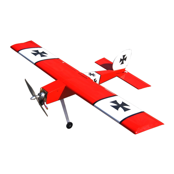
Easy Stick-25
Stick-25 ARF
Instruction
Instruction
Manual
Manual
Instruction
Instruction Manual
Manual
Specifications
Specifications
Specifications
Specifications
Wingspan: 48 in (1220mm)
Length: 35.8 in (910mm)
Wing Area: 403 sq in (26sq dm)
Flying Weight: 2.98lb--3.3lb(1350-1500g)
ARF
ARF
ARF
* * * *
1
Advertisement

Related Manuals for Value Hobby Easy Stick-25 ARF


Summary of Contents for Value Hobby Easy Stick-25 ARF
- Page 1 Easy Stick-25 Easy Stick-25 Easy Easy Stick-25 Stick-25 ARF Instruction Instruction Manual Manual Instruction Instruction Manual Manual Specifications Specifications Specifications Specifications * * * * Wingspan: 48 in (1220mm) Length: 35.8 in (910mm) Wing Area: 403 sq in (26sq dm) Flying Weight: 2.98lb--3.3lb(1350-1500g)
-
Page 2: Safety Assembly
In no way shall Value Hobby’s liability exceed the original cost of the purchased model. Further, Value Hobby reserves the right to modify this warranty without notice. Value Hobby has no control over the final stages of assembly or the material used for the final assembly. No liability shall be assumed nor materials used for the final user-assembled product. - Page 3 Assembly Examination Examination Examination Examination Unpack your airplane and examine the components. Check for damage of any kind. If you see any damage, please contact Value Hobby immediately. Covering Covering Covering Covering Your airplane was packed in plastic at the factory without any wrinkles in the covering. You may notice some wrinkles now; more likely, you will notice a few in a day or two or the first time you take the plane out to the flying field.
- Page 4 Recommended Recommended Recommended Recommended Setup Setup Setup Setup Product Product Model Model Product Product Model Model Radio At least 4 channel Motor GForce G15 Brushless Motor Speed Control 40A Brushless ESC Battery GForce 25C 1800—2200 mAh 3S11.1V LiPO Prop Size 10 X 7 or 11X 6 Aileron: 2 X mini servos 5 for nitro...
- Page 5 Aileron Aileron Installation Installation Aileron Aileron Installation Installation Step 2 Step 3 Use a pin vise and 1/16-inch (1.5mm) drill bit to Place a T-pin in the center of each hinge. drill a hole in the center of each hinge slot. Drill Insert the hinges in the slots in the trailing edge Step 1 holes for both the aileron and wing.
- Page 6 Step 4 Step 5 Step 6 Use the hinges to place the aileron in position. Saturate each of the hinges with thin CA. Make Flex the aileron up and down a number of Use a hobby knife to set the gap between the sure to glue both the top and bottom.
- Page 7 Step 1 Step 2 Aileron Aileron Aileron Aileron Servo Servo Servo Servo Installation Installation Installation Installation Use string to secure a 9-inch (230mm) servo Use a hobby knife and #11 blade to remove extension to the aileron servo the covering for the outboard servo in the Required Parts bottom of the wing.
- Page 8 Step 3 Step 4 Step 5 Tie the string around the servo lead. Pull the Position the servo in the wing with the servo Secure the servo in the wing using a #1 lead through the wing and out of the hole at the output shaft toward the aileron (or flap).
- Page 9 Step 7 Step 8 Step 9 Use a pin vise and 2mm drill bit to enlarge the Use a pin vise and a 5/64-inch (2mm) drill bit to With the control surface centered, use a felt- hole in the servo horn that is 1/2-inch (13mm) drill the two holes for the control horn screws.
- Page 10 Step 10 Use diagonal cutters to trim the pushrod wire 3/8-inch (9.5mm) above the bend. Secure the pushrod wire to the servo horn using a pushrod keeper. Use diagonal cutters to remove any unused servo arm from the servo horn. Step 11 Repeat Steps 1 through 10 to install the remaining servo.
- Page 11 Step 2 Step 3 Joining Joining Joining Joining the the Wing Wing Wing Wing Panels Panels Panels Panels Mark a center line on the joiner. It should slide Use 30-minute epoxy to glue the joiner into the into each wing panel up to the line. If not, lightly wing panels.
- Page 12 Step 4 Make sure the wing panels fit tightly together. Clean any epoxy using a paper towel and rubbing alcohol. Use low-tack tape to keep the panels tightly together while the epoxy cures. Important: Make sure the leading edge and trailing edges of the wing at the joint are aligned with each other.
- Page 13 Step 2 Step 3 Completing Completing Completing Completing the the Wing Wing Wing Wing Assembly Assembly Assembly Assembly Position the wing bolt plate on the wing, aligning Use 30-minute epoxy to glue the wing bolt the holes with those in the wing. Trace the outline plate to the wing.
- Page 14 Step 1 Step 2 Horizontal Horizontal Horizontal Horizontal Stabilizer Stabilizer Stabilizer Stabilizer Installation Installation Installation Installation Install the wing by aligning the dowels from the Secure the wing using two wing bolts. Tighten wing into the holes in the fuselage. the bolts using a screwdriver.
- Page 15 Step 3 Step 4 Step 5 Use a ruler to mark the center of the stabilizer. Check the alignment of the stabilizer to the wing. Use a felt-tipped pen to trace the outline of the Do not use the covering as a guide as it may not Position the stabilizer so the measurements from fuselage on the stabilizer.
- Page 16 Step 1 Step 2 Vertical Vertical Vertical Vertical Fin Fin Installation Installation Installation Installation Insert the fin in the slot at the rear of the Use a hobby knife and #11 blade to remove fuselage. Use a felt-tipped pen to trace the the covering from the fuselage and fin.
-
Page 17: Installation
Step 1 Step 2 Preparation Preparation Preparation Preparation for for Tail Tail Tail Tail Landing Landing Landing Landing Gear Gear Gear Gear Mark where it is 15mm from the tip of the rudder Use a hobby knife and #11 blade to cut a Installation Installation Installation... - Page 18 Step 3 Step 4 Step 5 Bend the rod 90 degrees as shown. Insert the tail gear wire into the rudder. It should Fit the rudder to the fin. Use a hobby knife and fit as shown. Use 30-minute epoxy to glue the #11 blade to check the hinge gap and that the wire into the fin.
- Page 19 Step 6 Step 7 Step 8 Use thin CA to glue the two hinges that secure Position the elevator against the stabilizer. Use a Insert a T-pin in the center of the six stabilizer the rudder and fin. Perform a pull test on the felt-tipped pen to mark where the tail wheel wire hinges.
- Page 20 Step 9 Step 10 Step11 Install the elevator against the stabilizer using Flex the elevator up and down a number of times Secure the tail landing gear to the horizontal the hinges. Set the hinge gap using a hobby to break in the hinges. stabilizer and install the wheel to the landing knife and #11 blade.
- Page 21 Step 1 Step 2 Radio Radio Radio Radio Installation Installation Installation Installation Use the hardware to mount the servos in the Slide a clevis retainer on a clevis, then thread fuselage. Note the servo tube near the rudder the clevis on the pushrod wire. Connect the Required Parts servo.
- Page 22 Step 3 Step 4 Use a pin vise and 5/64-inch (2mm) drill bit to With the rudder servo centered, attach the arm drill the holes for the screws. Use 2- 3 drops of to the servo. With the rudder centered, use a thin CA to harden the holes.
- Page 23 Step 5 Step 6 Trim the wire 3/8-inch (9.5mm) above the bend. Repeat Steps 2 through 8 to connect the elevator Use a pushrod keeper to secure the pushrod pushrod wire. When preparing the servo horn, wire to the rudder servo horn. use a hole that is 1/2-inch (13mm) from the center of the servo horn.
- Page 24 Step 1 Step 2 Landing Landing Landing Landing Gear Gear Gear Gear Installation Installation Installation Installation Attach the axle to the wheel. Then secure the Secure the assembled wheel axle to the wheel with a nut. landing gear. Required Parts...
- Page 25 Step 3 Step 4 Step 5 Repeat Steps 1 and 2 to attach the remaining Remove the covering for the main landing gear Secure the assembled landing gear to the wheel. When installing the gear, note the angle mount. fuselage using two M3*12 screw. of the gear.
- Page 26 Step 1 Step 2 Nitro Nitro Nitro Nitro Engine Engine Engine Engine Installation Installation Installation Installation Attach the engine mount rails to the firewall using Secure the engine to the mount rails.(2 stroke four M3*20socket head screws and four M3 engine is shown as an example) Required Parts washers.
- Page 27 Step 3 Step 4 Step 5 Install the propeller and spinner following the Slide the long and short aluminum tubes into the Use a #1 Phillips screwdriver to start the 3mm instructions provided with the engine. Never use stopper. The holes for these tubes are pre-made x 20mm machine screw.
- Page 28 Step 6 Step 7 Step 8 Slide the fuel tube on the short aluminum tube. Once the clunk line has been adjusted, tighten Install the throttle pushrod as shown The clunk will fit on the opposite end of the tube. the 3mm x 20mm machine screw with a #1 Insert the stopper in the tank and make sure the Phillips screwdriver to secure the stopper in the...
- Page 29 Step 9 Step 10 Insert the tank into the fuselage with the correct Position the nose cover plate on the fuselage. side facing up. Secure it with straps.
- Page 30 Step 2. Connect the ESC to the motor and Electronics Electronics Electronics Electronics Installation Installation Installation Installation secure it to the inside of the fuselage using hook and loop material. Actual ESC location Required Parts may vary. Step 1. Place the four 4-40 blind nuts on the inside of the firewall in the locations for your particular motor.
- Page 31 Step 3. Slide the propeller adapter onto the motor. Place the propeller onto the adapter, then a spinner cone onto the adapter and secure.
- Page 33 Setting Setting Control Control Throws Throws Setting Setting CG CG and and Control Control Throws Throws Recommended Recommended Recommended Recommended CG For the first flights, the recommended Center of Gravity location is 65 65mm mm behind the leading edge of the wing against the fuselage. Use the battery pack, moving it forward or backward, to achieve the correct balance.
Need help?
Do you have a question about the Easy Stick-25 ARF and is the answer not in the manual?
Questions and answers