
Related Manuals for Value Hobby Elite Model Aviator 75 ARF


Summary of Contents for Value Hobby Elite Model Aviator 75 ARF
-
Page 1: Instruction Manual
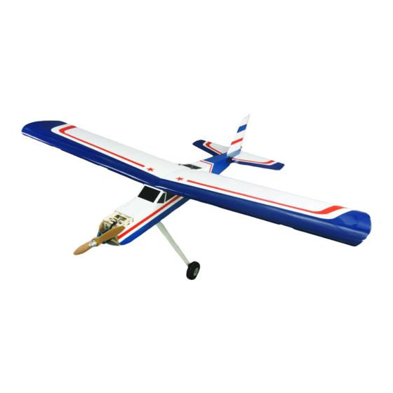
Aviator 75 ARF Instruction Manual Specifications Wingspan: 73.2 in (1860 mm) Length: 61.0 in (1550 mm) Wing Area: 961 sq in (62 sq dm) Weight: 8.7lbs (3930 g) - Page 2 Dear Customer, Congratulations on your purchase of our Elite Model Aviator 75 ARF from Value Hobby. We thank you for your generous support, and hope you enjoy your new airplane. At Value Hobby, we hope to offer competitive prices, good performance, and products that you can setup and use with ease.
-
Page 3: Required Items
Examination Unpack your airplane and examine the components. Check for damage of any kind. If you see any damage, please contact Value Hobby immediately. Covering Your airplane was packed in plastic at the factory without any wrinkles in the covering. You may notice some wrinkles now;... - Page 4 www.valuehobby.com/aviator-75-arf.html RECOMMENDED RADIO EQUIPMENT Product Quantity Radio Flysky i6 6CH transmitter and receiver set FLY-RC-4572 4 electric Servo Towpro MG996R standard servo TWP-SV-0372 5 nitro Servo Extension Universal Servo Extension Heavy Duty 18inch AMS-AC-0563 Y-Harness Universal Servo Heavy Duty Y-Harness 12in AMS-AC-0870 RECOMMENDED POWER SETUP Product...
- Page 5 www.valuehobby.com/aviator-75-arf.html Main Parts and Accessories: 1. Wing panels 2. Fuselage 3. Horizontal tail 4. Vertical tail...
- Page 6 www.valuehobby.com/aviator-75-arf.html 1. Engine rail mount x 1 set 2. M4*25 socket head screws x 4 21. 140x2mm aileron servo pushrod x 2 3. M4 blind nut x 4 22. 250x2mm elevator servo pushrod 4. M4 washer x 4 23. 250x2mm rudder servo pushrod 5.
-
Page 7: Section1. Aileron And Aileron Servo Installation
Section1. Aileron and Aileron Servo Installation Step1. Remove the covering from the servo Step4. Slide the aileron and wing together. The gap opening in the bottom of the wing using a hobby between the aileron and wing should be infinitely knife. - Page 8 www.valuehobby.com/aviator-75-arf.html Step7. Select the correct servo hatch. Step10. Thread the servo lead through the wing and out of the hole on the bottom of the wing. Step8. Place the aileron servo into the mount, and use the screws supplied with the servo to install it to the servo hatch.
- Page 9 www.valuehobby.com/aviator-75-arf.html Step12. Enlarge the second hole in the control horn and connect the pushrod to it. Position the control horn on the aileron. Use the pushrod wire a guide to align the horn to the EZ connector. Position the horn so the holes align so the holes align with the hinge line.
-
Page 10: Section2. Wing Installation
www.valuehobby.com/aviator-75-arf.html Section2. Wing installation Step1. Apply the epoxy to the half wooden wing Step3. Attach the wing to the fuselage, make sure joiner and insert it into the wing panel. the triangle block of the wing is inserted into the (Don’t insert the wing joiner upside down;... -
Page 11: Section3. Tail Installation (Including The Tail Wheel)
www.valuehobby.com/aviator-75-arf.html Section3. Tail Installation (including the tail wheel) Step1. Use a hobby knife to remove the coverings Step3. Check the distance from each stabilizer tip on the slots of the fuselage for the horizontal to each wing tip. These measurements must also stabilizer and fin. - Page 12 www.valuehobby.com/aviator-75-arf.html Step6. Remove the stabilizer and use a hobby knife Step9. Remove the covering 1/16-inch below the to remove the covering 1/16-inch inside the lines line drawn in the last step. just drawn. Step7. Apply epoxy o the exposed area on both the Step10.
- Page 13 www.valuehobby.com/aviator-75-arf.html Step12. Prepare a tailwheel assembly as shown. Step15. Slide the rudder and fin together. The gap between the fin and rudder should be infinitely small. Make sure the end of the rudder is aligned with the fin. Apply thin CA to each hinge. Make sure the hinge is fully saturated with CA.
-
Page 14: Section4. Rudder And Elevator Servo Installation
www.valuehobby.com/aviator-75-arf.html Step19. Slide the elevator and stabilizer together. Step20. Gently pull on the elevator to ensure the The gap between the elevator and stabilizer should hinges are secure and cannot be pulled apart. be infinitely small. Make sure the end of the Move the elevator up and down to break in the elevator is aligned with the stabilizer. - Page 15 www.valuehobby.com/aviator-75-arf.html Step5. With the elevator centered, tighten the screw on the EZ connector to secure the pushrod to the servo arm. Step4. Drill the locations marked in the previous step for M2 bolts. Attach the control horn using two M2x12mm screws and the control horn backplate.
-
Page 16: Section5. Main Landing Gear Installation
www.valuehobby.com/aviator-75-arf.html Section5. Main Landing Gear Installation Step1. Fasten the axles to the landing gear with M6 Step3. Repeat steps 1 through 3 to install the other locknut. wheel. Step2. Use two wheel collars to mount a wheel to Step4. Use four M4 x 20mm screws to install the landing gear into the fuselage. -
Page 17: Section6. Electric Motor Installation
www.valuehobby.com/aviator-75-arf.html Section6. Electric Motor Installation Step1. Install the radial motor and prop adapter to Step3. Install the motor to the motor mount using a 5065 brushless out-runner motor. four M4 x 16mm socket screws. Step2. Install the motor mount onto the fuselage using four M4 x 20mm socket screws. - Page 18 www.valuehobby.com/aviator-75-arf.html Step2. Use four M4 blind nuts, M4 washers and M4 Step4. Use four M3 x 25mm socket screws and four x 25mm socket screws to install the rail mount onto M4 nuts to install the engine onto rail mount. the firewall.
-
Page 19: Section8. Recommend Cg And Control Throw
www.valuehobby.com/aviator-75-arf.html Step6. Slide the plastic back-plate, prop, metal Step7. Install the spinner to the engine. back-plate onto the engine shaft. Use the nut to secure the prop to the engine. Section8. Recommend CG and Control Throw Recommended CG Control Throws For the first flight, the recommended CG is 90mm (3.54inch) behind the leading edge of the wing Aileron... - Page 20 2015-11-03...
Need help?
Do you have a question about the Elite Model Aviator 75 ARF and is the answer not in the manual?
Questions and answers