Table of Contents
Advertisement
User Manual
For all Revolutions manufactured prior to May, 2007 (7160A1002).
Rev E
August 2008
For Revolutions manufactured May, 2007 or after (7160A1017), see Revolution User Manual 7160M1210.
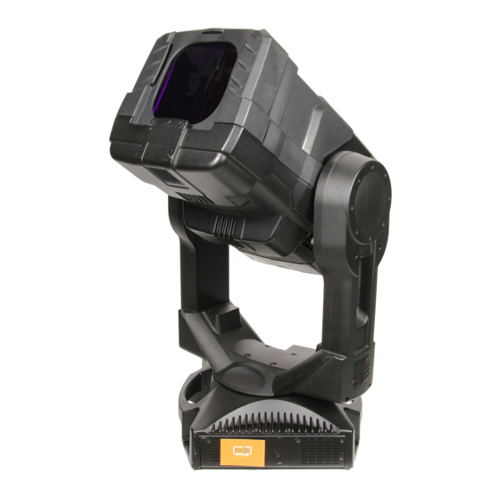
The Source Four Revolution high performance automated ellipsoidal spotlight is intended for professional
use only. Read entire User Manual before using equipment.
© C o p y r i g h t 2 0 0 7 . E le c tr o n i c T h e a t r e C o n t r o l s , I n c .
A l l r i g h t s r e s e r v e d .
P r o d u c t in f o r m a t i on a n d s p e c i f i c a t i o n s s u bj e c t t o c h a n g e .
P a r t N u m b e r : 7160M1200 R e v E
R e l e a s e d : A u g u s t 2 0 0 8
Advertisement
Table of Contents

Related Manuals for ETC Source Four Revolution


Summary of Contents for ETC Source Four Revolution
- Page 1 August 2008 For Revolutions manufactured May, 2007 or after (7160A1017), see Revolution User Manual 7160M1210. The Source Four Revolution high performance automated ellipsoidal spotlight is intended for professional use only. Read entire User Manual before using equipment. © C o p y r i g h t 2 0 0 7 . E le c tr o n i c T h e a t r e C o n t r o l s , I n c .
- Page 2 A C C R E D I T A T I O N S A N D R E C O G N I T I O N S ( f r o m E T L S E M K O : w w w .u s a .
-
Page 3: Table Of Contents
T a b l e o f C o n t e n t s Specifications ....ii Overview ......1 Document Conventions . -
Page 4: Specifications
• Iris Module - for beam size control down to 2.5° M-size glass or metal gobos and filters, indexes with 16-bit accuracy • Shutter Module - four blades with 90° rotation for full- function framing Source Four Revolution User Manual... -
Page 5: Overview
If you have questions about your Source Four Revolution fixture that are not answered in this manual, please contact the supplier of your ETC equipment or ETC Technical Services. -
Page 6: Document Conventions
W A R N I N G : RISK OF ELECTRIC SHOCK! This warning statement indicates situations where there is a risk of electric shock. Source Four Revolution User Manual... -
Page 7: Safety
W A R N I N G : Note the following safety warnings before use: • Do not mount the Source Four Revolution fixture on or near a flammable surface. • Use the fixture in dry locations only, where humidity does not exceed 90 percent (non- condensing). -
Page 8: Installation
(switched) operation. The Source Four Revolution operates on DMX control signal. The unit is supplied with a 5-pin XLR DMX input connector and a 5-pin DMX Thru connector. DMX cables should be acceptable for DMX data transmission (not microphone cable) and should follow the standard pinout. -
Page 9: Installation Procedures
I n s ta l l i n g h a n g i n g h a r d w a r e The Source Four Revolution fixture’s upper enclosure provides six bolt holes for installation of hanging hardware. Suspend the fixture from a suitable structure using a minimum of two hook clamps secured with tightened steel bolts (12 mm (1/2”) Ø), washers and locking nuts. - Page 10 454mm (17.9") 317mm 344mm (12.5") (13.5") 856mm 619mm (33.7") (24.4") 116mm (4.6") 400mm 394mm (15.7") (15.5") Distance between 775mm upper enclosure (30.5") and pipe is variable (hanging hardware dependent). 856mm (33.7") 713mm (28.1") 762mm (30.0") Source Four Revolution User Manual...
- Page 11 S a f e t y C a b l e The safety cable (or other approved safety device) should be secured to one of the handles on the upper enclosure, wrapped around the hanging structure (pipe), then secured to the other handle on the upper enclosure.
-
Page 12: Connections And Addressing
Align and insert the power connector. Twist the connector clockwise until it locks into place. Disconnect the AC Input cable: Slide back the locking tab, twist the connector counterclockwise and pull to unlock and disconnect the power connector. Source Four Revolution User Manual... -
Page 13: Power-Up Procedure And Calibration
Move the power switch/breaker to the “on” position to apply power to the fixture. C A U T I O N : The Source Four Revolution fixture is provided with pan and tilt locks for your convenience when working on the fixture. The pan lock is located on the upper enclosure and the tilt lock is located on the tilt side yoke leg. -
Page 14: Control
C o n t r o l The Source Four Revolution fixture can take as few as 14 and up to 31 DMX channels to operate. The table below describes the order and function of each address, as well as which parameters are affected by the timing channels. -
Page 15: Control Values For The Standard 12-Color Gel String . 11 Reset Channel
C o n t r o l V a l u e s f o r t h e S t a n d a r d 1 2 - C o l o r G e l S t r i n g Percent Percent Percent... -
Page 16: Timing Channels
Revolution parameters. Remember to restore this channel to 0% (or the desired timing speed value less than 100%) for smoothest cue playback operation. N o t e : Playback of cues with the Focus Channel set at 100% may result in less than satisfactory luminaire movement. Source Four Revolution User Manual... -
Page 17: Configuration
Configuration With Source Four Revolution, you decide how to configure your light. The standard base unit provides pan, tilt, beam-edge change, 15-35° zoom range, two Blank Modules, Internal Media Frame, integrated color scrolling, and on-board dimming. The unit’s module bays can be filled with any of the modules described below. -
Page 18: Removing And Replacing Modules
Shutter Modules must be placed only in the rear bay. Shutter module installation also must include mounting the counterweight frame that came with the revolution in the front of the unit. See Shutter Module (SM), page Source Four Revolution User Manual... -
Page 19: Blank Module (Bm)
Front Bay Rear Bay Blank Module (BM) The Blank Module is used to fill an empty module bay, and can be used to hold a static M-Size metal gobo, if needed. M-Size metal gobos only. Pull gently to remove and insert metal gobos. Configuration... -
Page 20: Iris Module (Im)
Iris Module (IM) The Iris Module contains an 18-leaf iris and can be placed in either module bay. Source Four Revolution User Manual... -
Page 21: Shutter Module (Sm)
Shutter Module (SM) The Shutter Module contains a four-blade shutter mechanism. Each shutter can be rotated +/– 45° (total range of motion = 90°). C A U T I O N : The Shutter Module must be placed in the Rear Bay. It will not operate in the Front Bay. -
Page 22: Static Wheel Module (Swm)
Use the table below to set the Wheel Position channel. Wheel Position Channel DMX Percent DMX Decimal Open (Position 0) 0-5% 0-13 Position 1 6-10% 14-26 Position 2 11-15% 27-39 Position 3 16-20% 40-50 Reserved (Position 3) 21-100% 51-255 Source Four Revolution User Manual... -
Page 23: Rotating Wheel Module (Rwm)
Rotating Wheel Modul e (RWM) The Rotating Wheel Module contains a wheel with three rotating/indexing positions for static M-size steel or glass gobos or dichroic color filters and an open position. C A U T I O N : To prevent cracking of glass gobos and for best image contrast, the silver reflective surface of the gobo must face the lamp and the black surface of the gobo must face the lenses. -
Page 24: Controlling The Rotating Wheel Module
16-100% 40-255 Wheel Index/Rotation Channel DMX Percent DMX Decimal If Indexing, use this 16-bit channel to align the 0-100% 0-255 image If Rotating, use this 16-bit channel to set rotation 0-100% 0-255 speed (0-30 RPM) Source Four Revolution User Manual... -
Page 25: Replacing Gobos And Filters
Replacing Gobos and Fil ters The Static Wheel Module and the Rotating Wheel Module both use the same gobo/filter retention method. In each case, the gobo/filter is secured with a spring. Replace a gobo/filter: Step 1: Power-down the fixture. See Power-down Procedure, page Step 2: Remove the module from the fixture. - Page 26 Step 7: Reinsert the module into the fixture and tighten the screws securing the module. Spring Rotating Wheel Alignment Hole M-Size Gobo Static Wheel Alignment Hole Static Wheel Frame DETAIL: gobo installed Source Four Revolution User Manual...
-
Page 27: Routine Maintenance
Routine Maintenance To ensure optimum performance of your Source Four Revolution fixture, you should perform the following inspections and cleanings at least once a year. You may need to inspect or clean the fixture more often, depending on the type and amount of use your fixture experiences during the year. -
Page 28: Procedures
S c r o l l e r C a r t r i d g e s a n d B e a m C o n t a i n m e n t D e v i c e s The Source Four Revolution fixture is provided with a removable scroller cartridge. You can swap whole cartridges, or you can replace only the gel string within the cartridge. -
Page 29: Gel Strings
Installing or removing beam containment devices and color frames: Step 1: Push the latch on top of the scroller cartridge toward the back of the fixture head to clear the accessory slot on the front of the cartridge. Step 2: Insert or remove the beam containment device or color frame. - Page 30 Step 10: When the leader is attached to the left spool, let go of the spools. The gel scroll should spool a number of frames onto the left spool and then settle. Step 11: Reset the fixture to calibrate and ensure proper performance of the scroller. Source Four Revolution User Manual...
-
Page 31: Internal Media Frame (Imf)
I n t e r n a l M e d i a F r a m e ( I M F ) The internal media frame is designed to hold two pieces of gel within two semi-circular removable frames. Performance of the gel in the internal media frame will vary with frequency of use, materials and transmission properties of the gel. - Page 32 If the pawl does not close completely so that it does not engage the IMF doors, move the clip toward the rear of the fixture. Source Four Revolution User Manual...
- Page 33 N o t e : If the spring clip does not allow enough movement, move the spring to the next notch in the clip. Step 7: When the pawl operates fairly quietly, tighten the spring tension clip screw. Step 8: Adjust the other pawl if needed.
-
Page 34: Changing And Adjusting The Lamp
W A R N I N G : RISK OF ELECTRIC SHOCK! Do not place objects other than a QXL lamp in the Source Four Revolution lamp socket. C A U T I O N : Do not touch the glass envelope of the QXL lamp. Oils and residue left on the envelope can cause premature failure of the lamp. - Page 35 Adjusting the lamp: Step 1: Apply power to the fixture and allow it to complete its calibration. Step 2: Bring intensity to full and aim the fixture at a flat surface. Step 3: Unlock and loosen the outer lamp adjust knob by turning it counter-clockwise. Step 4: Gently move the outer lamp adjust knob from side to side and up and down until the lamp is centered in the reflector.
-
Page 36: Adjusting Belt Tensions
Make sure the spring is centered on the plate. Step 5: Tighten the motor screws in a star pattern. Step 6: Place the yoke cover back on and tighten the captured screws. Belt Tension Spring Tilt Lock Mechanism Motor Adjustment Screws Source Four Revolution User Manual... - Page 37 Adjusting pan belt tension: Step 1: Power-down the fixture (see Power-down Procedure, page 9) and disconnect any power and data cables from the upper enclosure. Step 2: Place the fixture on its side on a stable surface. Step 3: Remove any hook or hanging hardware from the data module side of the upper enclosure and loosen the two rubber feet on that side.
- Page 38 Remove the head cover by loosening, but do not remove, the two captured screws holding it in place and lift the cover off the head. Front Lens Motor Front Lens Rear Lens Motor Scroller Motor Source Four Revolution User Manual...
- Page 39 Motor Pulley Motor Adjustment Screws Belt Tension Adjusting the scroller drive belt tension: Step 1: General belt adjustment instructions:, page Step 2: Remove the scroller if not already done. See Removing and replacing the Scroller Cartridge:, page Step 3: Using both hands, gently fold in the IMF doors and move the assembly toward the rear lens.
- Page 40 There should be a slight resistance. Continue turning to open the IMF. Step 9: Turn the motor by hand clockwise to move the lens back. If the IMF does not close properly, readjust the front lens belt so that it is tighter. Source Four Revolution User Manual...
- Page 41 Belt Tension Motor Adjustment Screws. Motor Adjusting rear lens belt: Step 1: General belt adjustment instructions:, page Step 2: Using both hands, gently move the IMF assembly forward toward the front lens so that you can access the rear lens motor. Step 3: Loosen, but do not remove, the two motor mounting screws so that the motor moves freely.
-
Page 42: Troubleshooting
L E D I n d i c a t o r s The easiest way to find out the status of your Source Four Revolution fixture is to look at the LED indicators on the upper enclosure. These LEDs are located on the top of the upper enclosure when the fixture is sitting on its base. -
Page 43: Internal Test Software
I n t e r n a l T e s t S o f t w a r e The following diagnostic tests are available using the thumbwheels on your Source Four Revolution fixture. To run a test, set the address to the desired test (tests may be run at any time). - Page 44 Source Four Revolution User Manual...
- Page 45 Routine Maintenance...
- Page 46 Source Four Revolution User Manual...
-
Page 47: Photometric Data
Photometric Data M i n i m u m S p r e a d Throw Distance (d) 400K 37.2ft 44.7ft 52.1ft 59.6ft 11.3m 13.6m 15.9m 18.2m 300K 15.3˚ 10.5˚ 1/2 Peak 1/10 Peak 200K 100K 1/10 Peak Diameter 10ft 12ft 14ft 16ft... - Page 48 Corporate Headquarters 3031 Pleasant View Road, P.O. Box 620979, Middleton, Wisconsin 53562-0979 USA Tel +608 831 4116 Fax +608 836 1736 London, UK Unit 26-28, Victoria Industrial Estate, Victoria Road, London W3 6UU, UK Tel +44 (0)20 8896 1000 Fax +44 (0)20 8896 2000 Rome, IT Via Ennio Quirino Visconti, 11, 00193 Rome, Italy Tel +39 (06) 32 111 683 Fax +39 (06) 32 656 990 Holzkirchen, DE Ohmstrasse 3, 83607 Holzkirchen, Germany Tel +49 (80 24) 47 00-0 Fax +49 (80 24) 47 00-3 00 Hong Kong Rm 1801, 18/F, Tower 1 Phase 1, Enterprise Square, 9 Sheung Yuet Road, Kowloon Bay, Kowloon, Hong Kong Tel +852 2799 1220 Fax +852 2799 9325...
Need help?
Do you have a question about the Source Four Revolution and is the answer not in the manual?
Questions and answers