Table of Contents
Advertisement
Quick Links
Advertisement
Table of Contents

Subscribe to Our Youtube Channel
Related Manuals for ETC HIGH END SYSTEMS SolaPix 37


Summary of Contents for ETC HIGH END SYSTEMS SolaPix 37
- Page 1 Automated Luminaire User Manual Version 1.1 — Revision A...
- Page 2 To view a list of ETC trademarks and patents, go to etcconnect.com/ip. To view a list of High End Systems, Inc. patents, go to highend.com/patents. All other trademarks, both marked and not marked, are the property of their respective owners.
-
Page 3: Table Of Contents
Table of Contents Introduction Contacting High End Systems Headquarters Technical Support FCC Information Patents Terms and Conditions and Warranty Information Product Modification Warning Mise En Garde Contre La Modification Du Produit Produktmodifikationswarnung Avvertenza Sulla Modifica Del Prodotto Advertencia De Modificatión Del Producto Important Safety Information Fixture Overview Modular Control... - Page 4 DMX Control DMX Connector Pinout Connect DMX Cables to Fixture Terminate DMX Set the DMX Start Address DMX Channels Ethernet Control Connect Ethernet Cables to a Fixture Set the DMX Start Address Set the Control Source and Universe Configure the Fixture Navigate the User Interface Set Fixture Parameters Address Info Menu...
-
Page 5: Introduction
SolaPix 37 fixture. Contacting High End Systems High End Systems, Inc. is an ETC company. Headquarters For Customer Service or Sales support, please contact our company headquarters: 2105 Gracy Farms Lane Austin, TX 78758 USA Tel: 512.836.2242... -
Page 6: Terms And Conditions And Warranty Information
Terms and Conditions and Warranty Information Complete terms and conditions and warranty information can be found on the High End Systems, Inc. website: highend.com/pub/products/HES-Warranty-Information.pdf. Product Modification Warning High End Systems products are designed and manufactured to meet the requirements of the United States and International safety regulations. -
Page 7: Important Safety Information
Important Safety Information Please read all instructions prior to assembling, mounting, and operating this equipment. Continued and safe operation of this fixture is the responsibility of the operator. This manual will give tips for that continued safe operation. At any time please contact High End Systems Technical Support for any safety concerns. -
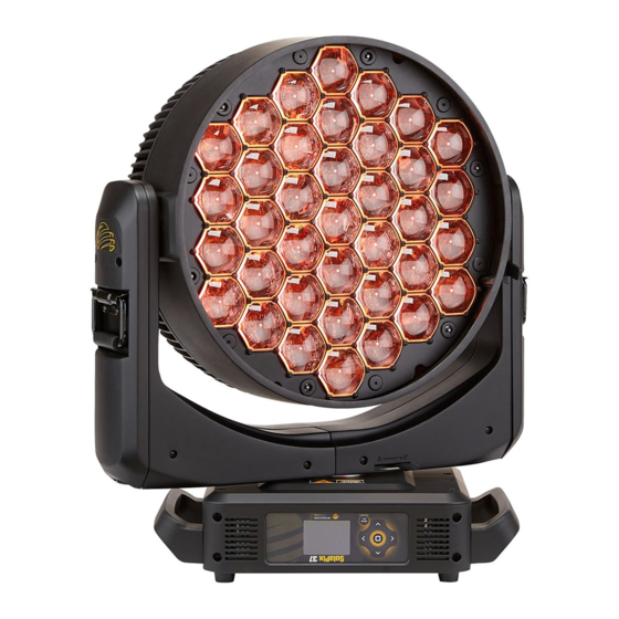
Page 8: Fixture Overview
Fixture Overview For technical specifications of the SolaPix 37 fixture, see the technical data sheet: highend.com/documentation/SolaPix37/SolaPix37-Datasheet.pdf 1: Lens 2: Tilt lock 3: Display 4: Navigation controls 5: Pan lock 6: Handle 7: Power In 8: USB 9: DMX In 10: DMX Thru 11: Ethernet ports (x2) 9 10 11 SolaPix 37 User Manual... -
Page 9: Modular Control
Modular Control Note: Some consoles may refer to the Flex effects by the feature name "Macro". For the purposes of the SolaPix 37 software and user manual, "Flex" and "Macro" are interchangeable. The SolaPix 37 fixture has three segments of control (or modules) that essentially give you three fixtures in one, letting you customize each fixture based on your control needs. -
Page 10: Dimensions
Dimensions Dimensions shown are listed as inches [millimeters]. 7.3" [186mm] 4.0" 3.3" [85mm] [101mm] 24.2" [614mm] 19.5" 18.1" [494mm] 16.1" [460mm] [409mm] 19.9" 10.4" 4.9" [265mm] [505mm] [125mm] 7.1" [180mm] 7.1" [180mm] 21.0" [533mm] SolaPix 37 User Manual... -
Page 11: Safety Considerations
Safety Considerations In order to ensure safe operation, follow the safety instructions and warning notes in this user manual and any instructions from the manufacturer representative. The SolaPix 37 fixture is intended for professional use only. Not for residential use. Read •... -
Page 12: General Operation And Use Guidelines
• other persons who are not qualified and familiar with its functions to operate the fixture. Please use the original packaging if the fixture is to be transported. ETC and High End • Systems, Inc. will not be responsible for the fixture if packaging other than manufacturer provided packaging is used. -
Page 13: Install The Fixture
Install the Fixture WARNING: The installation location must support a minimum point load of 10 • times the weight of the fixture. The installation must always be secured with a secondary safety • attachment. An appropriate safety cable is supplied. Safety cable attachment must be rated by a safety factor of 10. - Page 14 Assemble the clamp (provided by others) to the Omega bracket and secure together using appropriately sized hardware (not provided). Align the assembled Omega bracket and quick-lock fasteners into the respective holes on the bottom of the fixture upper enclosure. Tighten each of the quick-lock fasteners fully, turning clockwise. You will hear and feel a click when the fastener is fully secured.
-
Page 15: Power
Power Input and Power Factor Amps Watts 19.4 1891 1938 0.99 15.2 1815 1822 0.99 1710 1723 0.99 1716 1730 0.99 1704 1721 0.98 1704 1726 0.98 Connector Specification A fixture power cord with powerCON TRUE1 TOP input to bare end is provided. Install a suitable connector to meet the installation requirements. -
Page 16: Dmx Control
DMX Control The SolaPix 37 fixture operates on standard DMX-512 control bus, controlled by a DMX console. The fixture requires 186 channels of DMX-512 in standard mode. Two XLR termination receptacles are available: one for connection of DMX Input, and one for DMX ... -
Page 17: Terminate Dmx
Terminate DMX Use a DMX terminator or install a resistor on the last fixture of the DMX control run to prevent corruption (data reflection) of the digital control signal by electrical noise. A DMX terminator is an XLR plug with a 120 Ω resistor connected between pins 2 and 3 that can be installed into the DMX output receptacle of the last fixture in the DMX control run. -
Page 18: Ethernet Control
Ethernet Control The SolaPix 37 fixture includes two Ethernet ports that allow sending and receiving of control signals using the Art-Net protocol or sACN. Use a Cat5e (or better) cable and terminate to RJ45 connectors following the TIA/EIA 568B wiring standard. Connect Ethernet Cables to a Fixture The following instructions are guidelines for connecting Ethernet to your fixture. -
Page 19: Set The Dmx Start Address
Set the DMX Start Address Give each fixture a unique DMX starting address so that the correct fixture responds to the control signals. This DMX start address is the channel number from which the fixture starts to “listen” to the digital control information sent out from the control source. Example: The SolaPix 37 requires up to 186 channels of control depending on the configuration of the modules. -
Page 20: Configure The Fixture
Configure the Fixture You can configure SolaPix 37 fixtures through the onboard user interface. Navigate the User Interface Mode Esc. Mode Press the [MODE/ESC] button to access the main menu. (The display is powered by Esc. Mode battery when the fixture has no power; press and hold the [MODE/ESC] button Esc. -
Page 21: Set Fixture Parameters
Set Fixture Parameters This section provides instructions to configure and set up the SolaPix 37. See Navigate the User Interface on the previous page for information about the navigation buttons. Provide power to the fixture before configuring it. If you do not provide power, the fixture will use battery power to power the user interface. - Page 22 Navigate: Main Menu → Address → Flex Module The Flex module is an optional feature. Select Disable in the Mode menu to turn off the module. Settings Value Description Select how the Flex module is implemented: Compound - the module inherits its settings from •...
- Page 23 Navigate: Main Menu → Address → Pixel Module The Pixel module is an optional feature. Select Disable in the Mode menu to turn off the module. Settings Value Description Select how the Pixel module is implemented: Compound - the module inherits its settings from •...
- Page 24 Example Use Cases Default Use Case The system has a small number of fixtures and limited universes of DMX, so numerous channels of DMX cannot be dedicated to each individual fixture. Example: For each fixture: Configure the Base module with DMX source and a unique address. •...
-
Page 25: Info Menu
Separate Console Control and Video Server Control The system contains a video control source in addition to a DMX console. Example: For each fixture: Configure the Base module with DMX source and a unique address. • Set the Flex module to Compound mode. •... - Page 26 View the DMX value of each of the fixture's channels (parameters of the fixture). Scroll to the parameter that you want to view (Pan, Tilt, etc.) and view the value. The DMX value that you view is the DMX value that displays on the main window of the UI until you select a different DMX value to view.
-
Page 27: Set Menu
Set Menu Set the Status Options Navigate: Main Menu → Set → Status Parameter Value Description Close Shutter • Control mode when DMX is absent. The default value No DMX Mode Hold • is Hold. Auto Program • Reverse the pan movement of the fixture. The default •... - Page 28 Access Service Settings Navigate: Main Menu → Set → Service Setting Parameter Value Description You must enter the Service PIN in order to access the Service PIN Service PIN XXX other Service Setting parameters. The default Service PIN is 050. This password-protected menu item lets you modify the RDM UID.
- Page 29 Set Display Settings Navigate: Main Menu → Set → Disp. Setting Parameter Value Description Enter the amount of time the fixture waits after the Shutoff Time 02–60 minutes last user interface button press until the display goes to sleep. The default value is 5 minutes. Flip the display 180°...
-
Page 30: Test Menu
Test Menu Reset (Home) the Mechanical Positions on the Fixture Navigate: Main Menu → Test → Home Reset ("home") all features on the fixture, including, pan, tilt, colors, gobos, etc. Test the Fixture Navigate: Main Menu → Test → Self Test Run a self-test program on the fixture. When you run the test, the display indicates "Running"... -
Page 31: Preset Menu
Select an Auto Program above fixture (see Navigate to the Auto Program that you want to edit (Program 1, Program 2, etc.), and then set the scene (SC001, SC002, etc.) for each step (Step 01, Step 02, etc.) in the Auto Program. You can set a maximum of 64 steps. - Page 32 Auto Program. Each scene is a snapshot of a set of fixture parameters (for example, color, beam quality and pattern, intensity, focus, etc.) that you can assign to a step in an Auto Program. Select the scene (Scene 001, Scene 002, etc.) that you want to edit, and then set the parameters for the scene or capture the parameters for the scene from the current DMX input.
-
Page 33: Error Codes
Error Codes When you apply power to the fixture, it runs a calibration (homing) sequence and displays any errors that it detects. Example: When the display shows "Error channel: Pan Coarse", it means there is an error in channel 1. When multiple errors are present they will cycle on the display twice, and then the fixture will reset (restart). -
Page 34: Cleaning And Maintenance
Cleaning and Maintenance WARNING: Disconnect the fixture from mains power before starting any maintenance procedures. Keep the following in mind during regular service and inspection: All screws for installing the fixture or parts of the fixture must be tightly connected and •... - Page 35 Cleaning and Maintenance...
- Page 36 Support support.etcconnect.com/HES © 2020 Electronic Theatre Controls, Inc. n Product information and specifications subject to change. ETC intends this document to be provided in its entirety. n Trademark and patent info: etcconnect.com/ip SolaPix 37 User Manual Rev A Released 2020-04...
Need help?
Do you have a question about the HIGH END SYSTEMS SolaPix 37 and is the answer not in the manual?
Questions and answers