Table of Contents
Advertisement
Quick Links
Download this manual
See also:
Instruction Manual
M ULT IM EDI A A UDIO A ND V I SU A L
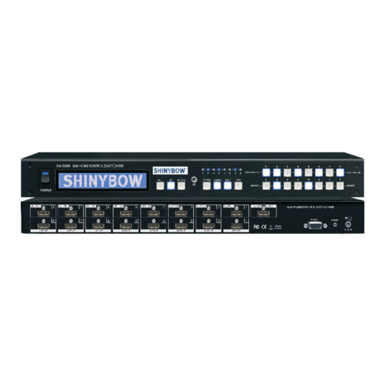
8x8 HDMI MATRIX SWITCHER
INSTRUCTION MANUAL
MODEL : SB-5688
8X8 HDMI MATRIX SWITCHER
HDMI Matrix Switcher Series
Thank you for purchasing the SB-5688 HDMI Matrix Switcher. You will find this unit easy to install and highly
reliable but it is essential that you read this manual thoroughly before attempting to use 8x8 HDMI Matrix switcher.
Part No.: ENCL005688000A2
Advertisement
Table of Contents

Subscribe to Our Youtube Channel
Related Manuals for Shinybow USA SB-5688


Summary of Contents for Shinybow USA SB-5688
- Page 1 HDMI Matrix Switcher Series Thank you for purchasing the SB-5688 HDMI Matrix Switcher. You will find this unit easy to install and highly reliable but it is essential that you read this manual thoroughly before attempting to use 8x8 HDMI Matrix switcher.
-
Page 2: Safety Information
SAFETY INFORMATION Save the carton and packing material even if the equipment has arrived in good condition. Should you ever need to ship the unit, use only the original factory packing. Read all documentation before operating your equipment. Retain all documentation for future reference. Follow all instructions printed on unit chassis for proper operation. -
Page 3: Table Of Contents
(7) different modes. Control is provided via Front panel push buttons, IR remote or via RS-232. An RS-232 Windows GUI interface is provided for matrix routing. The SB-5688 is a 8x8 HDMI Matrix Switcher featuring 8 inputs and pre-emphasized 8 outputs. Full support HDMI / HDCP compliant. 8 inputs as following : 8 matrix outputs as following : • 8 x HDMI (Digital Video/Audio) -
Page 4: Features And Specifications
FEATURES & SPECIFICATIONS FEATURES 1. Support 8x HDMI digital source devices matrix switched to 8x HDMI devices. 2. HDMI digital video w/embedded audio, DVI format and HDCP compliant 3. Seven (7) function key control and worldwide EDID modes for HDTV resolutions. 4. -
Page 5: Edid Functions
EDID FUNCTION EDID function for HDMI Matrix Switcher EDID Status To view the current EDID status Step 1 . Press EDID button The button will flash blue and the display will show the current EDID Status. Step 2 . Press EDID button to exit. EDID Setup To change the EDID setup The button will flash blue and the display will show Step 1 . - Page 6 CONSUMER ELECTRONICS CONTROL (CEC) CONSUMER ELECTRONIC CONTROL (CEC) In brief, CEC allows HDMI devices to control each other when necessary and allows the user to operate multiple devices with one remote control handset. To Enable CEC - Press EDID button - Press ALL button - Press EDID button The pre-set configuration will execute.
-
Page 7: Front Panel
FRONT PANEL FRONT PANEL POWER SWITCH The power switch turns the unit on and off. The LED will illuminate red to indicate that the switcher is ON and is receiving power. The Switcher will remember that last state during a power cycle. When power is removed and resorted, the last configuration will be evoked. INPUT STATUS DISPLAY Input sources 1 to 8 LED illuminates blue to indicate that a video source is present on that input. OUTPUT STATUS DISPLAY Each Output (destination) Channel shows which input (source) is assigned. - Page 8 FRONT PANEL FRONT PANEL FUNCTION KEY - OFF Disables (mute) video to selected channels. Either destinations. - Press OFF button followed by any Destination channel. - Press 1 thru 8 output destination. The display will show “ 0 “ for the selected channel indicating no video selected. FUNCTION KEY - PREV The system will show previously stored presets, up to a total of 16.
-
Page 9: Rear Panel
REAR PANEL REAR PANEL DC POWER INLET Power Jack: The Switcher is fitted with a DC power plug input connector. DC Jack - Inner OD O 2.1mm (+ ) Ensure that the used is of an approved type and is of sufficient Outside OD O 5.5mm (GND) current carrying connector capacity with the correct voltage and Power input - 12VDC, 2A connector polarity. 12Volt DC power supply 4A Max (Center pin positive). IR EXTENDER CONTROL IR Extender Jack: Support one of IR Extender... -
Page 10: Typical Application
3. HDMI (HDCP Compliant) 7. HDMI (HDCP Compliant) 4. HDMI (HDCP Compliant) 8. HDMI (HDCP Compliant) DC POWER INPUT : SUPPORT DC12V POWER INPUT SB-5688 SUPPORT EIGHT HDMI INPUTS TO EIGHT HDMI MATRIX OUTPUTS SUPPORT IR EXTENDER & RS-232 CONTROLS. -
Page 11: Remote Control
REMOTE CONTROL Before making any connections to the switcher. Observe the following: > Ensure the mains voltage supply matches the label on the > Connect all audio video sources and destination equipment supplied plug-pack (+/- 10%) > Power up all source and destination audio-visual sources >... -
Page 12: Ir Extender
IR EXTENDER REAR PANEL IR EXTENDER PORT *** When you plug the External IR extender into the switcher, the front panel IR receiver remains active. *** IR EXTENDER PACKAGE : HOW TO SETUP THE IR EXTENDER COMPONENTS... -
Page 13: Rs-232 Serial Interface
RS-232 SERIAL INTERFACE RS-232 SERIAL INTERFACE CONNECT a PC or CONTROL SYSTEM. VERSION-1.0 COMPATIBLE RS-232 SERIAL INTERFACE RS-232 Definition -------- Not used Transmitter Receiver -------- Not used Ground -------- Not used -------- Not used -------- Not used -------- Not used RS-232 The SHINYBOWUSA switcher can be controlled via the RS-232 serial control port to allow for interfacing to a PC, or similar third party control system. -
Page 14: Rs-232 Serial Commands
RS-232 SERIAL COMMANDS MORE STUFF Note: Turning the unit System Power Off via RS-232 will extinguish the LED channel display leaving only the Power Switch LED on. The Video and Audio outputs will also mute. While the unit is turned off by RS-232 it will continue to accept and act upon switching commands. -
Page 15: Limited Warranty
LIMITED WARRANTY LIMITED WARRANTY SHINYBOWUSA WARRANTY SHINYBOWUSA Technology warrants this product against defects in materials and workman ship for a period of 3 year from the date of purchase. Should this product, in SHINYBOWUSA Technology’s opinion, Prove defective within this warranty period, SHINYBOWUSA Technology, at its option, will repair this product without charge, to whatever extent it shall deem necessary to restore said product to proper operation condition. - Page 16 MU LT I MEDI A AUDIO AN D VIS UAL www.shinybowusa.com 1399 Wildfire Lane | Frisco, TX 75034 1-877-SHINY-USA 1-877-744-6987 1-972-377-2508 sales@shinybowusa.com...
Need help?
Do you have a question about the SB-5688 and is the answer not in the manual?
Questions and answers