Table of Contents
Advertisement
Quick Links
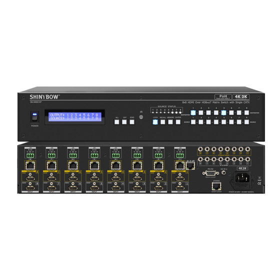
SB-5688CKP
8x HDMI Inputs / 8x HDMI & 8x HDBaseT
PoH Outputs - UHD 4K2K
™
Matrix Routing Switch w/ EDID
IMPORTANT WARRANTY INFORMATION.
If you remove the HDMI screw posts, you must use the provided HDMI Locking Post
replacement screws to keep the internal HDMI jack secure. Removing the HDMI screws
without installing the HDMI Locking Post replacement screws will void your warranty.
Advertisement
Table of Contents

Subscribe to Our Youtube Channel
Related Manuals for Shinybow USA SB-5688CKP


Summary of Contents for Shinybow USA SB-5688CKP
- Page 1 SB-5688CKP 8x HDMI Inputs / 8x HDMI & 8x HDBaseT PoH Outputs - UHD 4K2K ™ Matrix Routing Switch w/ EDID IMPORTANT WARRANTY INFORMATION. If you remove the HDMI screw posts, you must use the provided HDMI Locking Post replacement screws to keep the internal HDMI jack secure. Removing the HDMI screws...
- Page 2 SAFETY INFORMATION To ensure the best results from this product, please read this manual and all other documentation before operating your equipment. Retain all documentation for future reference. Follow all instructions printed on unit chassis for proper operation. To reduce the risk of fire, do not spill water or other liquids into or on the unit, or operate the unit while standing in liquid. Make sure power outlets conform to the power requirements listed on the back of the unit.
-
Page 3: Table Of Contents
Check that you have the following components; sufficient space for air to circulate around the unit. • SB-5688CKP Matrix Switcher (Power Over HDBaseT ™ • RS-232 V2.0 / Ethernet V1.0 Protocol Instructions DISCLAIMERS •... -
Page 4: Introduction
INTRODUCTION & FEATURES INTRODUCTION The SB-5688CKP is a professional 8x8 matrix routing switch with PoH, supporting (8) HDMI and (8) Auxiliary Audio Inputs and (8) HDMI, (8) SPDIF and (8) HDBaseT (PoH) Outputs. The SB-5688CKP is based on HDBaseT standards and supports full resolution HDMI video ™... -
Page 5: Specifications
SPECIFICATIONS SPECIFICATIONS • Type of HDMI Switcher: (8) Inputs to (8) Outputs HDMI over HDBaseT Matrix Switch with Audio and Extension ™ • HDMI Support: HDMI 4K2K@30Hz, 1080p@60Hz, H36-bit Deep color, 3D of HDMI V1.4 formats • HDBaseT Support: Bi-directional IR, RS-232, Multi Format Audio, Ethernet and PoH over a category cable ™... -
Page 6: Front Panel
FRONT PANEL FRONT PANEL 1. POWER ON SWITCH: The power switch turns the unit on and off. The LCM will illuminate blue to indicate the switcher is ON and receiving power. The switcher will remember the last setting during a power cycle. When power is removed and resorted, the last configuration will be evoked. - Page 7 FRONT PANEL-EDID FRONT PANEL-EDID 9. FUNCTION KEY - EDID (1): Used to display changes/current EDID mode. - Press EDID to select new EDID mode - Press SOURCE row #1 or #2 to select EDID modes. - Press ENTER to ready memory location. - Or press EDID again to cancel the operation.
- Page 8 FRONT PANEL-ALL-LOCK-ENTER FRONT PANEL-ALL-OFF-LOCK-ENTER 10. FUNCTION KEY - ALL: Disables (mutes) video on all destinations OR assign the same source to all destinations. Option 1 - Press ALL followed by OFF button. The display will show ”0” to indicate none of the destinations are assigned a video source.
- Page 9 FRONT PANEL-OFF 13. MUTE DESTINATION: Disables (mutes) video to selected channels for either destination. - Press OFF button followed by any Destination channel. Option 2 - Press ALL followed by Source 1 THRU 8. The display will show the source selected. - Press 1 THRU 8 output destination.
- Page 10 FRONT PANEL-RECALL-MEMORY FRONT PANEL-RECALL-MEMORY 14. FUNCTION KEY - RECALL: The system will show previously stored presets, up to a total of (16). Presets are stored in local memory using Source keys 1 thru 8 or Destination keys 1 thru 8 as the memory preset location.
-
Page 11: Back Panel
BACK PANEL-SWITCH CONTROLS BACK PANEL-SWITCH CONTROLS 1. DC POWER INLET: POWER SOCKET: The switcher is fitted with a AC power plug Connector Type: IEC 60320 C13 input connector. Ensure that the plug used is of an approved type and is of sufficient current carrying connector capacity with the correct voltage and connector polarity. - Page 12 BACK PANEL-HDMI INPUT / OUTPUT BACK PANEL-HDMI INPUT / OUTPUT 5. INPUTS- 1,2,3,4,5,6,7, & 8 HDMI: HDMI CONNECTOR: Connects HDMI signal source HDMI Type A SMD 19pin female to the Input. This HDMI port supports HDMI with embedded socket connector audio and DVI with AUX audio sources.
- Page 13 BACK PANEL-HDBASET CONTROLS ™ BACK PANEL-HDBASET CONTROLS ™ 9. HDBaseT RS-232 - 1,2,3,4,5,6,7 & 8 CONNECTION: REMOTE PORT: ™ (8) RS-232 Terminal Block-3pin female socket control ports allow for interfacing to a PC. Controls I/O via the HDBaseT Transmitters up to (8) rooms each via the Terminal ™...
- Page 14 BACK PANEL-HDBASET ™ BACK PANEL-HDBASET ™ 13. OUTPUT - 1,2,3,4,5,6,7 & 8 HDBaseT (Transmitter): HDBASET™ TRANSMITTER CONNECTOR: ™ Sends (8) HDMI and control signals via the switchers (8) HDBaseT (8) RJ-45 Jack 8P8C female socket ™ Transmitters to link (8) external HDBaseT Receivers.
-
Page 15: Remote Control
REMOTE CONTROL Before making any connections observe the following: • Ensure the main voltage supply matches the label on the supplied plug-pack (+/-10%). • Ensure that the power switch is OFF. • Ensure that all system grounds (earth) are connected to a common point. •... - Page 16 REMOTE PROTOCOL COMMANDS IR REMOTE CUSTOM AND DATA CODES (NEC Standard) HOW TO SETUP IR CODES: CUSTOM CODE: 4CB3 POWER ON: 4CB3 A15E ALL: 4CB3 B04F RECALL: 4CB3 B24D POWER OFF: 4CB3 A25D OFF: 4CB3 B14E MEMORY: 4CB3 B44B EDID: 4CB3 B748 LOCK:...
-
Page 17: Room Remote Controls
ROOM REMOTE CONTROLS ROOM REMOTE CONTROL #1 ~ #8 CUSTOM CODE AND DATA CODES IR CUSTOM AND DATA CODES (NEC Standard) PRESS Number To Select SOURCE CUSTOM CODE: 4CB3 IR-01 DATA CODE: IR-02 DATA CODE: IR-03 DATA CODE: SOURCE #1 : 4CB3 11EE SOURCE #1 : 4CB3 21DE SOURCE #1 : 4CB3 31CE SOURCE #2 : 4CB3 12ED... -
Page 18: Edid Functions
EDID FUNCTION - SYSTEM RESET/FACTORY RESET SYSTEM RESET SYSTEM RESET RETURN SWITCH TO FACTORY DEFAULTS RECALL > OFF > ENTER RESET to Factory Default Press 1. Press RECALL button: The LCM will show the current stored presets status. 2. Press OFF button: The LCM will show “SYSTEM RESET” 3. - Page 19 EDID FUNCTION EDID FUNCTION FOR HDMI MATRIX SWITCHER EDID SETUP To Change The EDID Setup Step 1. Press the EDID button The display will show the currently selected EDID mode. Step 2. Press SOURCE #1 OR #2 button row The button will flash blue and the display will show the current Embedded EDID Status. Step 3.
- Page 20 EDID FUNCTION EDID FUNCTION FOR HDMI MATRIX SWITCHER EDID FUNCTION FOR HDMI MATRIX SWITCHER Mode 1. FSS (Fast Speed Start) Fast Speed Start mode shortens the startup time of the switcher. Selecting this ® ® mode does not force the EDID setup to be cancelled. Users may first select one EDID mode from mode 2 to 3, and then select mode 1 for Fast Speed Start ®...
- Page 21 EDID FUNCTION LEARNING EDID SINGLE TO SINGLE Learning Destination #2 EDID To Source #3 Step 1. Press EDID button The button will flash blue and the display will show the current Embedded EDID Status. Step 2. Press the DESTINATION #2 button row Copy the Destination #2 Display EDID.
- Page 22 EDID FUNCTION EDID MULTIPLE LEARNING MODE-2 The MULTIPLE LEARNING MODE-2 feature is part of a firmware update released after JUNE 2014. If you do not see the MULTIPLE LEARNING MODE-2 feature then you do not have the latest firmware. You should contact your place of purchase for availability of a firmware update.
-
Page 23: Applications
INSTALLING DIAGRAM Sample Connection: 1. Using IR External, RS-232 or Ethernet commands to control the SB-5688CKP via PC or SB-100 IR receiver to transmit the SB- 5688CKP’s IR signal. 2. Audio output link ARC from TV return channel, HDMI audio source or mixing Auxiliary audio. - Page 24 APPLICATION - HDBASET I/O & RS-232/LAN/IR CONTROLS ™ INSTALLING DIAGRAM Sample Connection: Using SB-5688CKP’s HDBaseT Transmitter (PoH) and one HDBaseT Receiver (PoH) (SB-6335R5) to control a projector via RS-232, ™ ™ LAN or IR remote signals. NOTE: 1. IR Control Projector Over HDBaseT Extender: SB-5688CKP HDBaseT ™...
- Page 25 CONTROL IR TO ROOM ™ INSTALLING DIAGRAM Sample Connection: Using the SB-5688CKP’s (PoH) HDBaseT Extender Control IR signal to Room #5 via SB-5688CKP’s HDBaseT IR input #5 with IR ™ ™ Receiver (SB-100) and HDBaseT Receiver SB-6335R5 PoH with IR Transmitter (SB-101) to control Room #5 TV Display.
- Page 26 To Room.” From the SB-6335R5 (PoH), the IR Output is connected to the projector. This allows remote operation of the projector from the SB-5688CKP. The IR control for source devices uses the same port number on “IR Source” as the Source device connection. In this example, the Blu-Ray player is connected to Input port #5.
-
Page 27: Ir Extender
IR EXTENDER IR EXTENDER 1. SB-100 IR 300M Receiver Switcher IR EXT. In Cable (3C) IR Receiver (SB-100) Distance: Max.300M IR PN#: SB-XXXX R oHS /95/E C INP UT R S -232 IR E XT. in DC 12V IR Rx RS - 232 IR EXT . -
Page 28: Ethernet / Rs-232 Serial Protocols
ETHERNET & RS-232 SERIAL INTERFACE Example of the commanded string to select Inputs: FUNCTION COMMAND VARIABLES Select source Source xxx; xxx = Input Channel (001=Source1, 002=Source2) COMMAND EXAMPLE RESPONSE DESCRIPTION Source 001; Source 001#ok; Select source number 1 ETHERNET SERIAL INTERFACE CONNECT A PC OR CONTROL SYSTEM VERSION COMPATIBLE V2.0 For a complete list of commands, please reference external document extended Ethernet Protocol Instruction Manual. - Page 29 THIS PAGE IS INTENTIONALLY LEFT BLANK.
- Page 30 THIS PAGE IS INTENTIONALLY LEFT BLANK.
- Page 31 LIMITED WARRANTY PLEASE READ THE FOLLOWING TERMS AND CONDITIONS CAREFULLY BEFORE USING THIS HARDWARE, COMPONENTS AND SOFTWARE PROVIDED BY, THROUGH OR UNDER SHINYBOWUSA, INC (COLLECTIVELY, THE “PRODUCT”). By using installing or using the Product, you unconditionally signify your agreement to these Terms and Conditions. If you do not agree to these Terms and Conditions, do not use the Product and return the Product to SHINYBOWUSA, Inc.
- Page 32 122 Rose Ln. Suite 303 | Frisco, Texas 75034 1-877-SHINY-USA 1-877-744-6987 1-972-377-2508 sales@shinybowusa.com www.shinybowusa.com...
Need help?
Do you have a question about the SB-5688CKP and is the answer not in the manual?
Questions and answers