Table of Contents
Advertisement
Quick Links
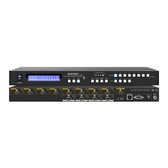
SB-5648K
4x8 HDMI MATRIX SWITCHER
IMPORTANT WARRANTY INFORMATION.
If you remove the HDMI screw posts, you must use the provided HDMI Locking Post
replacement screws to keep the internal HDMI jack secure. Removing the HDMI screws
without installing the HDMI Locking Post replacement screws will void your warranty.
Advertisement
Table of Contents

Related Manuals for Shinybow USA SB-5648K


Summary of Contents for Shinybow USA SB-5648K
- Page 1 SB-5648K 4x8 HDMI MATRIX SWITCHER IMPORTANT WARRANTY INFORMATION. If you remove the HDMI screw posts, you must use the provided HDMI Locking Post replacement screws to keep the internal HDMI jack secure. Removing the HDMI screws without installing the HDMI Locking Post replacement screws will void your warranty.
- Page 2 SAFETY INFORMATION To ensure the best results from this product, please read this manual and all other documentation before operating your equipment. Retain all documentation for future reference. Follow all instructions printed on unit chassis for proper operation. To reduce the risk of fire, do not spill water or other liquids into or on the unit, or operate the unit while standing in liquid. Make sure power outlets conform to the power requirements listed on the back of the unit.
-
Page 3: Table Of Contents
HDMI Matrix Switcher Series Thank you for purchasing the SB-5648K 4x8 HDMI Matrix Switcher. You will find this unit easy to install and highly reliable but it is essential that you read this manual thoroughly before attempting to use 4x8 HDMI Matrix switcher. -
Page 4: Features & Contents
The switcher will remember that last state during a power cycle. When power is removed and resorted, the last configuration will be invoked. PACKAGE CONTENTS Check that you have the following components: • SB-5648K Matrix Switcher • RS-232 V2.0 / Ethernet V1.0 Protocol Instructions • Master Wireless IR Remote Control (SW-5648) •... -
Page 5: Specifications
SPECIFICATIONS SPECIFICATIONS • Type of HDMI Switcher: (4) HDMI Inputs to (8) HDMI Outputs Matrix Switcher • HDMI Supported: HDMI 4K2K@30Hz, H36-bit Deep color, 3D of HDMI V1.4 formats • HDCP / CEC Supported: HDCP 1.3 Compliant, CEC Compliant • Video Bandwidth: Double Data Rates: 340Mhz, total 6.75Gbps bandwidth • Digital Video Supported: Full HD Resolution : 480i / 480p / 720p / 1080i / 1080p • Digital Audio Supported: Multi Audio Formats 5.1 / 7.1, MAT (MLP), Dolby Digital, Dolby TrueHD, Dolby Digital Plus, DTS, DTS-ES 6.1, DTS-HD, DTS-HD-HRA, DTS-HD Master, (PCM-2CH) -
Page 6: Front Panel
FRONT PANEL FRONT PANEL 1. POWER SWITCH: The power switch turns the unit on and off. The LED will illuminate blue to indicate that the switcher is ON and is receiving power. The switcher will remember that last state during a power cycle. When power is removed and resorted, the last configuration will be evoked. - Page 7 FRONT PANEL FRONT PANEL 8. FUNCTION KEY - ALL: Disables (mutes) video on all destinations OR Selects the same source to all destinations. Option 1 - Press ALL followed by the OFF button. The display will show “0“ indicating all destinations have no video selected.
- Page 8 FRONT PANEL FRONT PANEL 12. FUNCTION KEY - MEMORY: The system will show stored presets, up to a total of (12). Presets are stored in local memory using Source keys 1 thru 4 or Destination keys 1 thru 8 as the memory preset location. - Configure desired matrices.
-
Page 9: Back Panel
BACK PANEL BACK PANEL 1. DC POWER INLET: POWER JACK: The switcher is fitted with a DC power plug input connector. Ensure that the plug used is of an approved type DC Jack - Inner OD Ø 2.1mm (+) and is of sufficient current carrying connector capacity with the Outside OD Ø... -
Page 10: Remote Control
REMOTE CONTROL BEFORE MAKING ANY CONNECTIONS OBSERVE THE FOLLOWING: • Ensure the main voltage supply matches the label on the supplied plug-pack (+/-10%). • Ensure that the power switch is OFF. • Ensure that all system grounds (earth) are connected to a common point. •... - Page 11 REMOTE PROTOCOL COMMANDS IR REMOTE CUSTOM AND DATA CODES (NEC Standard) HOW TO SETUP IR CODES : CUSTOM CODE : 1DE2 DATA CODE : POWER ON: 1DE2 A15E LOCK: 1DE2 B54A POWER OFF: 1DE2 A25D RECALL: 1DE2 B24D ALL: 1DE2 B04F MEMORY: 1DE2...
-
Page 12: Rs-232 / Ethernet Serial Interface
RS-232 & ETHERNET SERIAL INTERFACE RS-232 SERIAL INTERFACE CONNECT a PC or CONTROL SYSTEM. VERSION COMPATIBLE V2.0 FFor a complete list of commands, please reference external document extended RS-232 Protocol Instruction Manual. Example of the commanded string to route Input 3 to Output 4 OUTPUT04 03;... -
Page 13: Edid Functions
EDID FUNCTION EDID FUNCTION SETUP EDID SETUP To Change The EDID Setup Step 1. Press the EDID button The display will show the currently selected EDID mode. Step 2. Press SOURCE #1 OR #2 button row The button will flash blue and the display will show the current Embedded EDID Status. Step 3. - Page 14 EDID FUNCTION EDID FUNCTION: (7) EMBEDDED EDID MODES EDID FUNCTION: (7) EMBEDDED EDID MODES Mode 1. FSS (Fast Speed Start Fast Speed Start mode shortens the startup time of the switcher. Selecting ® ® ® this mode does not force the EDID setup to be cancelled. Users may first select one EDID mode from mode 2 to 3, and then select mode 1 for fast speed start ®...
- Page 15 EDID FUNCTION EDID FUNCTION FOR HDMI MATRIX SWITCHER LEARNING EDID Learning EDID From Destination To Source EDID > DESTINATION Learning EDID setup Press Button EDID > DESTINATION > SOURCE > ENTER The LCM will be show LEARNING. The switcher will LEARN destination HDMI Press EDID and pass the selected source.
-
Page 16: Ir Extender
IR EXTENDER IR EXTENDER 1. SB-100 IR 300M Receiver Switcher IR EXT. In Cable (3C) IR Receiver (SB-100) Distance: Max.300M IR PN#: SB-XXXX R oHS /95/E C INP UT R S -232 IR E XT. in DC 12V IR Rx RS - 232 IR EXT . -
Page 17: Typical Application
TYPICAL APPLICATION INSTALLING DIAGRAM Sample Connection: Using RS-232 serial interface or Ethernet TCP/IP to control switch (SB-5648K) and preview output port simultaneously via Output-#1 to extra HDMI HDTV, Display or Monitor. NOTE: 1. IR Control Projector Over HDBaseT Extender: ™... - Page 18 TYPICAL APPLICATION INSTALLING DIAGRAM Sample Connection: Using Audio Extractor (SB-5609) and ARC Control Box (SB-5610) link TV Return Audio to Audio Device, Control a Satellite Receiver source via HDBaseT Transmitter (SB-6335T) and Receiver (SB-6335R). ™ NOTE: 1. IR Control Satellite Receiver Over HDBaseT CAT5e/6/7 ™...
- Page 19 LIMITED WARRANTY PLEASE READ THE FOLLOWING TERMS AND CONDITIONS CAREFULLY BEFORE USING THIS HARDWARE, COMPONENTS AND SOFTWARE PROVIDED BY, THROUGH OR UNDER SHINYBOWUSA, INC (COLLECTIVELY, THE “PRODUCT”). By using installing or using the Product, you unconditionally signify your agreement to these Terms and Conditions. If you do not agree to these Terms and Conditions, do not use the Product and return the Product to SHINYBOWUSA, Inc.
- Page 20 122 Rose Ln. Suite 303 | Frisco, Texas 75034 1-877-SHINY-USA 1-877-744-6987 1-972-377-2508 sales@shinybowusa.com www.shinybowusa.com...
Need help?
Do you have a question about the SB-5648K and is the answer not in the manual?
Questions and answers