Table of Contents
Advertisement
Quick Links
For Quick
Start Installation
CopperLink Model 1314R
Ruggedized Long Range
Ethernet Extender
User Manual
Important
This is a Class A device and is intended for use in a light industrial environment. It is not intended nor approved for use in an industrial
or residential environment.
REGULATORY MODEL NUMBER: 03340D4-001
Sales Office:
+1 (301) 975-1000
Technical Support:
+1 (301) 975-1007
E-mail:
support@patton.com
WWW:
www.patton.com
Part Number: 07MCL1314R, Rev. A
Revised: July 12, 2012
Advertisement
Table of Contents

Related Manuals for Patton CopperLink 1314R


Summary of Contents for Patton CopperLink 1314R
-
Page 1: Copperlink Model 1314R
This is a Class A device and is intended for use in a light industrial environment. It is not intended nor approved for use in an industrial or residential environment. REGULATORY MODEL NUMBER: 03340D4-001 Sales Office: +1 (301) 975-1000 Technical Support: +1 (301) 975-1007 E-mail: support@patton.com WWW: www.patton.com Part Number: 07MCL1314R, Rev. A Revised: July 12, 2012... - Page 2 Patton Electronics specifically disclaims all other warranties, expressed or implied, and the installation or use of this product shall be deemed an acceptance of these terms by the user.
-
Page 3: Summary Table Of Contents
General information ............................13 2 Configuration..............................16 CopperLink installation ..........................24 Operation ..............................28 Software Upgrade ............................30 Contacting Patton for assistance ........................32 Compliance information ..........................35 Specifications ..............................37 Factory replacement parts and accessories ....................41 Interface pinouts... -
Page 4: Table Of Contents
Table of Contents Summary Table of Contents ........................... 3 Table of Contents ............................4 List of Figures ..............................7 List of Tables ..............................8 About this guide ............................. 9 Audience................................. 9 Structure................................. 9 Precautions ................................10 Safety when working with electricity .......................11 General observations ............................12... - Page 5 Contacting Patton for assistance ........................32 Introduction ................................33 Contact information..............................33 Patton support headquarters in the USA ......................33 Alternate Patton support for Europe, Middle East, and Africa (EMEA) ............33 Warranty Service and Returned Merchandise Authorizations (RMAs)..............33 Warranty coverage ............................33 Out-of-warranty service ..........................34 Returns for credit ............................34...
- Page 6 CopperLink Model 1314R User Manual Table of Contents Factory replacement parts and accessories ......................42 Interface pinouts ............................43 Line port ................................44 Ethernet port.................................44...
-
Page 7: List Of Figures
List of Figures CopperLink Model 1314R ..............14 Terminal block power connection . -
Page 8: List Of Tables
List of Tables General conventions ..............12 CopperLink configurable parameters . -
Page 9: About This Guide
About this guide This guide describes installing and operating the Patton Electronics CopperLink™ Model 1314R Ruggedized Long Range Ethernet Extender. Audience This guide is intended for the following users: • Operators • Installers • Maintenance technicians Structure This guide contains the following chapters and appendices: •... -
Page 10: Precautions
CopperLink Model 1314R User Manual Precautions Notes, cautions, and warnings, which have the following meanings, are used throughout this guide to help you become aware of potential problems. Warnings are intended to prevent safety hazards that could result in per- sonal injury. -
Page 11: Safety When Working With Electricity
CopperLink Model 1314R User Manual Safety when working with electricity • Do not open the device when the power cord is connected. For systems without a power switch and without an external power adapter, line volt- ages are present within the device when the power cord is connected. WARNING For devices with an external power adapter, the power adapter shall be a •... -
Page 12: General Observations
CopperLink Model 1314R User Manual Electrostatic Discharge (ESD) can damage equipment and impair electrical circuitry. It occurs when electronic printed circuit cards are improperly handled and can result in complete or intermittent CAUTION failures. Do the following to prevent ESD: Always follow ESD prevention procedures when removing and •... -
Page 13: General Information
Chapter 1 General information Chapter contents CopperLink Model 1314R overview........................14 Features .................................14 Power input connector ............................15 External AC universal power supply ........................15 External 48 VDC power supply ........................15... -
Page 14: Copperlink Model 1314R Overview
Whether setting up a private network backbone to a corporate LANs or remote office or con- necting network enabled devices such as PCs, digital sensors or IP cameras, Patton Ethernet Extenders offer the best com- bination of speed and distance in the industry. The CL1314R temperature specs allow for operation at -40ºC to 85ºC. -
Page 15: Power Input Connector
CopperLink Model 1314R User Manual 1 • General information Power input connector The CopperLink comes with an AC or DC power supply. (See section “Power and power supply specifica- tions” on page 39.) • The power connection to the CL1314R is a terminal block (see figure •... -
Page 16: Configuration
Chapter 2 Configuration Chapter contents Introduction ................................17 Hardware (DIP-switch) configuration ......................17 Configuring the DIP switches .........................17 DIP switch settings ............................18 DIP switch settings: Data Rate ........................19 Ethernet Management Port ..........................22 CopperLink Status Command ........................22 Help Commands ............................22 Example Command Line Interface Session ....................23... -
Page 17: Introduction
CopperLink Model 1314R User Manual 2 • Configuration Introduction You can configure the CopperLink through the hardware configuration via DIP switches. Hardware (DIP-switch) configuration To use DIP-switch configuration you must first set the DIP switches to a position other than all OFF or all ON before powering-up the CopperLink. -
Page 18: Dip Switch Settings
CopperLink Model 1314R User Manual 2 • Configuration Model CL1314R Figure 3. Underside of CL1314R showing location of DIP switches The three sets of DIP switches on the underside of the CL1314R are referred to as S1, S3 and S4. For basic configuration, use DIP switch S1. For testing the CL1314R, use DIP switch S3. To configure the rate, use DIP switch S4. -
Page 19: Dip Switch Settings: Data Rate
CopperLink Model 1314R User Manual 2 • Configuration DIP switch settings: Data Rate Switches S4-2 through S4-8 define the CopperLink line rate. Table 3. S4-2 through S4-8 Data Rate DIP switch settings S4-2 S4-3 S4-4 S4-5 S4-6 S4-7 S4-8 Data Rate (kbps) 1024 1088 1152... - Page 20 CopperLink Model 1314R User Manual 2 • Configuration Table 3. S4-2 through S4-8 Data Rate DIP switch settings (Continued) S4-2 S4-3 S4-4 S4-5 S4-6 S4-7 S4-8 Data Rate (kbps) 2496 2560 2624 2688 2752 2816 2880 2944 3008 3072 3136 3200 3264 3328...
- Page 21 CopperLink Model 1314R User Manual 2 • Configuration Table 3. S4-2 through S4-8 Data Rate DIP switch settings (Continued) S4-2 S4-3 S4-4 S4-5 S4-6 S4-7 S4-8 Data Rate (kbps) 4928 4992 5056 5120 5184 5248 5312 5376 5440 5504 5568 5632 5696 Introduction...
-
Page 22: Ethernet Management Port
CopperLink Model 1314R User Manual 2 • Configuration Ethernet Management Port The CL1314R offers a 10/100 Ethernet port to view the current DIP switch settings via Telnet sessions. The Ethernet interface default IP address is 192.168.200.1. Log into the CL1314R management port using the password superuser. -
Page 23: Example Command Line Interface Session
CopperLink Model 1314R User Manual 2 • Configuration Example Command Line Interface Session CL1314R Command Shell Password: CL1314R> status configuration: copperlink mode: local copperlink rate: 5696 line probe: disabled status: actual rate: loss of signal: unavailable noise margin: snr: sync state: out of sync link state: idle... -
Page 24: Copperlink Installation
Chapter 3 CopperLink installation Chapter contents Installation ................................25 Connecting the CopperLink interface ......................25 Connecting the Ethernet interface ........................26 Connecting power ............................26 External AC universal power supply ......................26 DC power supply ............................27... -
Page 25: Installation
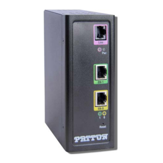
CopperLink Model 1314R User Manual 3 • CopperLink installation Installation Once the CL1314R is properly configured, it is ready to connect to the CopperLink interface and to the power source. This section explains how to make these connections. CopperLink™ Line Interface Power LED Line Link LED Ethernet Port 1... -
Page 26: Connecting The Ethernet Interface
CopperLink Model 1314R User Manual 3 • CopperLink installation Connecting the Ethernet interface This section describes how to connect the Ethernet ports to your network equipment. The interconnecting cables shall be acceptable for external use and shall be rated for the proper application with respect to volt- age, current, anticipated temperature, flammability, and CAUTION mechanical serviceability. -
Page 27: Dc Power Supply
Figure 7. DC Power Supply There are no user-servicable parts in the power supply section of the CL1314R. Fuse replacement should only be performed by qualified service personnel. See Chapter 6, “Contacting Patton WARNING on page 32. for assistance” Installation... -
Page 28: Operation
Chapter 4 Operation Chapter contents Introduction ................................29 Power-up ................................29 LED status monitors ............................29 Power (Green) ............................29 Line Link (Green) .............................29 ETH Link (Green) ............................29... -
Page 29: Introduction
CopperLink Model 1314R User Manual 4 • Operation Introduction Once the CL1314R is properly configured and installed, it should operate transparently. The following sec- tions describe power-up, reading the LED status monitors, and using the built-in loopback test modes. Power-up To apply power to the CL1314R, first be sure that you have read section “Power input connector”... -
Page 30: Software Upgrade
Chapter 5 Software Upgrade Chapter contents Introduction ................................31... -
Page 31: Introduction
CopperLink Model 1314R User Manual 5 • Software Upgrade Introduction The software upgrade feature is available through BOOTP/TFTP. The software upgrade takes approximately 2-3 minutes to complete. To upgrade the software: 1. Connect to the CL1314R via the Ethernet management port and a Telnet session. 2. -
Page 32: Contacting Patton For Assistance
Contacting Patton for assistance Chapter contents Introduction ................................33 Contact information..............................33 Patton support headquarters in the USA ......................33 Alternate Patton support for Europe, Middle East, and Africa (EMEA) ............33 Warranty Service and Returned Merchandise Authorizations (RMAs)..............33 Warranty coverage ............................33 Out-of-warranty service ..........................34 Returns for credit ............................34... -
Page 33: Introduction
(RMA). Contact information Patton Electronics offers a wide array of free technical services. If you have questions about any of our other products we recommend you begin your search for answers by using our technical knowledge base. Here, we have gathered together many of the more commonly asked questions and compiled them into a searchable database to help you quickly solve your problems. -
Page 34: Out-Of-Warranty Service
RMA#: xxxx 7622 Rickenbacker Dr. Gaithersburg, MD 20879-4773 USA Patton will ship the equipment back to you in the same manner you ship it to us. Patton will pay the return shipping costs. Warranty Service and Returned Merchandise Authorizations (RMAs) -
Page 35: A Compliance Information
Appendix A Compliance information Chapter contents Compliance ................................36 ................................36 Safety ................................36 Radio and TV Interference (FCC Part 15) ......................36 CE Declaration of Conformity ..........................36 Authorized European Representative ........................36... -
Page 36: Compliance
CE Declaration of Conformity Patton Electronics, Inc declares that this device is in compliance with the essential requirements and other rel- evant provisions of Directive 1999/5/EC. The Declaration of Conformity may be obtained from Patton Elec- tronics, Inc at www.patton.com/certifications. - Page 37 Appendix B Specifications Chapter contents Line rate ................................38 Ethernet interface ..............................38 Status LEDs................................38 Power (Green) ............................38 Line Link (Green) .............................38 ETH Link (Green) ............................38 Configuration................................38 Power and power supply specifications ........................39 External AC universal power supply ........................39 External 48 VDC power supply ........................39 Transmission line ..............................40...
-
Page 38: B Specifications
CopperLink Model 1314R User Manual B • Specifications Line rate 192 to 5696 kbps (64k increments) Ethernet interface Two RJ-45, 10/100Base-T, IEEE 802.3 Ethernet Status LEDs Power (Green) The Power LED glows solid during normal operation. At startup, during the POST, the LED blinks once every second. -
Page 39: Power And Power Supply Specifications
CopperLink Model 1314R User Manual B • Specifications Power and power supply specifications The CL1314R comes with either an AC or DC power supply: • The power connection to the CL1314R is a terminal block (see figure • There is one fuse in the equipment rated at 250V, 500 mA, 2 sec. •... -
Page 40: Transmission Line
Operating temp: 32–122°F (0–50°C) Humidity: 5–95% non-condensing Altitude: 0–15,000 feet (0–4,600 meters) Third party software licenses Note The CL1314R includes software developed under third party licenses. Con- tact Patton (Chapter 6, “Contacting Patton for assistance” on page 32) for more information. Transmission line... -
Page 41: Factory Replacement Parts And Accessories
Appendix C Factory replacement parts and accessories Chapter contents Factory replacement parts and accessories ......................42... -
Page 42: Factory Replacement Parts And Accessories
CopperLink Model 1314R User Manual C • Factory replacement parts and accessories Factory replacement parts and accessories Power Supplies PS-03671H1-004 100-240VAC (12V, DC/2A) Wall mount power adapter with terminal block Power Adapters 12-130 European replacement plug 12-129 American replacement plug 12-131 United Kingdom plug 12-132... -
Page 43: Interface Pinouts
Appendix D Interface pinouts Chapter contents Line port ................................44 Ethernet port.................................44... -
Page 44: Line Port
CopperLink Model 1314R User Manual D • Interface pinouts Line port RJ-45 connector Pin # Signal No connection No connection No connection Ring No connection No connection No connection Ethernet port Table 4. RJ45 socket 10/100Base-T Signal Note Pins not listed are not used. Line port...
Need help?
Do you have a question about the CopperLink 1314R and is the answer not in the manual?
Questions and answers