
Related Manuals for Advantech UNO-2050


Summary of Contents for Advantech UNO-2050
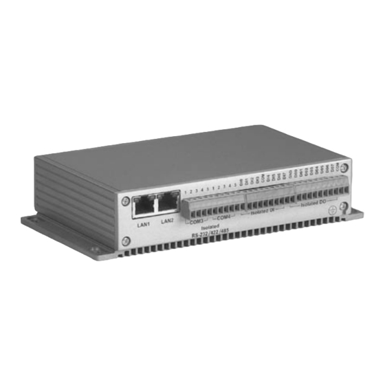
- Page 1 UNO-2050 GX1-300 Universal Network Controller with 2 x LAN, 2 x RS-232, 2 x isolated RS-232/422/485, 16 x isolated DI/O User’s Manual...
- Page 2 Copyright notice This document is copyrighted, 2002, by Advantech Co., Ltd. All rights are reserved. The original manufacturer reserves the right to make improvements to the products described in this manual at any time without notice. No part of this manual may be reproduced, copied, translated or transmitted in any form or by any means without the prior written permission of the original manufacturer.
-
Page 3: Product Warranty
Because of Advantech high quality-control standards and rigorous testing, most of our customers never need to use our repair service. If an Advantech product is defective, it will be repaired or replaced at no charge during the warranty period. For out-of-warranty repairs, you will be billed according to the cost of replacement materials, service time and freight. - Page 4 Technical support and sales assistance If you have any technical questions about the UNO-2050 or any other Advantech products, please visit our support website at: http://www.advantech.com/support For more information about Advantech’s products and sales informa- tion, please visit: http://www.advantech.com...
-
Page 5: Table Of Contents
Chaper 1 Overview ............. 1 Introduction ............... 2 Hardware Specifications ..........3 Safety Precautions ............6 UNO-2050 Series ............. 7 Chassis Dimensions ............8 Chaper 2 Hardware Functionality ......9 UNO-2050 Peripherals ..........10 COM1 ~ COM2: RS-232 Interfaces......10 COM3 ~ COM4: Isolated 5-wire RS-232/422/485 Interfaces .... - Page 6 A.6 PS/2 Keyboard and Mouse Connector (KM1) ..39 A.7 VGA Display Connector (VGA1) ......... 40 A.8 CompactFlashTM Master/Slave Jumper Setting (JP2) ................. 41 A.9 Enhanced IDE connctor (CN2) ........42 A.10 LCD connector (CN7, Reserved) ....... 43 A.11 UNO-2050 Control Register ........45...
- Page 7 32-bit Counter function block ..........20 Figure 3-1: Chassis Grounding connection ..........28 Figure A-1: UNO-2050 connector and jumper locations (Top View) ..32 Figure A-2: UNO-2050 connector and jumper locations (Bottom View) .. 32 Figure A-3: RS-485 Wiring topology ............38...
- Page 8 Table 2-17: Programmable LED control bit ..........26 Table 2-18: Programmable Buzzer control bit ........... 26 Table A-1: UNO-2050 connectors and jumpers ........33 Table A-2: RS-232 serial port pin assignments ........34 Table A-3 Isolated 5-wire RS-232/422/485 serial port pin assignments ..............
-
Page 9: Overview
UNO-2050 Overview This chapter gives background informa- tion on the UNO-2050. It shows you the UNO-2050 overview and specifications. Sections include: • Introduction • Hardware Specifications • Safety Precautions • UNO-2050 Series • Chassis Dimension... -
Page 10: Introduction
Ethernet, Wireless LAN, RS-232/422/485 and so on. Because of its openness, great expansion capability and reliable design – fanless and diskless, Advantech UNO-2000 series becomes an ideal embedded platform to implement custom applications in diversified applications. -
Page 11: Hardware Specifications
- Parity: non, even, odd - RS-232 Speed: 50 ~ 230.4 Kbps - RS-422/485 speed: 50 ~ 921.6 Kbps - 5-wire RS-232 data signals: TxD, RxD, RTS, CTS, GND - RS-422 data signals: TxD+, TxD-, RxD+, RxD-, GND Chapter 1 UNO-2050 Overview... - Page 12 - Keep output status after system hot reset - 5 ~ 40 V output range and 10 KHz speed - Plug-in screw-terminal block: Accepts 0.5 mm to 2.5 mm , 1 - #12 or 2 - #14 to #22 AWG UNO-2050 User's Manual...
- Page 13 Power Requirement: 1A typical under +24 V power input or 1.5 A typical under +12 V power input Operating temperature: -10 ~ 55°C (14 ~ 131°F) Chassis size: 164.8 mm (W) x 106.5 mm (L) x 35.5 mm (H) (6.5" x 4.2" x 1.4") Weight: 0.8 kg Chapter 1 UNO-2050 Overview...
-
Page 14: Safety Precautions
Caution! Always ground yourself to remove any static electric charge before touching UNO-2050. Modern electronic devices are very sensitive to static electric charges. Use a grounding wrist strap at all times. Place all electronic components on a static-dissipative surface or in a static-shielded bag.. -
Page 15: Uno-2050 Series
1.4 UNO-2050 Series There are two products in UNO-2050 series listed as below: • UNO-2050: UNO-2050 hardware platform • UNO-2050CE: UNO-2050 hardware platform with Windows CE OS (built in 32MB CompactFlash card) Packing list Before installing your board, make sure that the following materials... -
Page 16: Chassis Dimensions
1.5 Chassis Dimensions Figure 1-1: Chassis dimensions UNO-2050 User's Manual... -
Page 17: Hardware Functionality
Hardware Functionality This chapter shows how to set up the UNO-2050’s hardware functions, including connecting peripherals, switches and indicators. Sections include: • UNO-2050 Peripherals • COM 1 ~ COM 2: RS-232 Interfaces • COM 3 ~ COM 4: Isolated 5-wire RS-232/ 422/485 Interfaces •... -
Page 18: Uno-2050 Peripherals
2.1 UNO-2050 Peripherals The following two figures show the connectors on UNO-2050. The following sections give you detail information about function of each peripheral. Figure 2-1: UNO-2050 front panel Figure 2-2: UNO-2050 rear panel 2.2 COM1 ~ COM2: RS-232 Interfaces The UNO-2050 offers two standard RS-232 serial communication interface ports, and they are COM1 and COM2. -
Page 19: Com3 ~ Com4: Isolated 5-Wire Rs-232/ 422/485 Interfaces
CPU overhead and are an ideal choice for heavy multitasking environments. Automatic Data Flow Control Function for RS-485 In RS-485 mode, UNO-2050 automatically senses the direction of incoming data and switches its transmission direction accordingly. Therefore no handshaking signal (e.g. RTS signal) is necessary. This feature lets you simply and quickly build an RS-485 network with just two wires. -
Page 20: On-Board Isolated Digital Input
The UNO-2050 has 8 isolated digital input channels designated DI0~DI7. Pin Assignment The connector type of UNO-2050 is plug-in screw terminal block that enables you to connect to field I/O devices directly without additional accessories. Figure 2-3 and Table 2-2 shows its pin assignment as well as signal description. -
Page 21: Figure 2-4: Isolated Digital Input Connection
The channels are connected to the interrupt circuitry. Users can disable/enable interrupt function, select trigger type or latch the port data by setting the Interrupt Control Register of the UNO-2050. When the interrupt request signals occur, then the software will service these interrupt requests by ISR (Interrupt Service Routine). -
Page 22: Table 2-3: Interrupt Control Register Bit Map
DI0F & DO1F: DI0 & DI1 interrupt flag bit Interrupt Enable Control Function The user can choose to enable or disable the interrupt function by writing its corresponding value to the interrupt disable/enable control bit in the interrupt control register, as shown in Table 2-4 UNO-2050 User's Manual... -
Page 23: Table 2-4: Interrupt Disable/Enable Control Bit Values
Table 2-4: Interrupt disable/enable control bit values DI0EN & DI1EN Interrupt disable/enable control Disable Enable Interrupt Triggering Edge Control The interrupt can be triggered by a rising edge or a falling edge of the interrupt signal, as determined by the value in the interrupt triggering edge control bit in the interrupt control register, as shown in Table 2-5. -
Page 24: On-Board Isolated Digital Output
The UNO-2050 has 8 isolated digital output channels designated DO0~DO7. Pin Assignment The connector type of UNO-2050 is plug-in screw terminal block that enables you to connect to field I/O devices directly without additional accessories. Figure 2-5 and Table 2-7 shows its pin assignment as well as signal description. -
Page 25: Figure 2-6: Isolated Digital Output Connection
) is applied to an isolated output channel while it is being used as an output channel, the current will flow from the external voltage source to the UNO-2050. Please take care that the current through each DO pin not exceed 200 Figure 2-6 shows how to connect an external output load to the UNO- 2050’s isolated outputs. -
Page 26: On-Board Isolated Counter/Timer
They can be programmed to count from 2 up to 65535 or cascaded into one 32-bit counter. The UNO-2050 has 2 isolated counter input channels designated DI6 and DI7 or 2 isolated timer output channels designated DO6 and DO7. -
Page 27: Figure 2-7: Counter 0 Function Block
CTR0F & CTR1F: Counter 0 & Counter 1 interrupt flag bit CTR0Gate & CTR1Gate: Counter 0 and Counter 1 gate control bit CTR0Out & CTR1Out: Counter 0 and Counter 1 output status bit CTR0CLKSet & CTR1CLKSet: Counter 0 and Counter 1 clock source control bit CTR0GateSet &... -
Page 28: Figure 2-8: Counter 1 Function Block
CL K CT R 1F CT R 1OutS et=1 100K Hz E nabl e Inter r upt 10KH z CT R 1CL KS et=0 1K Hz 100H z S 1 S 0 Figure 2-9: 32-bit Counter function block UNO-2050 User's Manual... -
Page 29: Table 2-10 Counter Clock Source Control Bit
Counter clock source There are two clock sources available for the user counters by setting counter clock control bits - CTR0CLKSet and CTR1CLKSet. Table 2-10 Counter clock source control bit Counter clock control bit Internal clock (default) CTR0CLKSet External clock from digital input 6 (DI6) channel Internal clock (default) CTR1CLKSet... -
Page 30: Table 2-12 Counter Gate Source Control Bit
Output destination to “CTR0Out” status bit (Default) CTR0OutSet Output destination to “CTR0Out” status bit and digital output 6 (DO6) channel Gate destination to “CTR1Out” status bit. (Default) CTR1OutSet Output destination to “CTR1Out” status bit and digital output 7 (DO7) channel UNO-2050 User's Manual... -
Page 31: Table 2-14: Counter Interrupt Flag Control Bit
Counter interrupt flag The interrupt flag bit is a flag indicating the status of an interrupt. It is a readable/writable bit. To find the status of the interrupt, you have to read the bit value; to clear the interrupt, you have to write “1” to this bit. -
Page 32: Lan: Ethernet Connector
2.8 Power Connector The UNO-2050 comes with a Phoenix connector that carries 9 ~ 36 V external power input, and features reversed wiring protection. There- fore, it will not cause any damage to the system by reversed wiring of ground line and power line. -
Page 33: Vga: Vga Display Connector
2.11 VGA: VGA Display Connector The UNO-2050 provides a VGA controller for a high resolution VGA interface. It supports VGA and VESA, up to 1280 x 1024 @ 8 bpp and 1024 x 768 @ 16bpp resolution and up to 4 MB share memory. The VGA interface is reserved for system testing and debugging. -
Page 34: Reset: Reset Button
Light on Fast flickering Normal flickering Slow flickering Table 2-18: Programmable Buzzer control bit Buzzer alarming SPKS1 SPKS0 Beep on Short beep Normal beep Long beep 2.13 RESET: Reset Button Press “RESET” button will activate a reset function. UNO-2050 User's Manual... -
Page 35: Initial Setup
Initial Setup This chapter shows how to initial the UNO-2050, sections include: Sections include: • Insert CompactFlash Card • Chassis grounding • Connect the Power • Plug-in Screw Terminal Block Field Wiring Considerations • BIOS Setup and System Assignments... -
Page 36: Insert Compactflash Card
UNO-2050 is as follows, please follows these steps carefully. Step 1: Remove power cord. Step 2: Unscrew four screws from the rear panel of the UNO-2050. Step 3: Remove the rear panel. Step 4: Plug a CompactFlash card with user’s OS and application... -
Page 37: Connect The Power
Not connecting chassis ground with system power ground: 3.3 Connect the Power Connect the UNO-2050 to a 9 ~ 36 V power source. The power source can either be from a power adapter or an in-house power source. 3.4 Plug-in Screw Terminal Block Field... -
Page 38: Bios Setup And System Assignments
2.5” HDD. Some customers want to install a popular operating system, like Windows NT/2000 or need for larger data storage capability. UNO-2050 is also an ideal platform for applica- tions with HDD demand. Please contact Advantech to purchase UNO- 2050's HDD extension kit. -
Page 39: Appendix A Pin Assignments
Pin Assignments This appendix gives the UNO-2050 pin assignments • Board Connectors and Jumpers • Standard RS-232 Serial Port • Isolated 5-wire RS-232/422/485 Serial Port • Ethernet RJ-45 Connector • Phoenix Power Connector • PS/2 Keyboard and Mouse Connector • VGA Display Connector •... -
Page 40: Board Connector And Jumpers
There are connectors and jumpers on the UNO-2050 board. The following sections tell you how to configure the UNO-2050 hardware setting. Figure A-1 and figure A-2 show the locations of UNO-2050 connectors and jumpers. Figure A-1: UNO-2050 connector and jumper locations (Top View) -
Page 41: Table A-1: Uno-2050 Connectors And Jumpers
Table A-1: UNO-2050 connectors and jumpers Internal IDE connector Phoenix power connector Internal CompactFlash card slot LCD input from SOM-2353 CN1 LCD connector (reserved) COM1 COM1 standard RS-232 serial port COM2 COM2 standard RS-232 serial port CON1 COM3 and COM4. Isolated 5-wire RS-232/422/485... -
Page 42: Standard Rs-232 Serial Port (Com1~C0M2)
A.2 Standard RS-232 Serial Port (COM1~C0M2) Pin Assignments Table A-2: RS-232 serial port pin assignments RS-232 Signal Name UNO-2050 User's Manual... -
Page 43: Isolated 5-Wire Rs-232/422/485 Serial Port
A.3 Isolated 5-wire RS-232/422/485 Serial Port (COM3 ~ COM4) Pin Assignments COM3 COM4 Table A-3 Isolated 5-wire RS-232/422/485 serial port pin assignments Pin 5-wire RS-232 Signal Name RS-422 Signal Name RS-485 Signal Name TxD+ DATA+ TxD- DATA- RxD+ RxD- Note: NC represents “No Connection.” RS-232/422/485 Selection COM3 and COM4 support 5-wire RS-232, RS-422 or RS-485 interfaces, and you can set corresponding jumpers to select serial ports as RS-232... -
Page 44: Table A-5: Rs-485 Auto Flow Control Mode And Rs-422 Master/Slave
COM3 RS-485: N/A; RS-422: Master mode COM4 RS-485: Auto flow control; RS-422: Slave mode COM3 RS-485: Auto flow control; RS-422: Slave mode COM4 RS-485: N/A; RS-422: Master mode COM3 RS-485: N/A; RS-422: Master mode COM4 RS-485: N/A; RS-422: Master mode UNO-2050 User's Manual... -
Page 45: Table A-6: Jp7 Rs-422/485 Terminal Resistor Setting
Terminator Resistors Setup for RS-422/485 The 120Ω terminal resistors for impedance matching on the UNO-2050 are installed on board by selecting jumper JP7. Each terminal resistor corresponds to different channels for RS-422/485 signal lines. Usually, these resistors are needed for both ends of the communication wires and the value of the resistors should match the characteristic imped- ance of the wires used. -
Page 46: Ethernet Rj-45 Connector (Lan1~Lan2)
Figure A-3: RS-485 Wiring topology A.4 Ethernet RJ-45 Connector (LAN1~LAN2) Ethernet RJ-45 Connector Pin Assignments Table A-7: Ethernet RJ-45 connector pin assignments 10/100Base-T Signal Name XMT+ XMT- RCV+ RCV- UNO-2050 User's Manual... -
Page 47: Phoenix Power Connector (Cn3)
A.5 Phoenix Power Connector (CN3) Phoenix Power Connector Pin Assignments Table A-8: Phoenix power connector pin assignments Signal Name +10~30 V A.6 PS/2 Keyboard and Mouse Connector (KM1) PS/2 KB/MS Connector Pin Assignments Table A-9: Keyboard and Mouse connector pin assignments Signal Name KB DATA MS DATA... -
Page 48: Vga Display Connector (Vga1)
H-SYNC V-SYNC Chipset The UNO-2050 uses a Cyrix CS5530A chipset for its SVGA controller. It supports interlaced and non-interlaced analog monitors (color and monochrome VGA) in high-resolution modes while maintaining complete IBM VGA compatibility. Digital monitors (i.e. MDA, CGA and EGA) are NOT supported. -
Page 49: Compactflashtm Master/Slave Jumper Setting
Type I and type II (5mm thick) cards A 32 MB CompactFlash card is equipped in the UNO-2050CE with Windows CE .NET OS. For UNO-2050, there is no CompactFlash card on the slot. UNO-2050 also supports IBM Microdrive storage device, which is an ultra-miniature hard disk from IBM that was introduced in 1998. -
Page 50: Enhanced Ide Connctor (Cn2)
DATA 15 (*2) SIGNAL GND DMA REQUEST IO WRITE (*2) IO READ (*2) IO CHANNEL GND (*1) READY HDACK ADDR 1 ADDR 0 ADDR 2 HARD DISK HARD DISK SELECT 0 (*2) SELECT 1 (*2) IDE ACTIVE UNO-2050 User's Manual... -
Page 51: Lcd Connector (Cn7, Reserved)
A.10 LCD connector (CN7, Reserved) Table A-12: LCD connector Signal Name Signal Name +3.3V +3.3V PD10 PD11 PD12 PD13 PD14 PD15 PD16 PD17 FSCLK FVSYNC ENDISP FHSYNC FPEN VBIASEN Appendix A Pin Assignments... - Page 52 VBIASEN Flat Panel Backlight Enable Output. This is the enable signal for the backlight power supply to an attached flat panel. It is under control of the power sequence control logic. UNO-2050 User's Manual...
-
Page 53: Uno-2050 Control Register
A.11 UNO-2050 Control Register Table A-13: UNO-2050 control register Base Address Isolated Digital Input Status Register Base+00H Isolated Digital Output Control/Status Register Base+01H R/W Interrupt Enable Control/Status Register Base+02H R/W DI1EN DI0EN Interrupt Triggering Edge Control/Status Register Base+03H R/W DI1TE... - Page 54 UNO-2050 User's Manual...
Need help?
Do you have a question about the UNO-2050 and is the answer not in the manual?
Questions and answers