
Related Manuals for Advantech UNO-2182-D13BE


Summary of Contents for Advantech UNO-2182-D13BE
- Page 1 (217) 352-9330 | Click HERE Find the Advantech UNO-2182-D13BE at our website:...
- Page 2 UNO-2172 Pentium-M/Celeron-M Universal Network Controller with PCI-104 Expansion User Manual...
- Page 3 Copyright This document is copyrighted, © 2007. All rights are reserved. The origi- nal manufacturer reserves the right to make improvements to the products described in this manual at any time without notice. No part of this manual may be reproduced, copied, translated or transmit- ted in any form or by any means without the prior written permission of the original manufacturer.
- Page 4 Product Warranty Advantech warrants to you, the original purchaser, that each of its prod- ucts will be free from defects in materials and workmanship for one year from the date of purchase. This warranty does not apply to any products that have been repaired or...
- Page 5 This product has passed the CE test for environmental specifications when shielded cables are used for external wiring. We recommend the use of shielded cables. This kind of cable is available from Advantech. Please contact your local supplier for ordering information.
-
Page 6: Table Of Contents
Contents Chapter 1 Overview ............2 Introduction ............... 2 Hardware Specifications ........... 3 Safety Precautions ............. 4 Chassis Dimensions............5 Figure 1.1:Chassis Dimensions 1........5 Figure 1.2:Chassis Dimensions 2........5 Figure 1.3:Chassis Dimensions 3........5 Accessories................ 6 Chapter 2 Hardware Functionality ........8 Introduction ............... - Page 7 2.14 PCI-104 ................16 Figure 2.6:PCI-104 Power Selection ......16 Chapter 3 Initial Setup.............18 Chassis Grounding ............18 Figure 3.1:Chassis Grounding Connection....18 Inserting a CompactFlash Card ........18 Installing a Hard Disk ............. 19 Connecting Power ............20 BIOS Setup and System Assignments ......20 Installing PCI-104 Modules ..........
- Page 8 Overview This chapter provides an overview of UNO-2172’s specifications. Sections include: • Introduction • Hardware specification • Safety precautions • Chassis dimensions...
-
Page 9: Chapter 1 Overview
Controller is designed to be a total solution for network enabled Application Ready Platforms. Leveraging field-approved and worldwide approved real-time OS tech- nology, Advantech’s UNO-2000 series provides a Windows CE .NET and Windows XP Embedded ready solution, and supports several standard networking interfaces, such as Ethernet, Wireless LAN, RS-232/422/485 and so on. -
Page 10: Hardware Specifications
1.2 Hardware Specifications • CPU: Pentium M/ Celeron M • Memory: 1GB or 512MB on board • Battery-backup RAM: 512 KB Battery-backup RAM • Keyboard/Mouse: PS/2 keyboard & mouse • Display: DVI-I, support dual display • Serial Ports: 2 × RS-232 and 2 x RS-232/422/485 with DB-9 connectors. Automatic RS-485 data flow control •... -
Page 11: Safety Precautions
• Weight: 2.8 kg • Chassis Size (W × L × H): 255 x 152 x 69 mm (10”× 6.0”× 2.7”) • Software options: Windows XP Embedded, Win/2000/XP • Certification: CE, FCC Class A, UL 1.3 Safety Precautions The following sections tell how to make each connection. In most cases, you will simply need to connect a standard cable. -
Page 12: Chassis Dimensions
1.4 Chassis Dimensions Figure 1.1: Chassis Dimensions 1 Figure 1.2: Chassis Dimensions 2 Figure 1.3: Chassis Dimensions 3 Chapter 1... -
Page 13: Accessories
• PCI-104 bracket (Advantech P/N : 1960008884) • 2 Standard posts for install PCI-104 card (Advantech P/N : 193A231540) • 2 screws (M3*15L) for install PCI-104 bracket on UNO (Advantech P/ N : 1935131510) • Warranty card If anything is missing or damaged, contact your distributor or sales repre- sentative immediately. - Page 14 Hardware Functionality This chapter shows how to setup the UNO-2172’s hardware functions, including connecting peripherals, set- ting switches and indicators. Sections include: • Peripherals • RS-232 Interface • RS-232/422/485 Interface • LAN / Ethernet Connector • Power Connector • PS/2 Mouse and Keyboard Connector •...
-
Page 15: Chapter 2 Hardware Functionality
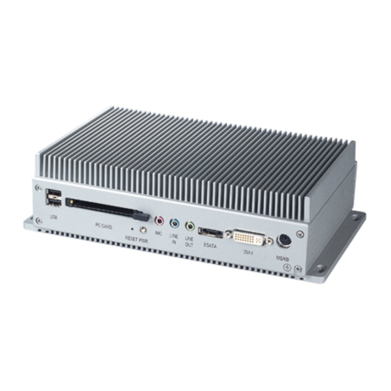
Chapter 2 Hardware Functionality 2.1 Introduction The following two figures show the connectors on UNO-2172. The fol- lowing sections give you detailed information about function of each peripheral. Figure 2.1: UNO-2172 Front Panel Figure 2.2: UNO-2172 Rear Panel 2.2 RS-232 Interface (COM1~COM2) The UNO-2172 offers two standard RS-232 serial communication inter- face ports: COM1 and COM2. -
Page 16: Rs-232/422/485 Interface (Com3~Com4)
COM3 and COM4. Please refer to Appendix A.4 for their pin assignments. The default setting of COM3 and COM4 are RS-422/485. 2.3.1 16C550 UARTs with 16-byte standard Advantech UNO-2172 comes with TI16C550 UARTs containing 16 bytes FIFOs. 2.3.2 RS-422/485 detection In RS-422/485 mode, UNO-2172 automatically detects signals to match RS-422 or RS-485 networks. -
Page 17: Rs-232/422/485 Selection
Description TX+/TX- for COM3 Data+/Data- for COM3 RX+/RX- for COM3 TX+/TX- for COM4 Data+/Data- for COM4 RX+/RX- for COM4 2.3.5 RS-232/422/485 Selection COM3 and COM4 support 9-wire RS-232, RS-422 and RS-485 inter- faces. The system detects RS-422 or RS-485 signals automatically in RS- 422/485 mode. -
Page 18: Rs-485 Auto Flow & Rs-422 Master/Slave Mode
2.3.6 RS-485 Auto Flow & RS-422 Master/Slave Mode You can set the “Auto Flow Control” mode of RS-485 or “Master/Slave” mode of RS-422 by using the SW4 DIP switch for each RS-422/485 port. In RS-485, if the switch is set to “Auto”, the driver automatically senses the direction of the data flow and switches the direction of transmission. -
Page 19: Irq And Address Setting
2.3.7 IRQ and Address Setting The IRQ and I/O address range of COM3 and COM4 are listed below: • COM3: 3E8 , IRQ10 (Independent IRQ), IRQ10 (Share IRQ) • COM4: 2E8 , IRQ5 (Independent IRQ), IRQ10 (Share IRQ) • Vector address for share IRQ: 1D0 You can set “Share IRQ”... -
Page 20: Lan: Ethernet Connector
2.4 LAN: Ethernet Connector The UNO-2172 is equipped with a Realtek RTL8111B Ethernet LAN controller that is fully compliant with IEEE 802.3u 10/100Mbps Ethernet and also IEEE 802.3ab 1000Mbps Ethernet.. The Ethernet port provides a standard RJ-45 jack on board, and LED indicators on the front side to show its Link (Green : 1000 Mbps network, Orange : 100 Mbps network, Blank : 10Mbps network.) and Active (Yellow LED) status. -
Page 21: Pcmcia: Pc Card Slot
2.9 VGA Display Connector UNO-2172 provides DVI-I interface, you could link you DVI or VGA monitor through DVI-I to DVI and VGA cable. (Advantech P/N : 1700004713), As for detail DVI-I pin assigmnet, please refer A.10. The UNO-2172 provides a VGA controller (Intel 915GM GMCH for a high resolution VGA interface. -
Page 22: Jumper Setting For Sram
Figure 2.5: SRAM Lithium Battery Location 2.10.2 Jumper Setting for SRAM You could set up SRAM enable or diable by jumper CN44. SRAM Enable/Disable Jumper Setting (CN44) Status Function Open Enable SRAM function (Default) Closed Disable SRAM function Chapter 2... -
Page 23: Reset Button
2.11 Reset Button Press the "Reset" button to activate the reset function. (SW2) 2.12 Power Button Press the "Power" button to power on or power off UNO-2172. (ATX type) (SW3) UNO-2172's power is also designed for power management only "S1" compliant. - Page 24 Initial Setup This chapter introduces how to initial- ize the UNO-2172. Sections include: • Chassis Grounding • Inserting a CompactFlash Card • Installing a Hard Disk • Connecting Power • BIOS Setup and System Assignments • Installing PCI-104 Modules...
-
Page 25: Chapter 3 Initial Setup
Chapter 3 Initial Setup 3.1 Chassis Grounding The aluminum made UNO-2172 provides good EMI protection and a sta- ble grounding base. There is an easy-to-connect chassis grounding point for you to use. Please connect chassis ground of UNO-2172 with "EARTH" as ground. Figure 3.1: Chassis Grounding Connection Note: UNO-2172 is design as system power ground... -
Page 26: Installing A Hard Disk
Note CN8 is primary's master CN7 is Primary Please do not use CN8 and CN7 at same time. If your OS is build in CF card and program,applica- tion and data are save in HDD, please install CF in CN8 and connect SATA HDD in CN40 (SATA signal) and CN41 (SATA power), please also refer CN40 and CN41 pin assignment in A.11. -
Page 27: Connecting Power
3.5 BIOS Setup and System Assignments UNO-2172 adopts Advantech’s SOM-5780 CPU module. Further infor- mation about the SOM-5780 CPU module, can be found in SOM-5780 user’s manual. You can find this manual on the UNO-2172’s driver and utility CD-ROM. -
Page 28: Installing Pci-104 Modules
3.6 Installing PCI-104 Modules If you need install PCI-104 module on UNO-2172, please refer below procedure. Make sure power core is not connected with UNO-2172. Unscrew the four screws from the rear panel. Slide off down cover of UNO-2172. Unscrew four screws from PCB, please refer below picture. Screw up 2 post and PCI-104 bracket in accessory, please refer below picture. - Page 29 Install PCI-104 card and screw up 4 screws which removed from UNO-2172 PCB, please refer below picture. Installation complete. Note: If only function test, UNO-2172 could integrate PCI-104 card without UNO-PCM22, if you need a whole set chassis, you have to assembly with UNO-PCM22 for whole UNO set.
- Page 30 System Settings and Pin Assignments...
-
Page 31: Appendix A System Settings & Pin Assignments
Appendix A System Settings & Pin Assignments A.1 System I/O Address & Interrupt Assignments Table A.1: UNO-2172 System I/O Ports Address Range Device 000-00F DMA controller 020-03F Interrupt controller 1, (master) 040-05F Timer/counter 060-06F (keyboard controller) 070-07F Real-time clock, non-maskable interrupt (NMI) Mask 080-09F DMA page register... - Page 32 Table A.1: UNO-2172 System I/O Ports Address Range Device 2E8-2EF Serial port 4 2F8-2FF Serial port 2 380-38F SDLC, bisynchronous 2 3A0-3AF Bisynchronous 1 3B0-3BF Monochrome display 3C0-3CF Reserved 3D0-3DF Color/graphics monitor adapter 3F0-3F7 Diskette controller 3E8-3EF Serial port 3 3F8-3FF Serial port 1 DC000-DFFFF...
-
Page 33: Board Connectors And Jumpers
A.2 Board Connectors and Jumpers There are several connectors and jumpers on the UNO-2172 board. The following sections tell you how to configure the UNO-2172 hardware set- ting. Figure A-1 and Figure A-2 show the locations of UNO-2172’s con- nectors and jumpers. Figure A.1: Connectors &... - Page 34 Table A.3: UNO-2172 Connectors and Jumpers Label Function Phoenix power connector CN31 Ethernet port 1 & 2 CN18 COM1 RS-232 serial port CN19 COM2 RS-232 serial port CN20 COM3 RS-232/422/485 serial port CN23 COM4 RS-232/422/485 serial port COM3/COM4 RS-422 master/slave selection Share IRQ/Independent IRQ selection /Speed selection CN24 COM3 RS-232/422/485 selection...
-
Page 35: Rs-232 Standard Serial Port (Com1~Com2)
A.3 RS-232 Standard Serial Port (COM1~COM2) Table A.4: RS-232 standard serial port pin assignments RS-232 Signal Name UNO-2172 User Manual... -
Page 36: Rs-232/422/485 Serial Port (Com3~Com4)
A.4 RS-232/422/485 Serial Port (COM3~COM4) Table A.5: RS-232/422/485 serial port pin assignments RS-232 RS-422 RS-485 DATA- DATA+ A.5 Ethernet RJ-45 Connector (LAN1~LAN2) Table A.6: Ethernet RJ-45 connector pin assignments 10/100/1000Base-T Signal Name XMT+ XMT- RCV+ RCV- Appendix A... -
Page 37: Phoenix Power Connector (Pwr)
A.6 Phoenix Power Connector (PWR) Table A.7: Power connector pin assignments Signal Name +9 ~36 VDC A.7 PS/2 Keyboard and Mouse Connector Table A.8: Keyboard and Mouse connector pin assignments Signal Name KB DATA MS DATA KB Clock MS Clock UNO-2172 User Manual... -
Page 38: Usb Connector (Usb1~Usb2)
A.8 USB Connector (USB1~USB2) Table A.9: USB connector pin assignments Signal Name Cable Color DATA- White DATA+ Green Black A.9 VGA Display Connector (DVI-I to DVI & VGA Cable) Table A.10: VGA adaptor cable pin assignment Signal Name Green Blue H-SYNC V-SYNC Appendix A... -
Page 39: Dvi-I Connector
A.10 DVI-I Connector Table A.11: DVI-I connector pin assignment Signal Name TMDS_C2# TMDS_C2 CRT_DDC_CLK CRT_DDC_DATA MDVI_CLK MDVI_DATA VGAVSY TMDS_C1# TMDS_C1 VCC_DVI VGA Detect HP_DET TMDS_C0# TMDS_C0 TMDS_CK# TMDS_CK VGAR VGAG VGAB VGAHSY UNO-2172 User Manual... -
Page 40: External & Internal Sata Connectors
A.11 External & Internal SATA Connectors Table A.12: External SATA connector pin assignment Signal name Table A.13: Internal SATA DATA Connectors (CN40) Signal name Appendix A... - Page 41 Table A.14: Internal SATA Power Connectors (CN41) Signal name +12V +12V UNO-2172 User Manual...
Need help?
Do you have a question about the UNO-2182-D13BE and is the answer not in the manual?
Questions and answers