Advantech Celeron M Universal Network Controller with PC/104 Extension UNO-2170 User Manual
Celeron m universal network controller with pc/104 extension
Hide thumbs
Also See for Celeron M Universal Network Controller with PC/104 Extension UNO-2170:
- User manual (36 pages)
Table of Contents
Advertisement
Quick Links
Advertisement
Table of Contents

Subscribe to Our Youtube Channel
Related Manuals for Advantech Celeron M Universal Network Controller with PC/104 Extension UNO-2170


Summary of Contents for Advantech Celeron M Universal Network Controller with PC/104 Extension UNO-2170
-
Page 1: User Manual
UNO-2170 Celeron M Universal Network Controller with PC/104 extension User Manual... - Page 2 Copyright This document is copyrighted, © 2004. All rights are reserved. The origi- nal manufacturer reserves the right to make improvements to the products described in this manual at any time without notice. No part of this manual may be reproduced, copied, translated or transmit- ted in any form or by any means without the prior written permission of the original manufacturer.
- Page 3 Product Warranty Advantech warrants to you, the original purchaser, that each of its products will be free from defects in materials and workmanship for one year from the date of purchase. This warranty does not apply to any products that have been repaired or altered by persons other than repair personnel authorized by Advantech, or which have been subject to misuse, abuse, accident or improper installation.
- Page 4 UNO-2170 User Manual...
-
Page 5: Table Of Contents
Contents Chapter 1 Overview ...2 Introduction ... 2 Hardware Specifications ... 3 Safety Precautions ... 4 Chassis Dimensions... 5 Figure 1.1:Chassis Dimensions... 5 Chapter 2 Hardware Functionality ...8 Introduction ... 8 Figure 2.1:Front panel of UNO-2170 ... 8 Figure 2.2:Rear panel of UNO-2170 ... 8 RS-232 Interface (COM1~COM2) ... - Page 6 Figure 3.1:Chassis Grounding Connection ... 18 Connecting Power ... 19 Installing a Hard Disk ... 19 BIOS Setup and System Assignments ... 19 Appendix A System Settings and Pin Assignments ...22 System I/O Address and Interrupt Assignment... 22 Table A.1: UNO-2170 System I/O Ports ... 22 Board Connectors and Jumpers...
- Page 7 Overview This chapter provides an overview of UNO-2170s specifications. Sections include: • Introduction • Hardware specification • Safety precautions • Chassis dimensions...
-
Page 8: Chapter 1 Overview
Chapter 1 Overview 1.1 Introduction UNO-2170 is an embedded Application Ready Platform (ARP) that can shorten your development time and offers rich networking interfaces to fulfill extensive needs in different projects. Advantech Universal Net- work Controller is designed to be a total solution for network enabled Application Ready Platforms. -
Page 9: Hardware Specifications
1.2 Hardware Specifications CPU: Up to Celeron-M 1GHz Ultra low-voltage version Memory: 256/512 MB DDR on board (Default: 256 MB DDR). Battery-backup RAM: 512 KB Battery-backup RAM VGA/Keyboard/Mouse: DB-15 VGA Connector, PS/2 keyboard and mouse Serial Ports: 2 x RS-232 and 2 x RS-232/422/485 with DB-9 connectors. Automatic RS-485 data flow control Serial Speeds: RS-232: 50~115.2 kbps, RS-422/485: 50~921.6 kbps LAN: Two 10/100 Base-T RJ-45 Ports... -
Page 10: Safety Precautions
1.3 Safety Precautions The following sections tell how to make each connection. In most cases, you will simply need to connect a standard cable. Warning! Always disconnect the power cord from your chassis whenever you are working on it. Do not connect while the power is on. -
Page 11: Figure 1.1:Chassis Dimensions
1.4 Chassis Dimensions Figure 1.1: Chassis Dimensions Chapter 1... - Page 12 UNO-2170 User Manual...
- Page 13 Hardware Functionality This chapter shows how to setup the UNO-2170s hardware functions, including connecting peripherals, setting switches and indicators. Sections include: • Peripherals • RS-232 Interface • RS-232/422/485 Interface • LAN / Ethernet Connector • Power Connector • PS/2 Mouse and Keyboard Connector •...
-
Page 14: Figure 2.1:Front Panel Of Uno-2170
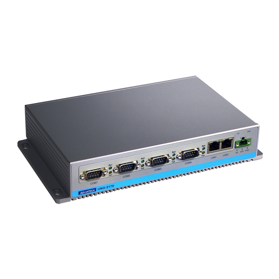
Chapter 2 Hardware Functionality 2.1 Introduction The following two figures show the connectors on UNO-2170. The following sections give you detailed information about function of each peripheral. Figure 2.1: Front panel of UNO-2170 Figure 2.2: Rear panel of UNO-2170 2.2 RS-232 Interface (COM1~COM2) The UNO-2170 offers two standard RS-232 serial communication inter- face ports: COM1 and COM2. -
Page 15: Rs-232/422/485 Interface (Com3~Com4)
2.3 RS-232/422/485 Interface (COM3~COM4) The UNO-2170 offers two RS-232/422/485 serial communication interface ports: COM3 and COM4. Please refer to Appendix A.4 for their pin assignments. The default setting of COM3 and COM4 are RS-422/485. 2.3.1 16C550 UARTs with 16-byte standard Advantech UNO-2170 comes with TI16C550 UARTs containing 16 bytes FIFOs. -
Page 16: Figure 2.3:Rs-422/485 Jumper Setting
2.3.5 RS-232/422/485 Selection COM3 and COM4 support 9-wire RS-232, RS-422 and RS-485 inter faces. The system detects RS-422 or RS-485 signals automatically in RS- 422/485 mode. To select between RS-422/485 and RS-232 for COM3, adjust JP4. To select between RS-422/485 and RS-232 for COM4, adjust JP5. Jumper setting for RS-422/485 interface: (Default setting). -
Page 17: Rs-485 Auto Flow Control Mode And Rs-422 Master/Slave Mode Selection
2.3.6 RS-485 Auto Flow Control Mode and RS-422 Master/Slave Mode Selection You can set the “Auto Flow Control mode of RS-485 or “Master/Slave" mode of RS-422 by using the SW3 DIP switch for each RS-422/485 port. In RS-485, if the switch is set to “Auto" the driver automatically senses the direction of the data flow and switches the direction of transmission. -
Page 18: Table 2.2:Irq Setting Via Switch 1 At Sw2
2.3.7 IRQ and Address Setting The IRQ and I/O address range of COM3 and COM4 are listed below: COM3: 3E8H, IRQ10 (Independent IRQ), IRQ10 (Share IRQ) COM4: 2E8H, IRQ5 (Independent IRQ), IRQ10 (Share IRQ) Vector address for share IRQ: 1D0H You can set “Share IRQ"... -
Page 19: Lan: Ethernet Connector
2.4 LAN: Ethernet Connector The UNO-2170 is equipped with a Realtek RTL8139C Ethernet LAN controller that is fully compliant with IEEE 802.3u 10/100Base-T CSMA/CD standards. The Ethernet port provides a standard RJ-45 jack on board, and LED indicators on the front side to show its Link (Green LED) and Active (Yellow LED) status. -
Page 20: Pcmcia: Pc Card Slot
2.8 PCMCIA: PC Card Slot The UNO-2170 provides one PC Card slot that supports CardBus (Card- 32) cards and 16-bit (PCMCIA 2.1/JEIDA 4.2) card standards. It supports +3.3 V, +5 V and +12 V @ 120 mA working voltage. The PC Card is 85.6 mm long by 54 mm wide (3.37"... -
Page 21: Battery Backup Sram
2.10 Battery Backup SRAM UNO-2170 provides 512 KB of battery backed SRAM. This ensures that you have a safe place to store critical data. You can now write software applications without being concerned that system crashes will erase criti- cal data from the memory. There is a BTRY LED in the front panel of the UNO-2170, please replace the lithium battery with a new one if the BTRY LED is activated. - Page 22 UNO-2170 User Manual...
- Page 23 Initial Setup This chapter introduces how to initialize the UNO-2170. Sections include: • Introduction • Inserting a CompactFlash™ Card • Chassis Grounding • Connecting Power • Connecting a Hard Disk • BIOS Setup and System Assignments...
-
Page 24: Chapter 3 Initial Setup
Chapter 3 Initial Setup 3.1 Inserting a CompactFlash Card The procedure for installing a CompactFlash™ card into the UNO-2170 is detailed below, please follow these steps carefully. 1. Remove the power cord. 2. Unscrew the four screws from the rear panel of the UNO-2170. 3. -
Page 25: Connecting Power
You can select if you wish to combine the chassis grounding point with the system grounding by using an onboard jumper selection. (JP7) Open - Separates system power ground and chassis ground. (default) Closed - Connects system power ground and chassis ground. - Page 26 UNO-2170 User Manual...
-
Page 27: System Settings And Pin Assignments
System Settings and Pin Assignments... -
Page 28: Table A.1: Uno-2170 System I/O Ports
Appendix A System Settings and Pin Assignments A.1 System I/O Address and Interrupt Assignment Table A.1: UNO-2170 System I/O Ports Address Range Device 000-01F DMA controller (slave) 020-03F Interrupt controller 1, (master) 040-05F 8254 timer/counter 060-06F 8042 (keyboard controller) 070-07F Real-time clock, non-mask interrupt (NMI) 080-09F DMA page register,... - Page 29 Table A.1: UNO-2170 System I/O Ports Address Range Device 3D0-3DF Color/graphics monitor adapter 3F0-3F7 Diskette controller 3E8-3EF Serial port 3 3F8-3FF Serial port 1 Watchdog timer DC000-DFFFF Battery backup resource Table A.2: UNO-2170 Interrupt Assignment Interrupt No. Interrupt Source Parity error detected IRQ 0 Interval timer IRQ 1...
-
Page 30: Board Connectors And Jumpers
A.2 Board Connectors and Jumpers There are several connectors and jumpers on the UNO-2170 board. The following sections tell you how to configure the UNO-2170 hardware setting. Figure A-1 and Figure A-2 show the locations of UNO-2170’s connectors and jumpers. Figure A.1: UNO-2170 connector and jumper locations (front-side) Figure A.2: UNO-2170 connector and jumper locations (back-side) UNO-2170 User Manual... - Page 31 Table A.3: UNO-2170 Connectors and Jumpers Label Function Phoenix power connector Ethernet port 1 Ethernet port 2 COM1 RS-232 serial port COM2 RS-232 serial port CN14 COM3 RS-232/422/485 serial port CN15 COM4 RS-232/422/485 serial port USB connector PS/2 keyboard and mouse connector Primary IDE connector Secondary IDE connector CN16...
-
Page 32: Rs-232 Standard Serial Port (Com1~Com2)
A.3 RS-232 Standard Serial Port (COM1~COM2) Table A.4: RS-232 standard serial port pin assignments RS-232 Signal Name UNO-2170 User Manual... -
Page 33: Rs-232/422/485 Serial Port (Com3~Com4)
A.4 RS-232/422/485 Serial Port (COM3~COM4) Table A.5: RS-232/422/485 serial port pin assignments RS-232 RS-422 A.5 Ethernet RJ-45 Connector (LAN1~LAN2) Table A.6: Table A-5: Ethernet RJ-45 connector pin assignments 10/100Base-T Signal Name XMT+ XMT- RCV+ RCV- RS-485 DATA- DATA+ Appendix A... -
Page 34: Phoenix Power Connector (Pwr)
A.6 Phoenix Power Connector (PWR) Table A.7: Power connector pin assignments 10/100Base-T Signal Name +9~36VDC A.7 PS/2 Keyboard and Mouse Connector Table A.8: Keyboard and Mouse connector pin assignments Signal Name KB DATA MS DATA KB Clock MS Clock UNO-2170 User Manual... -
Page 35: Usb Connector (Usb1~Usb2)
A.8 USB Connector (USB1~USB2) Table A.9: USB connector pin assignments Signal Name DATA+ DATA- A.9 VGA Display Connector Table A.10: Table A-9: VGA adaptor cable pin assignment Signal Name Green Blue H-SYNC V-SYNC Cable Color White Green Black Appendix A... - Page 36 UNO-2170 User Manual...
-
Page 37: Programming The Watchdog Timer
Programming the Watchdog Timer... -
Page 38: Appendix B Programming The Watchdog Timer
Appendix B Programming the Watchdog Timer Bellow is a sample of programming code for controlling the Watchdog Timer function. ----------------------------------------------------------------------------------- Enter the extended function mode, interruptible double-write | ----------------------------------------------------------------------------------- MOV DX,2EH MOV AL,87H OUT DX,AL OUT DX,AL ----------------------------------------------------------------------------- Configured logical device 8, configuration register CRF6 | ----------------------------------------------------------------------------- MOV DX,2EH MOV AL,2BH... - Page 39 Appendix B...
- Page 40 UNO-2170 User Manual...
Need help?
Do you have a question about the Celeron M Universal Network Controller with PC/104 Extension UNO-2170 and is the answer not in the manual?
Questions and answers