
Related Manuals for Solectria Renewables SGI 225


Summary of Contents for Solectria Renewables SGI 225
- Page 1 SGI 225 SGI 250 SGI 266 SGI 300 SGI 500 INSTALLATION AND OPERATION MANUAL Revision B © 2010, Solectria Renewables LLC Installation and Operation Manual Rev B...
-
Page 2: Important Safety Instructions
SGI Series Inverters IMPORTANT SAFETY INSTRUCTIONS In this manual “Inverter” or “Inverters” refers to the inverter models: SGI 225, SGI 250, SGI 266, SGI 300 and SGI 500 unless one of the specific models is noted. This manual contains important instructions that shall be followed during installation and maintenance of the SGI Inverter. - Page 3 Le SGI ne contient aucune pièce requérant un entretient effectué par l‘utilisateur. Pour toute maintenance, veuillez consulter Solectria Renewables ou un installateur agréé par Solectria Renewables (les coordonnées de Solectria Renewables et des installateurs agréés sont indiquées sur le site web de Solectria Renewables: www.solren.com.
-
Page 4: Table Of Contents
SGI Series Inverters Table of Contents Introduction………………………………………………………………..…………… Site Preparation and Inverter Placement..……………………..………… Inverter Positioning……..…………………………………...……… Mounting Details.……………………………………………..……… DC and AC Wire Entry Points. …………………………………… Installation………………………………….……………………………………………. Checking for Shipping Damage…………………………………. Inverter Mounting……………………………………………………. Electrical Connections and Connecting to Grid.……………………..…. Grounding Electrode Conductor……………………………….. DC Wiring…..……………………………………………………………… DC Ground Fault Detection and Interruption…………….. -
Page 5: Introduction
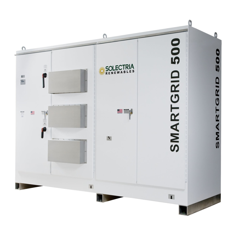
SGI Series Inverters 1 Introduction The SGI Series inverters (Smart Grid) are commercial, 3-phase grid-tied PV inverters designed to be inter-connected to the electric utility grid. By following this manual the Inverters can be installed and operated safely. This installation guide is used as reference for the commissioning and as a guideline on how to use the inverter most effectively. - Page 6 SGI Series Inverters Figure 1.2 The SGI Inverter Installation and Operation Manual (Rev B)
-
Page 7: Site Preparation And Inverter Placement
SGI Series Inverters 2.0 Site Preparation and Inverter Placement The Inverter is comprised of a rainproof industrial enclosure containing electrical and electronic components and AC and DC integrated disconnects. NOTE: If the Inverter is mounted outside, please make sure the enclosure doors remain closed during the installation process in case of rain or snow. - Page 8 SGI 500 6980 lbs. 8000 lbs SGI 300 5650 lbs. 6000 lbs SGI 225 255 266 5170 lbs 6000 lbs Table 2.1 Weight and Required fork lift capacity The ambient temperature must be between –25 C and +50 C for full power, continuous operation.
-
Page 9: Inverter Positioning
Correct mounting position for the inverter is vertical with the mounting feet on the floor. This diagram shows the basic inverter dimensions: 41” with blower shrouds. Figure 2.1 SGI 225 – SGI 500 dimensions 2.2 Mounting Details Using the mounting diagram Fig. 2.2, concrete pad mounting will be used. The inverter includes mounting feet with 8 holes (1/2”, 12mm diameter) on a 105”... - Page 10 SGI Series Inverters Figure 2.2 SGI Series mounting pattern (top view) It is recommended to use eight hot dip galvanized grade 5 or 8 steel bolts or stainless steel bolts. The correct bolt size is 3/8” (10mm) diameter. Use a heavy lock washer and flat washer with each bolt.
-
Page 11: Dc And Ac Wire Entry Points
SGI Series Inverters 2.3 DC and AC wire Entry Points AC and DC wiring must enter through the provided conduit cutout in the bottom of the inverter enclosure. Alternative locations are the left side for DC and back panel for AC. Alternate AC Conduit Entry Alternate DC... -
Page 12: Installation
Please inspect the inverter thoroughly after it is delivered. If any damage is seen please immediately notify the shipping company to make a claim. If there is any question about potential shipping damage, contact Solectria Renewables. A photo of the damage may be helpful. -
Page 13: Inverter Mounting
(right side enclosure). Use an 8,000lb For the SGI500 and 6,000lb for SGI 225-SGI300 capable forklift or fork attachment on other equipment if lifting from the bottom. The forks should be set at a 50"... - Page 14 SGI Series Inverters Figure 3.1 forklift lifting positions Use positions A when lifting or moving the inverter while attached to the pallet Use positions B when lifting or moving the inverter removed from the pallet. Note that the lifting diagrams show the inverter being lifted while mounted on the shipping pallet.
- Page 15 SGI Series Inverters Figure 3.2 Eyebolt lifting NOTE: Failure to follow the instructions may cause structural damage to the inverter and void the warranty. Installation and Operation Manual (Rev B)
-
Page 16: Electrical Connections And Connecting To Grid
SGI Series Inverters 4.0 DC Electrical Connections and Connection to the Electrical Utility Grid WARNING: All electrical installations shall be performed in accordance with all local electrical codes and the National Electrical Code, Canadian Electrical Code for Canada and ANSI/NFPA 70. Only make AC connections directly to the AC breaker and DC connections to the DC sub combiner panel. -
Page 17: Dc Wiring
SGI 500 : 32 positions 225 – 400 A fuses 110 – 200A 600VDC fuses 70 – 100A 600VDC fuses SGI 225 -300: 6 positions, SGI 225 -300: 12 positions SGI 500 : 24 positions 225 – 350A 600VDC fuses 110 –... - Page 18 SGI 500 : 8 positions SGI 500 : 16 positions SGI 500 : 24 or 32 positions SGI 225 -300: 6 or 8 positions SGI 225 -300: 12 or 16 SGI 225 -300: 24 positions 6-8 lugs...
- Page 19 SGI Series Inverters Up to 16 individual DC equipment ground connections can be made directly to the ground bond plate: Figure 4.2 DC equipment ground combiner lug positions (16 x 14AWG-2/0 lugs) Figure 4.3 DC equipment ground combiner lug position (1 x 0AWG-750MCM lug) Installation and Operation Manual (Rev B)
- Page 20 SGI Series Inverters Alternate AC Conduit Entry Alternate DC Conduit Entry AC and DC Conduit Plate Figure 4.4 AC and DC conduit cut-outs Connect the PV combined strings to the DC subcombiner fuse holders (ungrounded DC conductor) and negative subcombiner plate (grounded DC conductor). Connect the DC equipment ground to the ground bond plate.
-
Page 21: Dc Ground Fault Detection And Interruption
Breaker tripped DC Ground Fault Current Pickup Maximum Trip Time SGI 225 - 250 SGI 266 - 500 Table 4.5 WARNING: If the GFDI breaker trips upon connection of one or more combined strings you must locate and eliminate the ground fault in the array before proceeding. -
Page 22: Ac Wiring
Number of AC Minimum cable size Maximum cable size Torque Specs (in. terminals per phase kcmil lbs.) SGI 225 SGI 250 SGI 266 SGI 300 SGI 500 Table 4.6 Wire size limits 4.5 Connection Wiring to the Electrical Utility Grid The SGI Series Inverter must be connected to the grid with 3 conductors and an AC equipment- grounding conductor. - Page 23 SGI Series Inverters Example: Copper AWG needed to stay below recommended limit of 1% AC wire loss (400’ and over requires splicing 2 wires to maintain this low desired system resistance) All AC wiring must enter through the provided conduit cutout in the bottom on the inverter enclosure or the rear panel (see figure 4.4).
-
Page 24: Ac Ground Fault Detection
SGI Series Inverters 4.6 AC Ground Fault Detection Your SGI inverter is not equipped with an AC Ground Fault detection circuit. Where required by local electrical code, the inverter AC output needs to be connected to the supply side of the installation’s AC ground fault protection. -
Page 25: Solrenview Monitoring
SGI Series Inverters 4.8 SolrenView Monitoring SolrenView is a state of the art web based inverter monitoring system. The SGI series inverters are equipped with SolrenView monitoring DAS as part of the display module. If the customer has ordered and subscribed to SolrenView monitoring this must be turned on and Ethernet (CAT5) cable connected to the display module. -
Page 26: Commissioning The Inverter
SGI Series Inverters 7. Press to confirm 5.0 Commissioning the Inverter PV System The inverter is mounted, all connections are made and you are ready to power it up. NOTE: Make sure all tools, parts, etc. are removed from the vicinity of the inverter before turning on. -
Page 27: Display And Led
SGI Series Inverters Operating states, GFDI status and error indications shown by the LED indicators, which are described in chapter 6, “Power, GFDI and Error LED Indicators”. 6.0 LCD Display and LED Indicators The inverter operates automatically without the need for user interaction or maintenance. The Inverter automatically starts back feeding 3-phase AC power into the grid when there is sufficient DC voltage and PV power is available. - Page 28 SGI Series Inverters 6.1.2 Main/Default Screen Eac: XXXX kWh Pac: Press to move from the main/default screen into the Start Men u To enter into selected menu item, press the key. Start Menu 1. Measurements 2. Set Inverter 3. Set Monitor 4.
- Page 29 SGI Series Inverters Set Inverter Menu Displays inverter parameters, some of which may be modified with the keypad. 1. Inverter ID Serial port address/ID of the inverter 2. Baud Rate Serial port baud rate (19200 or 9600) 3. Power Level Inverter AC power output level 4.
-
Page 30: Led Lights
GFDI breaker needs to be reset after DC ground fault is green: GFDI breaker tripped removed in the array or the wiring leading up to the inverter see chapter 5 yellow: red: For other LED indications please contact Solectria Renewables Customer Support. Installation and Operation Manual (Rev B) -
Page 31: Troubleshooting And Lcd Messages
SGI Series Inverters 7 Troubleshooting, Inverter Messages Although the inverter is designed for many years of power production there may be instances where messages may be displayed on the LCD screen. For ease of diagnostics most messages are in plain English. Inverter Messages Possible Cause Possible Solution... - Page 32 SGI Series Inverters VAC Low The inverter had a “UL event” and is Wait for the inverter to restart Reconnecting in the 5 minute wait period Pac: XXXX W Grid voltage may not be present Check for grid voltage Waiting for grid Reverse phasing The VAC grid connection phasing does Change the phase wire positions at the...
-
Page 33: Warranty And Rma Policy
Duration of a Solectria Renewables Warranty Period: The warranty period is 60 months from the date of purchase of the SGI 225 / SGI 250/ SGI 266 / SGI 300 / SGI 500 by the end user or 64 months after the delivery date from Solectria Renewables to distributor or dealer/installer, whichever is shorter. - Page 34 SGI Series Inverters customer, end user or installer is required to pay return shipping fees to Solectria Renewables. Contact Solectria Renewables customer service for details on freight policy for return shipments outside of the contiguous United States and Canada. Shipping fees do not include duties, taxes or other Governmental charges.
- Page 35 Solectria Renewables product specifications including high input voltage from generators and lightning strikes; c) The product, if repairs have been done to it other than by Solectria Renewables or authorized, trained service personnel;...
- Page 36 Please refer to your product user manual for limitations on uses of the product. Specifically, please note that Solectria Renewables products are not intended for use in connection with life support systems and Solectria Renewables makes no warranty or representation in connection with any use of the product for such purposes.
-
Page 37: Return Material Authorization Policy
2) Include the following: a. The RMA number supplied by Solectria Renewables, LLC clearly marked on the outside of the b. A return address to which the unit can be shipped. Post office boxes are not acceptable. -
Page 38: Technical Data
SGI Series Inverters 9 Technical Data Technical Information and specifications – see appendix for complete SGI 225, SGI 250, SGI 266, SGI 300 and SGI 500 data sheet Input (DC) from PV array: Maximum open circuit voltage of PV array: 600V DC... -
Page 39: Dc Input
SGI Series Inverters 9.1 Input DC (PV) specifications Inverter Model SGI 225 SGI 250 SGI 266 SGI 300 SGI 500 Unit Operating voltage range (power) 300-600 Strike Voltage Input voltage MPP range 300-500 DC voltage measurement accuracy +/- 2% Max continuous power range... -
Page 40: Ac Output
The inverter is designed to work with the range of AC voltages for a 3-phase service defined by IEEE Std 1547-2003 and ANSI C84.1. Output (AC) specifications: Model SGI 225 SGI 250 SGI 266 SGI 300 SGI 500 Unit Operating AC voltage range 88 –... -
Page 41: Other Specifications
Automatic Forced Convection Enclosure Rain Proof UL1741 Enclosure-electronics IP-62 (sealed design) SGI 500 SGI 300 SGI 266 SGI 250 SGI 225 “strike” voltage DC (PV) Voltage (VDC) Figure 9.1 AC Output power of SGI Series inverters Installation and Operation Manual (Rev B) - Page 42 SGI Series Inverters 1600 1400 1200 1000 DC (PV) Input Voltage (VDC) Figure 9.2 Example maximum continuous DC current input for SGI 500 Efficiency of SGI 500kW-480VAC Grid-Tied Photovoltaic Inverter 100% AC Output Power (kW) Figure 9.3 SGI 500 efficiency plot at 360VDC input and 25C ambient temperature Installation and Operation Manual (Rev B)
-
Page 43: Appendix A Data Sheet Link
Appendix A – SGI 250, SGI 266, SGI 300 and SGI 500 Data Sheet http://www.solren.com/downloads/SGI250 SGI266_SGI300_SGI500.pdf Appendix B – String sizing http://www.solren.com/stringSizing.html Appendix C - Contact Information Solectria Renewables LLC 360 Merrimack Street Building 9, 2 floor Lawrence, Massachusetts 01843 Tel: 978.683.9700... -
Page 44: Appendix D Ul1741/Csa22.2 Listing Letter
SGI Series Inverters Appendix D – UL1741 IEEE 1547 CSA22.2#107.1 Listing letter: Installation and Operation Manual (Rev B)
Need help?
Do you have a question about the SGI 225 and is the answer not in the manual?
Questions and answers