Table of Contents
Advertisement
Quick Links
Download this manual
See also:
Instruction Manual
INSTRUCTION MANUAL
M ULT I MEDI A AU DIO A N D VI SU A L
MODEL : SB-5688LCM
8x8 HDMI MATRIX SWITCHER
8x8 HDMI Matrix Switcher
HDMI Matrix Switcher Series
Thank you for purchasing the SB-5688LCM HDMI Matrix Switcher. You will fi nd this unit easy to install and
highly reliable but it is essential that you read this manual thoroughly before attempting to use 8x8 HDMI Matrix
switcher.
Advertisement
Table of Contents

Related Manuals for Shinybow USA SB-5688LCM


Summary of Contents for Shinybow USA SB-5688LCM
- Page 1 HDMI Matrix Switcher Series Thank you for purchasing the SB-5688LCM HDMI Matrix Switcher. You will fi nd this unit easy to install and highly reliable but it is essential that you read this manual thoroughly before attempting to use 8x8 HDMI Matrix...
-
Page 2: Safety Information
SAFETY INFORMATION To ensure the best results from this product, please read this manual and all other documentation before operating your equipment. Retain all documentation for future reference. Follow all instructions printed on unit chassis for proper operation. To reduce the risk of fi re, do not spill water or other liquids into or on the unit, or operate the unit while standing in liquid. Make sure power outlets conform to the power requirements listed on the back of the unit. -
Page 3: Table Of Contents
Supporting eight (8) HDMI Inputs. Output supported (8) HDMI PSU if it is damaged. and (1) Preview output (same output-01). The SB-5688LCM is • Do not allow anything to rest on the power cabling or allow any based on the HDMI standard and supports full resolution HDMI weight to be placed upon it or any person walk on it. -
Page 4: Features & Specifications
FEATURES & SPECIFICATIONS FEATURES • 8x HDMI with DVI-Audio source devices matrix switched to 8x HDMI output devices. • HDMI digital Video w/ embedded HDCP, DVI format and CEC/HDCP 2.0 compliant • Worldwide control EDID modes for HD Video resolutions. •... -
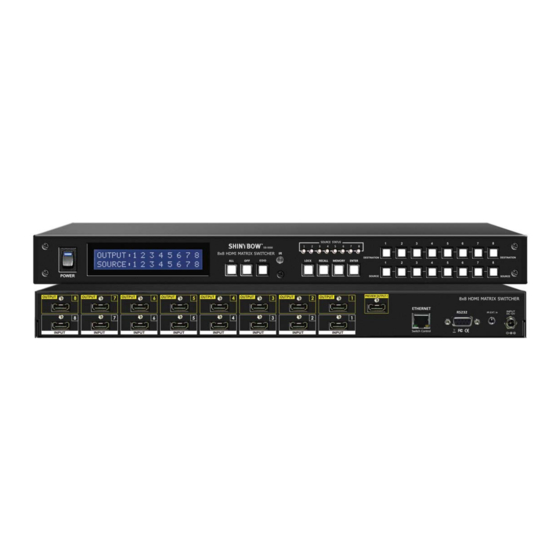
Page 5: Front Panel
FRONT PANEL FRONT PANEL 1. POWER SWITCH The power switch turns the unit on and off. The LCM will illuminate red to indicate that the switcher is ON and is receiving power. The Switcher will remember that last state during a power cycle. When power is removed and resorted, the last confi... - Page 6 FRONT PANEL FRONT PANEL 8. FUNCTION KEY - ALL Disables (mute) video on all destinations OR Selects the same source to all destinations. Option 1 - Press ALL followed by OFF button. The display will show “ 0 “ indicating all destinations have no video selected. Option 2 - Press ALL followed by Source 1 thru 8.
- Page 7 FRONT PANEL FRONT PANEL 12 FUNCTION KEY - MEMORY The system will show store presets, up to a total of 16. Presets are stored in local memory using Source keys 1 thru 8 or Destination keys 1 thru 8 as the memory preset location. - Confi...
-
Page 8: Rear Panel
REAR PANEL REAR PANEL 1. DC POWER INLET Power Jack: The Switcher is fi tted with a DC power plug input connector. Ensure that the DC Jack - Inner OD O 2.1mm (+ ) used is of an approved type and is of suffi cient current carrying connector Outside OD O 5.5mm (GND) capacity with the correct voltage and connector polarity. -
Page 9: Remote Control
REMOTE CONTROL Before making any connections to the switcher. Observe the following: > Ensure the mains voltage supply matches the label on the > Connect all audio video sources and destination equipment supplied plug-pack (+/- 10%) > Power up all source and destination audio-visual sources >... -
Page 10: Remote Protocol Commands
REMOTE PROTOCOL COMMANDS IR REMOTE CUSTOM AND DATA CODES (NEC STANDARD) HOW TO SETUP IR CODES : CUSTOM CODE : 09F6 : 09F6 B04F POWER ON : 09F6 A15E : 09F6 B14E POWER OFF : 09F6 A25D EDID : 09F6 B748 LOCK : 09F6 B54A RECALL... -
Page 11: Edid Functions
EDID FUNCTION EDID FUNCTION SETUP EDID Setup To Change the EDID Setup Step 1. Press the EDID button The display will show the currently selected EDID mode Step 2. Press SOURCE #1 or #2 button row The button will fl ash blue and the display will show the current Embedded EDID Status. Step 3. -
Page 12: Edid Function
EDID FUNCTION EDID FUNCTION : 8X EMBEDDED EDID MODES Mode 1. FSS (Fast Speed Start) Mode 5. H36-3D-M (1080p-36 bits) Fast Speed Start mode shortens the startup time of the switcher. Selecting this Video Support : All resolutions up to and including 1080p. mode does not force the EDID setup to be cancelled. - Page 13 EDID FUNCTION EDID FUNCTION FOR HDMI MATRIX SWITCHER EDID Status To view the current EDID status. Step 1. Press EDID button The button will fl ash blue and the display will show the current Embedded EDID Status. Step 2. Press EDID button To exit.
-
Page 14: Typical Application
TYPICAL APPLICATION INSTALLING DIAGRAM Sample connection using IR Transmitters (SB-101) and IR Receiver (SB-100) with SB-6335T & SB-6335R to control a projector. NOTE: 1. IR Control Projector Over HDBaseT Extender: SB-6335 HDBaseT Transmitter SB-6335R HDBaseT Receiver 2. Preview Output : Picture as same OUTPUT-1 3. - Page 15 TYPICAL APPLICATION INSTALLING DIAGRAM Sample connection using IR Transmitters (SB-101) and IR Receivers (SB-100) with SB-6335T and SB-6335R to control a Satellite Receiver. NOTE: 1. IR Control Satellite Receiver Over HDBaseT CAT5e/6/7 Extender from room: SB-6335 HDBaseT CAT5e/6/7 Transmitter SB-6335R HDBaseT CAT5e/6/7 Receiver 2.
-
Page 16: Ir Extender
IR EXTENDER IR RECEIVER: 1. SB-100 IR 300M Receiver Device Cable (3C) IR Receiver (SB-100) R oHS /95/E C INP UT R S -232 IR E XT. in DC 12V IR Rx RS - 232 IR EXT . SB-100 SB-100 IR Receiver Set SB-100 Maximum Distance ~ 984 feet (300 meters) 2. - Page 17 IR EXTENDER IR EMITTER: 1. SB-101 IR 300M Transmitter Device Cable (3C) IR Transmitter (SB-101) IR out CAT6/6a/7 DC 12V IR in R oHS /95/E C IR Tx From OUTPUT Receiver Receiver SB-101 SB-101 IR Transmitter Set SB-101 Maximum Distance ~ 984 feet (300 meters) 2.
-
Page 18: Rs-232 Serial Interface
Not used RS-232 PROTOCOL COMMANDS (RS-232 Control driver V2.0.1) The Shinybow switcher can be controlled via the RS-232 serial control port to allow for interfacing to a PC, or similar third party control system. The serial communication parameters are 9600 baud, 8 bit, No Parity and 1 stop bit - this is often referred to as 9600 8N1. When the unit... -
Page 19: Ethernet Serial Interface
ETHERNET SERIAL INTERFACE ETHERNET SERIAL INTERFACE CONNECT A PC OR CONTROL SYSTEM. VERSION COMPATIBLE V2.0 For a complete list of commands, please reference external document extended Ethernet Protocol Instruction Manual. ETHERNET SERIAL INTERFACE Pin Ethernet Reference TXOP TX + TXON TX - RXIP RX +... -
Page 20: Limited Warranty
LIMITED WARRANTY PLEASE READ THE FOLLOWING TERMS AND CONDITIONS CAREFULLY BEFORE USING THIS HARDWARE, COMPONENTS AND SOFTWARE PROVIDED BY, THROUGH OR UNDER SHINYBOWUSA, INC (COLLECTIVELY, THE “PRODUCT”). By using installing or using the Product, you unconditionally signify your agreement to these Terms and Conditions. If you do not agree to these Terms and Conditions, do not use the Product and return the Product to SHINYBOWUSA, Inc. - Page 21 M ULT IM EDI A AUDIO AN D V IS UA L 122 Rose Ln. Suite 303 | Frisco, Texas 75034 1-877-SHINY-USA 1-877-744-6987 1-972-377-2508 sales@shinybowusa.com www.shinybowusa.com...
Need help?
Do you have a question about the SB-5688LCM and is the answer not in the manual?
Questions and answers