D-Link DES-1228/ME User Manual
Managed 10/100mbps metro ethernet switch
Hide thumbs
Also See for DES-1228/ME:
- Reference manual (306 pages) ,
- Reference manual (413 pages) ,
- Hardware installation manual (53 pages)

Related Manuals for D-Link DES-1228/ME


Summary of Contents for D-Link DES-1228/ME
-
Page 1: User Manual
User Manual DES-1228/ME Product Model : Managed 10/100Mbps Metro Ethernet Switch Release 1 ©Copyright 2009. All rights reserved. - Page 2 Corporation. Other trademarks and trade names may be used in this document to refer to either the entities claiming the marks and names or their products. D-Link Corporation disclaims any proprietary interest in trademarks and trade names other than its own.
-
Page 3: Table Of Contents
DES-1228/ME Layer 2 Metro Ethernet Managed Switch Table of Contents Preface ......................................vii Intended Readers ..................................viii Typographical Conventions ................................ viii Notes, Notices, and Cautions ..............................viii Safety Instructions..................................ix Safety Cautions ......................................ix General Precautions for Rack-Mountable Products............................x Protecting Against Electrostatic Discharge .............................. - Page 4 DES-1228/ME Layer 2 Metro Ethernet Managed Switch Web Pages ........................................21 Administration ............................... 22 Device Information ..................................23 IP Address ....................................25 Setting the Swith’s IP Address using the Console Interface .......................... 27 Port Configuration..................................28 Port Settings ........................................28 Port Description ......................................
- Page 5 DES-1228/ME Layer 2 Metro Ethernet Managed Switch SMTP Server Settings ....................................66 SMTP Service ....................................... 66 L2 Features ..............................68 VLANs ......................................68 Static VLAN Entry ......................................72 GVRP Settings ......................................75 VLAN Trunk Settings ....................................77 Trunking ........................................78 Link Aggregation ......................................
- Page 6 DES-1228/ME Layer 2 Metro Ethernet Managed Switch Access Profile Table .................................. 127 CPU Interface Filtering ................................135 CPU Interface Filtering State ..................................135 CPU Interface Filtering Profile Table ................................. 135 Security ................................. 143 Traffic Control ................................... 143 Port Security ....................................147 Port Lock Entries ..................................
- Page 7 DES-1228/ME Layer 2 Metro Ethernet Managed Switch Packet Size ....................................198 MAC Address .................................... 200 Switch Log ....................................202 IGMP Snooping Group ................................203 Browse Router Port ..................................204 VLAN Status ....................................204 Static ARP Settings ..................................205 ARP-FDB ....................................205 Gratuitous ARP Settings ................................
-
Page 8: Preface
DES-1228/ME Layer 2 Metro Ethernet Managed Switch Preface The DES-1228/ME User Manual is divided into sections that describe the system installation and operating instructions with examples. Section 1, Introduction - Describes the Switch and its features. Section 2, Installation - Helps you get started with the basic installation of the Switch and also describes the front panel, rear panel, side panels, and LED indicators of the Switch. -
Page 9: Intended Readers
DES-1228/ME Layer 2 Metro Ethernet Managed Switch Intended Readers The DES-1228/ME User Manual contains information for setup and management of the Switch. The term, “the Switch” will be used when referring to the DES-1228/ME. This manual is intended for network managers familiar with network management concepts and terminology. -
Page 10: Safety Instructions
DES-1228/ME Layer 2 Metro Ethernet Managed Switch Safety Instructions Use the following safety guidelines to ensure your own personal safety and to help protect your system from potential damage. Throughout this document, the caution icon ( ) is used to indicate cautions and precautions that you need to review and follow. -
Page 11: General Precautions For Rack-Mountable Products
DES-1228/ME Layer 2 Metro Ethernet Managed Switch • To help protect your system from sudden, transient increases and decreases in electrical power, use a surge suppressor, line conditioner, or uninterruptible power supply (UPS). • Position system cables and power cables carefully; route cables so that they cannot be stepped on or tripped over. Be sure that nothing rests on any cables. -
Page 12: Protecting Against Electrostatic Discharge
DES-1228/ME Layer 2 Metro Ethernet Managed Switch CAUTION: The system chassis must be positively grounded to the rack cabinet frame. Do not attempt to connect power to the system until grounding cables are connected. A qualified electrical inspector must inspect completed power and safety ground wiring. An energy hazard will exist if the safety ground cable is omitted or disconnected. -
Page 13: Introduction
Installing SFP ports DES-1228/ME The DES-1228/ME is a member of the D-Link Switch family. This Switch provides unsurpassed performance, fault tolerance, scalable flexibility, robust security, standard-based interoperability and impressive technology to future-proof departmental and enterprise network deployments with an easy migration path. -
Page 14: Des-1228/Me
DES-1228/ME Layer 2 Fast Ethernet Managed Switch RFC2674 for 802.1p IEEE 802.1X MIB • IEEE 802.3x flow control in full duplex mode • IEEE 802.1p Priority Queues • IEEE 802.3u 100BASE-TX compliant • RS-232 DCE console port for Switch management •... -
Page 15: Ports
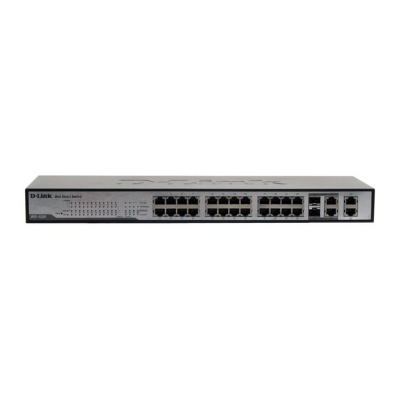
Two 1000Base-T/SFP Combo Ports Two 1000Base-T Ports One female DCE RS-232 DB-9 console port The following table lists the features and compatibility for each type of port present in the DES-1228/ME. 10/100/1000BASE-T SFP Combo 1000BASE-T Combo SFP Transceivers Supported: IEEE 802.3 compliant IEEE 802.3 compliant... -
Page 16: Led Indicators
LED Indicators The Switch supports LED indicators for Power, Console, RPS and Port LEDs. The following shows the LED indicators for the DES-1228/ME Series switches along with an explanation of each indicator. LEDs and there corresponding meanings are displayed below. -
Page 17: Front-Panel Description
Side Panel Description The left and right-hand panel of the DES-1228/ME Switch contains heat vents. The heat vents are used to dissipate heat. Do not block these openings, and leave at least 6 inches of space at the rear and sides of the Switch for proper ventilation. Be reminded... -
Page 18: Gigabit Combo Ports
Switch. Please note that although these two front panel modules can be used simultaneously, the ports must be different. The GBIC port will always have the highest priority. Figure 1- 5. Inserting the Mini-GBIC modules into the DES-1228/ME Switch Figure 1- 6. Installing the Mini-GBIC Module... -
Page 19: Installing The Sfp Ports
Installing the SFP ports The DES-1228/ME Switch is equipped with SFP (Small Form Factor Portable) ports, which are to be used with fiber-optical transceiver cabling in order to uplink various other networking devices for a gigabit link that may span great distances. These SFP... -
Page 20: Installation
• DCE RS-232 console cable If any item is missing or damaged, please contact your local D-Link Reseller for replacement. Before You Connect to the Network The site where you install the Switch may greatly affect its performance. Please follow these guidelines for setting up the Switch. -
Page 21: Installing The Switch Without The Rack
DES-1228/ME Layer 2 Fast Ethernet Managed Switch Installing the Switch without the Rack When installing the Switch on a desktop or shelf, the rubber feet included with the Switch should first be attached. Attach these cushioning feet on the bottom at each corner of the device. Allow enough ventilation space between the Switch and any other objects in the vicinity. -
Page 22: Mounting The Switch In A Standard 19" Rack
DES-1228/ME Layer 2 Fast Ethernet Managed Switch Mounting the Switch in a Standard 19" Rack CAUTION: Installing systems in a rack without the front and side stabilizers installed could cause the rack to tip over, potentially resulting in bodily injury under certain circumstances. Therefore, always install the stabilizers before installing components in the rack. -
Page 23: Connecting The Switch
DES-1228/ME Layer 2 Fast Ethernet Managed Switch Section 3 Connecting the Switch Switch to End Node Switch to Hub or Switch Connecting to Network Backbone or Server NOTE: All 10/100/1000Mbps NWay Ethernet ports can support both MDI-II and MDI-X con- nections. -
Page 24: Switch To Hub Or Switch
DES-1228/ME Layer 2 Fast Ethernet Managed Switch Switch to Hub or Switch These connections can be accomplished in a number of ways using a normal cable. • A 10BASE-T hub or switch can be connected to the Switch via a twisted-pair Category 3, 4 or 5 UTP/STP cable. -
Page 25: Introduction To Switch Management
DES-1228/ME Layer 2 Fast Ethernet Managed Switch Section 4 Introduction to Switch Management Management Options Web-based Management Interface SNMP-Based Management Managing User Accounts Command Line Console Interface through the Serial Port Connecting the Console Port (RS-232 DCE) First Time Connecting to the Switch... - Page 26 12. Enter the commands to complete your desired tasks. Many commands require administrator-level access privileges. Read the next section for more information on setting up user accounts. See the DES-1228/ME CLI Manual on the documentation CD for a list of all commands and additional information on using the CLI.
-
Page 27: First Time Connecting To The Switch
NOTE: Press Ctrl+R to refresh the screen. This command can be used at any time to force the console program in the Switch to refresh the console screen. Press Enter in both the Username and Password fields. You will be given access to the command prompt DES-1228/ME:4# shown below: There is no initial username or password. -
Page 28: Snmp Settings
The DES-1228/ME supports SNMP versions 1, 2c, and 3. You can specify which version of SNMP you want to use to monitor and control the Switch. The three versions of SNMP vary in the level of security provided between the management station and the network device. -
Page 29: Ip Address Assignment
DES-1228/ME Layer 2 Fast Ethernet Managed Switch Traps Traps are messages that alert network personnel of events that occur on the Switch. The events can be as serious as a reboot (someone accidentally turned OFF the Switch), or less serious like a port status change. The Switch generates traps and sends them to the trap recipient (or network manager). - Page 30 DES-1228/ME Layer 2 Fast Ethernet Managed Switch The IP address for the Switch must be set before it can be managed with the Web-based manager. The Switch IP address can be automatically set using BOOTP or DHCP protocols, in which case the actual address assigned to the Switch must be known.
-
Page 31: Web-Based Switch Configuration
DES-1228/ME Layer 2 Fast Ethernet Managed Switch Section 5 Web-based Switch Configuration Introduction Login to Web manager Web-Based User Interface Basic Setup Reboot Basic Switch Setup Network Management Switch Utilities Network Monitoring IGMP Snooping Status Introduction All software functions of the Switch can be managed, configured and monitored via the embedded web-based (HTML) interface. -
Page 32: Web-Based User Interface
Function Area 1 Select the folder or window to be displayed. The folder icons can be opened to display the hyper- linked window buttons and subfolders contained within them. Click the D-Link logo to go to the D- Link website. - Page 33 DES-1228/ME Layer 2 Fast Ethernet Managed Switch Area 2 Presents a graphical near real-time image of the front panel of the Switch. This area displays the Switch's ports and expansion modules, showing port activity, duplex mode, or flow control, depending on the specified mode.
-
Page 34: Web Pages
DES-1228/ME Layer 2 Fast Ethernet Managed Switch Web Pages When you connect to the management mode of the Switch with a web browser, a login window is displayed. Enter a user name and password to access the Switch's management mode. -
Page 35: Administration
DES-1228/ME Layer 2 Fast Ethernet Managed Switch Section 6 Administration IP Address Port Configuration DHCP/BOOTP Relay User Accounts Cable Diagnostics Port Mirroring System Log Settings Log Settings SNTP Settings MAC Notification Settings TFTP Services Multiple Image Services Ping Test Safeguard Engine SNMP Manager Forwarding &... -
Page 36: Device Information
DES-1228/ME Layer 2 Fast Ethernet Managed Switch Device Information This window contains the main settings for all major functions of the Switch and appears automatically when you log on. To return to the Device Information window, click the DES-1228/ME Web Management Tool folder. - Page 37 DES-1228/ME Layer 2 Fast Ethernet Managed Switch System Location Enter the location of the Switch, if so desired. System Contact Enter a contact name for the Switch, if so desired. Serial Port Auto Select the logout time used for the console interface. This automatically logs the user out after Logout Time an idle period of time, as defined.
-
Page 38: Ip Address
The IP address may initially be set using the console interface prior to connecting to it through the Ethernet. If the Switch IP address has not yet been changed, read the introduction of the DES-1228/ME CLI Manual or return to Section 4 of this manual for more information. - Page 39 DES-1228/ME Layer 2 Fast Ethernet Managed Switch NOTE: The Switch's factory default IP address is 10.90.90.90 with a subnet mask of 255.0.0.0 and a default gateway of 0.0.0.0. To use the BOOTP or DHCP protocols to assign the Switch an IP address, subnet mask, and default gateway address: Use the Get IP From pull-down menu to choose from BOOTP or DHCP.
-
Page 40: Setting The Swith's Ip Address Using The Console Interface
DES-1228/ME Layer 2 Fast Ethernet Managed Switch Setting the Swith’s IP Address using the Console Interface Each Switch must be assigned its own IP Address, which is used for communication with an SNMP network manager or other TCP/IP application (for example BOOTP, TFTP). The Switch’s default IP address is 10.90.90.90. You can change the default Switch IP address to meet the specification of your networking address scheme. -
Page 41: Port Configuration
DES-1228/ME Layer 2 Fast Ethernet Managed Switch Port Configuration This section contains information for configuring various attributes and properties for individual physical ports, including port speed and flow control. Port Settings Click Administration > Port Configuration > Port Settings to display the following window: To configure switch ports: Choose the port or sequential range of ports using the From…To…... - Page 42 DES-1228/ME Layer 2 Fast Ethernet Managed Switch From…. To Use the pull-down menus to select the port or range of ports to be configured. State Toggle this field to either enable or disable a given port or group of ports.
-
Page 43: Port Description
DES-1228/ME Layer 2 Fast Ethernet Managed Switch Port Description The Switch supports a port description feature where the user may name various ports on the Switch. To assign names to various ports, click Administration > Port Configuration > Port Description to view the following window:... - Page 44 DES-1228/ME Layer 2 Fast Ethernet Managed Switch State Describes the current running state of the port, whether Enabled or Disabled. Connection This field will show if a port has been disabled due to an error detected in the port. Reason Describes the reason why the port has been error-disabled, such as a STP loopback occurrence.
-
Page 45: Dhcp/Bootp Relay
DES-1228/ME Layer 2 Fast Ethernet Managed Switch DHCP/BOOTP Relay To enable and configure DHCP/BOOTP Relay Global Settings on the Switch, click Administration > DHCP/BOOTP Relay > DHCP/BOOTP Relay Global Settings: DHCP/BOOTP Relay Global Settings Figure 6- 6. DHCP/ BOOTP Relay Global Settings window... - Page 46 DES-1228/ME Layer 2 Fast Ethernet Managed Switch check and policy settings will have no effect. DHCP Relay Agent This field can be toggled between Enabled and Disabled using the pull-down menu. It is Information Option 82 used to enable or disable the Switches ability to check the validity of the packet’s option 82 Check field.
- Page 47 DES-1228/ME Layer 2 Fast Ethernet Managed Switch The Implementation of DHCP Information Option 82 in the DES-1228/ME switches The config dhcp_relay option_82 command configures the DHCP relay agent information option 82 setting of the switch. The formats for the circuit ID sub-option and the remote ID sub-option are as follows: NOTE: For the circuit ID sub-option of a standalone switch, the module field is always zero.
-
Page 48: Dhcp/Bootp Relay Interface Settings
DES-1228/ME Layer 2 Fast Ethernet Managed Switch DHCP/BOOTP Relay Interface Settings This window allows the user to set up a server, by IP address, for relaying DHCP/ BOOTP information to the Switch. The user may enter a previously configured IP interface on the Switch that will be connected directly to the DHCP/BOOTP server using the following window. - Page 49 DES-1228/ME Layer 2 Fast Ethernet Managed Switch Figure 6- 8. DHCP Local Relay Settings window...
-
Page 50: User Accounts
DES-1228/ME Layer 2 Fast Ethernet Managed Switch The following parameters may be configured or viewed. Parameter Description DHCP/BOOTP Local Used to Enable or Disable the DHCP/BOOTP Local Relay Operation State. Relay Operation State VLAN Name This is the VLAN Name that identifies the VLAN the user wishes to apply the DHCP/BOOTP Local Relay Operation. - Page 51 DES-1228/ME Layer 2 Fast Ethernet Managed Switch Figure 6- 11. User Account Modify Table window Modify or delete an existing user account in the User Account Modify Table. To delete the user account, click on the Delete button. To change the password, type in the New Password and retype it in the Confirm New Password entry field. The level of privilege (Admin or User) can be viewed in the Access Right field.
-
Page 52: Cable Diagnostics
DES-1228/ME Layer 2 Fast Ethernet Managed Switch Cable Diagnostics The following window is used to test the cables connecting to the Switch. This feature is used to determine if there are any errors on the copper cables and the position where the errors may have occurred. Use the pull down menu to enter the port or range of ports to be tested and click the Test Now button which will display the the results in the Cable Diagnostics Information table below. - Page 53 DES-1228/ME Layer 2 Fast Ethernet Managed Switch If there are no problems with the cable the test results will show that the cable is OK, if Test Results there are no cables connected to the port the results will show No Cable.
-
Page 54: Port Mirroring
DES-1228/ME Layer 2 Fast Ethernet Managed Switch Port Mirroring The Switch allows you to copy frames transmitted and received on a port and redirect the copies to another port. You can attach a monitoring device to the mirrored port, such as a sniffer or an RMON probe, to view details about the packets passing through the first port. -
Page 55: System Log Settings
DES-1228/ME Layer 2 Fast Ethernet Managed Switch System Log Settings The Switch can send Syslog messages to up to four designated servers using the System Log Server. To view this window click Administration > System Log Settings, to view the window shown below. - Page 56 DES-1228/ME Layer 2 Fast Ethernet Managed Switch kernel messages user-level messages mail system system daemons security/authorization messages messages generated internally by syslog line printer subsystem network news subsystem UUCP subsystem clock daemon security/authorization messages FTP daemon NTP subsystem log audit...
-
Page 57: Log Settings
DES-1228/ME Layer 2 Fast Ethernet Managed Switch Log Settings The Log settings can be changed by clicking the System Log Settings link to open the following window: Figure 6- 17. Log Settings window The following parameters can be set: Parameter... -
Page 58: Sntp Settings
DES-1228/ME Layer 2 Fast Ethernet Managed Switch SNTP Settings Time Settings This window is used to configure the time settings for the Switch. To view this window click, Administration > SNTP Settings > Time Settings. Figure 6- 18. Time Settings window... -
Page 59: Time Zone And Dst
DES-1228/ME Layer 2 Fast Ethernet Managed Switch Time in HH MM SS Enter the current time in hours, minutes, and seconds. Click Apply to implement changes made. Time Zone and DST The following are windows used to configure time zones and Daylight Savings time settings for SNTP. Open the Administration folder, then the SNTP Settings folder and click on the Time Zone and DST link, revealing the following window. - Page 60 DES-1228/ME Layer 2 Fast Ethernet Managed Switch Time Zone Offset Use these pull-down menus to specify your local time zone's offset from Greenwich Mean from GMT in +/- Time (GMT.) HH:MM DST Repeating Settings Using repeating mode will enable DST seasonal time adjustment. Repeating mode requires that the DST beginning and ending date be specified using a formula.
-
Page 61: Mac Notification Settings
DES-1228/ME Layer 2 Fast Ethernet Managed Switch MAC Notification Settings MAC Notification is used to monitor MAC addresses learned and entered into the forwarding database. To globally set MAC notification on the Switch, click Administration > MAC Notification Settings. Global Settings... -
Page 62: Tftp Services
DES-1228/ME Layer 2 Fast Ethernet Managed Switch TFTP Services Trivial File Transfer Protocol (TFTP) services allow the Switch's firmware to be upgraded by transferring a new firmware file from a TFTP server to the Switch. A configuration file can also be loaded into the Switch from a TFTP server. -
Page 63: Multiple Image Services
DES-1228/ME Layer 2 Fast Ethernet Managed Switch Multiple Image Services To configure the files located on the Flash memory, use the following windows to guide you. The Multiple Image Services folder contains windows to allow the user to view Firmware Information and to configure Firmware Image, to view these windows click Administration >... -
Page 64: Ping Test
DES-1228/ME Layer 2 Fast Ethernet Managed Switch Ping Test Ping is a small program that sends ICMP Echo packets to the IP address you specify. The destination node then responds to or "echoes" the packets sent from the Switch. This is very useful to verify connectivity between the Switch and other nodes on the network. - Page 65 DES-1228/ME Layer 2 Fast Ethernet Managed Switch Figure 6- 25. Safeguard Engine example For every consecutive checking interval that reveals a packet flooding issue, the Switch will double the time it will discard ingress ARP and IP broadcast packets. In the example above, the Switch doubled the time for dropping ARP and IP broadcast packets when consecutive flooding issues were detected at 5 second intervals.
- Page 66 DES-1228/ME Layer 2 Fast Ethernet Managed Switch Figure 6- 27. Safeguard Engine Settings window – CPU Utilization Settings To set the Safeguard Engine for the Switch, complete the following fields: Parameter Description State Toggle this field to either Enabled or Disabled for the Safeguard Engine of the Switch.
-
Page 67: Snmp Manager
The DES-1228/ME supports the SNMP versions 1, 2c, and 3. The default SNMP setting is enabled and cannot be disabled. The three versions of SNMP vary in the level of security provided between the management station and the network device. -
Page 68: Snmp Traps Settings
DES-1228/ME Layer 2 Fast Ethernet Managed Switch SNMP Traps Settings The following window is used to enable and disable trap settings for the SNMP function on the Switch. To view this window for configuration, click Administration > SNMP Manager > SNMP Trap Settings: Figure 6- 28. - Page 69 DES-1228/ME Layer 2 Fast Ethernet Managed Switch V2 - Indicates that SNMP version 2 is in use. V3 - Indicates that SNMP version 3 is in use. Auth-Protocol None - Indicates that no authentication protocol is in use. MD5 - Indicates that the HMAC-MD5-96 authentication level will be used.
-
Page 70: Snmp View Table
DES-1228/ME Layer 2 Fast Ethernet Managed Switch SNMP View Table This window is used to assign views to community strings that define which MIB objects can be accessed by a remote SNMP manager. To view the SNMP View Table window, click Administration > SNMP Manager > SNMP View Table. -
Page 71: Snmp Group Table
DES-1228/ME Layer 2 Fast Ethernet Managed Switch SNMP Group Table An SNMP Group created with this table maps SNMP users (identified in the SNMP User Table) to the views created in the previous menu. To view the SNMP Group Table window, click Administration > SNMP Manager > SNMP Group Table. -
Page 72: Snmp Community Table Configuration
DES-1228/ME Layer 2 Fast Ethernet Managed Switch Figure 6- 36. SNMP Group Table Configuration window The following parameters can set: Parameter Description Group Name Type an alphanumeric string of up to 32 characters. This is used to identify the new SNMP group of SNMP users. -
Page 73: Snmp Host Table
DES-1228/ME Layer 2 Fast Ethernet Managed Switch Figure 6- 37. SNMP Community Table Configuration window The following parameters can set: Parameter Description Community Name Type an alphanumeric string of up to 32 characters that is used to identify members of an SNMP community. -
Page 74: Snmp Engine Id
DES-1228/ME Layer 2 Fast Ethernet Managed Switch The following parameters can set: Parameter Description Host IP Address Type the IP address of the remote management station that will serve as the SNMP host for the Switch. SNMP Version V1 - To specifies that SNMP version 1 will be used. -
Page 75: Multicast Forwarding
DES-1228/ME Layer 2 Fast Ethernet Managed Switch To add or edit an entry, define the following parameters and then click Add/Modify: Parameter Description The VLAN ID number of the VLAN on which the above Unicast MAC address resides. MAC Address The MAC address to which packets will be statically forwarded. - Page 76 DES-1228/ME Layer 2 Fast Ethernet Managed Switch Address address. Port Settings Allows the selection of ports that will be members of the static multicast group. The options are: None - When None is chosen, the port will not be a member of the Static Multicast Group.
-
Page 77: Multicast Filtering Mode
DES-1228/ME Layer 2 Fast Ethernet Managed Switch Multicast Filtering Mode The following figure and table describe how to set up multicast forwarding on the Switch. To view this window, click Administration > Forwarding & Filtering > Multicast Filtering Mode: Figure 6-44. Multicast Filtering Mode window... -
Page 78: Smtp Service
DES-1228/ME Layer 2 Fast Ethernet Managed Switch SMTP Service SMTP or Simple Mail Transfer Protocol is a function of the Switch that will send switch events to mail recipients based on e-mail addresses entered using the commands below. The Switch is to be configured as a client of SMTP while the server is a remote device that will receive messages from the Switch, place the appropriate information into an e-mail and deliver it to recipients configured on the Switch. -
Page 79: Smtp Server Settings
DES-1228/ME Layer 2 Fast Ethernet Managed Switch SMTP Server Settings The following window is used to configure the fields to set up the SMTP server for the switch, along with setting e-mail addresses to which switch log files can be sent when a problem arises on the Switch. To open the following window, click Administration >... - Page 80 DES-1228/ME Layer 2 Fast Ethernet Managed Switch Figure 6-46. SMTP Service window The following parameters can be set: Parameter Description Subject Enter the subject of the test e-mail. Content Enter the content of the test e-mail. Once your message is ready, click Send to send this mail to all recipients configured on the Switch for SMTP.
-
Page 81: L2 Features
DES-1228/ME Layer 2 Fast Ethernet Managed Switch Section 7 L2 Features VLAN Trunking IGMP Snooping Spanning Tree Loopback Detection LLDP VLANs A Virtual Local Area Network (VLAN) is a network topology configured according to a logical scheme rather than the physical layout. -
Page 82: Q Vlan Tags
DES-1228/ME Layer 2 Fast Ethernet Managed Switch 802.1Q-compliant switches through a single physical connection and allows Spanning Tree to be enabled on all ports and work normally. The IEEE 802.1Q standard restricts the forwarding of untagged packets to the VLAN of which the receiving port is a member. -
Page 83: Tagging And Untagging
DES-1228/ME Layer 2 Fast Ethernet Managed Switch Figure 7- 2. IEEE 802.1Q Tag The EtherType and VLAN ID are inserted after the MAC source address, but before the original EtherType/Length or Logical Link Control. Because the packet is now a bit longer than it was originally, the Cyclic Redundancy Check (CRC) must be recalculated. -
Page 84: Vlan Segmentation
DES-1228/ME Layer 2 Fast Ethernet Managed Switch An example is presented below: VLAN Name Switch Ports System (default) 5, 6, 7, 8, 21, 22, 23, 24 Engineering 9, 10, 11, 12 Marketing 13, 14, 15, 16 Finance 17, 18, 19, 20... -
Page 85: Static Vlan Entry
Asymmetric VLANs The DES-1228/ME Switch Series has the capability to create and utilize Asymmetric VLANs on the Switch. Asymmetric VLANs allow devices to transmit packets on one VLAN and receive it on another VLAN. This configuration is accomplished through the use of three functions: enabling Asymmetric VLANs, VLAN creation, and GVRP configuration. - Page 86 DES-1228/ME Layer 2 Fast Ethernet Managed Switch Figure 7- 5. Static VLANs Entry Settings window The 802.1Q Static VLANs window lists all previously configured VLANs by VLAN ID and VLAN Name. To delete an existing 802.1Q VLAN, click the corresponding button under the Delete heading.
- Page 87 DES-1228/ME Layer 2 Fast Ethernet Managed Switch Port Settings Allows an individual port to be specified as member of a VLAN. Specifies the port as either 802.1Q tagging or 802.1Q untagged. Checking the box will desig- nate the port as Tagged.
-
Page 88: Gvrp Settings
DES-1228/ME Layer 2 Fast Ethernet Managed Switch None Allows an individual port to be specified as a non-VLAN member. Egress Select this to specify the port as a static member of the VLAN. Egress member ports are ports that will be transmitting traffic for the VLAN. These ports can be either tagged or untagged. - Page 89 DES-1228/ME Layer 2 Fast Ethernet Managed Switch Figure 7- 8. GVRP Settings window The following fields can be set: Parameter Description From/To These two fields allow you to specify the range of ports that will be included in the Port-based VLAN that you are creating using this window.
-
Page 90: Vlan Trunk Settings
DES-1228/ME Layer 2 Fast Ethernet Managed Switch Check to compare the VID tag of an incoming packet with the PVID number assigned to the port. If the two are different, the port filters (drops) the packet. Disabled disables ingress filtering. Ingress Checking is Disabled by default. -
Page 91: Trunking
DES-1228/ME Layer 2 Fast Ethernet Managed Switch Figure 7- 9. VLAN Trunk Port Settings window Trunking Port trunk groups are used to combine a number of ports together to make a single high-bandwidth data pipeline. The Switch supports up to six port trunk groups with 2 to 8 ports in each group. A potential bit rate of 800 Mbps can be achieved. -
Page 92: Link Aggregation
DES-1228/ME Layer 2 Fast Ethernet Managed Switch 802.1p default priority configurations must be identical. Port locking, port mirroring and 802.1X must not be enabled on the trunk group. Further, the aggregated links must all be of the same speed and should be configured as full-duplex. - Page 93 DES-1228/ME Layer 2 Fast Ethernet Managed Switch Figure 7- 13. LACP Port Settings window To configure LACP port trunk settings, select a port range using the From and To drop-down menus, select either Passive or Active Mode, and then click Apply to let your changes take effect.
-
Page 94: Igmp Snooping
DES-1228/ME Layer 2 Fast Ethernet Managed Switch IGMP Snooping Internet Group Management Protocol (IGMP) snooping allows the Switch to recognize IGMP queries and reports sent between network stations or devices and an IGMP host. When enabled for IGMP snooping, the Switch can open or close a port to a specific device based on the IGMP messages passing through the Switch. - Page 95 DES-1228/ME Layer 2 Fast Ethernet Managed Switch the IGMP Snooping Settings. VLAN Name This is the VLAN Name that, along with the VLAN ID, identifies the VLAN for which to modify the IGMP Snooping Settings. Query Interval This field is used to set the time (in seconds) between transmitting IGMP queries. Entries between 1 and 65535 seconds are allowed.
-
Page 96: Router Ports Settings
DES-1228/ME Layer 2 Fast Ethernet Managed Switch Router Ports Settings A static router port is a port that has a multicast router attached to it. Generally, this router would have a connection to a WAN or to the Internet. Establishing a router port will allow multicast packets coming from the router to be propagated through the network, as well as allowing multicast messages (IGMP) coming from the network to be propagated to the router. - Page 97 DES-1228/ME Layer 2 Fast Ethernet Managed Switch Figure 7- 17. Router Ports Settings - Edit window The following parameters can be viewed: Parameter Description VID (VLAN ID) This is the VLAN ID that, along with the VLAN Name, identifies the VLAN where the multicast router is attached.
-
Page 98: Dynamic Ip Multicast Learning
DES-1228/ME Layer 2 Fast Ethernet Managed Switch Dynamic IP Multicast Learning To configure the Dynamic IP Multicast Learning Max Entry Settings on the Switch, click L2 Features > IGMP Snooping > Dynamic IP Multicast Learning. Figure 7-18. Dynamic IP Multicast Learning Settings window... -
Page 99: Ism Vlan Settings
DES-1228/ME Layer 2 Fast Ethernet Managed Switch ISM VLAN Settings In a switching environment, multiple VLANs may exist. Every time a multicast query passes through the Switch, the switch must forward separate different copies of the data to each VLAN on the system, which, in turn, increases data traffic and may clog up the traffic path. - Page 100 DES-1228/ME Layer 2 Fast Ethernet Managed Switch Enter a name for the ISM VLAN into the VLAN Name field and choose a VID between 2 and 4094. Entries in these two fields must not have been previously configured on the switch or an error message will be prompted to the user. Once these two fields have been filled, click the Apply button, which will automatically adjust the current window to resemble the following window.
-
Page 101: Spanning Tree
This Switch supports three versions of the Spanning Tree Protocol; 802.1d STP, 802.1w Rapid STP and MSTP. 802.1d STP will be familiar to most networking professionals. However, since 802.1w RSTP has been recently introduced to D-Link managed Ethernet switches, a brief introduction to the technology is provided below followed by a description of how to set up 802.1d STP and 802.1w RSTP. -
Page 102: Port Transition States
DES-1228/ME Layer 2 Fast Ethernet Managed Switch The IEEE 802.1w Rapid Spanning Tree Protocol (RSTP) evolved from the 802.1d STP standard. RSTP was developed in order to overcome some limitations of STP that impede the function of some recent switching innovations, in particular, certain Layer 3 functions that are increasingly handled by Ethernet switches. -
Page 103: Stp Bridge Global Settings
Yet, even this function can malfunction with the emergence of STP BPDU packets that occasionally loopback to the Switch, such as BPDU packets looped back from an unmanaged switch connected to the DES- 1228/ME. To maintain the consistency of the throughput, the DES-1228/ME now implements the STP LoopBack prevention function. - Page 104 DES-1228/ME Layer 2 Fast Ethernet Managed Switch Figure 7-24. STP Bridge Global Settings window – RSTP Figure 7- 25. STP Bridge Global Settings window – MSTP...
- Page 105 DES-1228/ME Layer 2 Fast Ethernet Managed Switch Figure 7- 26. STP Bridge Global Settings window – STP Compatible The following parameters can be set: Parameter Description Spanning Tree Protocol Use the pull-down menu to enable or disable STP globally on the Switch. The default is Disabled.
- Page 106 DES-1228/ME Layer 2 Fast Ethernet Managed Switch on the Switch. MSTP − Select this parameter to set the Multiple Spanning Tree Protocol (MSTP) globally on the Switch TX Hold Count (1-10) Used to set the maximum number of Hello packets transmitted per interval. The count can be specified from 1 to 10.
-
Page 107: Stp Port Settings
DES-1228/ME Layer 2 Fast Ethernet Managed Switch STP Port Settings STP can be set up on a port per port basis. To view the STP Port Settings window click L2 Features > Spanning Tree > STP Port Settings: Figure 7- 27. STP Port Settings window In addition to setting Spanning Tree parameters for use on the switch level, the Switch allows for the configuration of groups of ports, each port-group of which will have its own spanning tree, and will require some of its own configuration settings. - Page 108 DES-1228/ME Layer 2 Fast Ethernet Managed Switch will be chosen to forward packets. Hello Time This can be set from 1 to 2 seconds. This is the interval between two transmissions of BPDU packets sent by the Root Bridge to tell all other switches that it is indeed the Root Bridge.
-
Page 109: Mst Configuration Identification
DES-1228/ME Layer 2 Fast Ethernet Managed Switch MST Configuration Identification The following windows in the MST Configuration Identification section allow the user to configure a MSTI instance on the Switch. These settings will uniquely identify a multiple spanning tree instance set on the Switch. The Switch initially possesses one CIST or Common Internal Spanning Tree of which the user may modify the parameters for but cannot change the MSTI ID for, and cannot be deleted. - Page 110 DES-1228/ME Layer 2 Fast Ethernet Managed Switch The user may configure the following parameters to create a MSTI in the Switch. Parameter Description MSTI ID Enter a number between 1 and 4 to set a new MSTI on the Switch.
-
Page 111: Stp Instance Settings
DES-1228/ME Layer 2 Fast Ethernet Managed Switch Figure 7- 31. Instance ID Settings window – modify The user may configure the following parameters for a MSTI on the Switch. Parameter Description MSTI ID Displays the MSTI ID previously set by the user. -
Page 112: Mstp Port Information
DES-1228/ME Layer 2 Fast Ethernet Managed Switch Click the Modify button to change the priority of the MSTI. This will open the Instance ID Settings window to configure. Figure 7- 33. Instance ID Settings - modify priority window The following parameters can be viewed or set:... - Page 113 DES-1228/ME Layer 2 Fast Ethernet Managed Switch Figure 7- 35. MSTI Settings window The following parameters can be viewed or set: Parameter Description Instance ID Displays the MSTI ID of the instance being configured. An entry of 0 in this field denotes the CIST (default MSTI).
-
Page 114: Loopback Detection Settings
DES-1228/ME Layer 2 Fast Ethernet Managed Switch Loopback Detection Settings The Loopback Detection function is used to detect the loop created by a specific port. This feature is used to temporarily shutdown a port on the Switch when a CTP (Configuration Testing Protocol) packet has been looped back to the switch. -
Page 115: Lldp
DES-1228/ME Layer 2 Fast Ethernet Managed Switch Interval (1-32767) Set a Loopdetect Interval between 1 and 32767 seconds. The default is 10 seconds. Recover Time Time allowed (in seconds) for recovery when a Loopback is detected. The Loopdetect (0 or 60-1000000) Recover Time can be set at 0 seconds, or 60 to 1000000 seconds. - Page 116 DES-1228/ME Layer 2 Fast Ethernet Managed Switch Figure 7- 37. LLDP Operation State Settings window The following parameters can be set: Parameter Description LLDP Operation When this function is Enabled, the switch can start to transmit LLDP packets and receive and State process the LLDP packets.
-
Page 117: Basic Lldp Port Settings
DES-1228/ME Layer 2 Fast Ethernet Managed Switch Basic LLDP Port Settings The following window is used to set up LLDP on individual port(s) on the Switch. To view this window click L2 Features > LLDP > Basic LLDP Port Settings. -
Page 118: 802.1 Extension Lldp Port Settings
DES-1228/ME Layer 2 Fast Ethernet Managed Switch Parameter Description From/To Select a port or group of ports using the pull-down menus. Notification State Used to configure each port for sending notification to configured SNMP trap receiver(s). Enable or disable each port for sending change notification to configured SNMP trap receiver(s) if an LLDP data change is detected in an advertisement received on the port from an LLDP neighbor. - Page 119 DES-1228/ME Layer 2 Fast Ethernet Managed Switch Figure 7- 39. 802.1 Extension LLDP Port Settings Table window...
-
Page 120: Extension Lldp Port Settings
DES-1228/ME Layer 2 Fast Ethernet Managed Switch The following parameters can be set or displayed: Parameter Description From/To Select a port or group of ports using the pull-down menus. Port VLAN ID Use the drop-down menu to toggle Port VLAN ID between Enabled and Disabled. - Page 121 DES-1228/ME Layer 2 Fast Ethernet Managed Switch Figure 7- 40. 802.3 Extension LLDP Port Settings Table window The following parameters can be set or displayed: Parameter Description From/To Select a port or group of ports using the pull-down menus. MAC/PHY...
-
Page 122: Lldp Management Address Settings
DES-1228/ME Layer 2 Fast Ethernet Managed Switch Configuration/Status Disabled. Link Aggregation Use the drop-down menu to toggle Link Aggregation between Enabled and Disabled. Maximum Frame Use the drop-down menu to toggle Maximum Frame Size between Enabled and Disabled. Size Click Apply to implement changes made. -
Page 123: Lldp Statistics
DES-1228/ME Layer 2 Fast Ethernet Managed Switch Parameter Description From/To Select a port or group of ports using the pull-down menus. Address Type Displays the IPV4 Address type. Address Enter the LLDP management address in this field. Port State Use the drop-down menu to toggle the Port State between Enabled and Disabled. -
Page 124: Lldp Management Address Table
DES-1228/ME Layer 2 Fast Ethernet Managed Switch LLDP Management Address Table The following window is used to make entries to and display the LLDP Management Address Table. To view this window click L2 Features > LLDP > LLDP Management Address Table. -
Page 125: Lldp Remote Port Table
DES-1228/ME Layer 2 Fast Ethernet Managed Switch LLDP Remote Port Table The following window is used to display the LLDP Remote Port Brief Table. To view this window click L2 Features > LLDP > LLDP Remote Port Table. Figure 7- 45. LLDP Remote Port Brief Table window... -
Page 126: Cos
DES-1228/ME Layer 2 Fast Ethernet Managed Switch Section 8 Port Bandwidth 802.1p Default Priority 802.1p User Priority CoS Scheduling Mechanism CoS Output Scheduling Priority Settings TOS Priority Settings DSCP Priority Settings Port Mapping Priority Settings MAC Priority The Switch supports 802.1p priority queuing Quality of Service. The following section discusses the implementation of CoS (Quality of Service) and benefits of using 802.1p priority queuing. -
Page 127: Understanding Cos
DES-1228/ME Layer 2 Fast Ethernet Managed Switch Figure 8- 1. An Example of the Default CoS Mapping on the Switch The picture above shows the default priority setting for the Switch. Class-3 has the highest priority of the four priority classes of service on the Switch. - Page 128 DES-1228/ME Layer 2 Fast Ethernet Managed Switch sent in the following sequence: A1~A4, B1~B3, C1~C2, D1, A5~A8, B4~B6, C3~C4, D2, A9~A12, B7~B9, C5~C6, D3, A13~A16, B10~12, C7~C8, D4, A17~A20, B13~15, C9~C10, D5, B16~18, C11~C12, D6, B19~B20, C13~14, D7, C15~C16, D8, C17~C18, D9, C19~20, D10, D11~20.
-
Page 129: Port Bandwidth
DES-1228/ME Layer 2 Fast Ethernet Managed Switch Port Bandwidth The bandwidth control settings are used to place a ceiling on the transmitting and receiving data rates for any selected port. To view this window click CoS > Port Bandwidth. Figure 8- 2. Port Bandwidth window... -
Page 130: 802.1P Default Priority
DES-1228/ME Layer 2 Fast Ethernet Managed Switch Parameter Description From/To A consecutive group of ports may be configured starting with the selected port. Type This drop-down menu allows you to select between RX (receive,) TX (transmit,) and Both. This setting will determine whether the bandwidth ceiling is applied to receiving, transmitting, or both receiving and transmitting packets. - Page 131 DES-1228/ME Layer 2 Fast Ethernet Managed Switch Figure 8- 3. 802.1p Default Priority window This window allows you to assign a default 802.1p priority to any given port on the Switch. The priority tags are numbered from 0, the lowest priority, to 7, the highest priority. To implement a new default priority choose a port range by using the From and...
-
Page 132: 802.1P User Priority
DES-1228/ME Layer 2 Fast Ethernet Managed Switch 802.1p User Priority When using 802.1p priority mechanism, the packet is examined for the presence of a valid 802.1p priority tag. If the tag is present, the packet is assigned to a programmable egress queue based on the value of the tagged priority. The tagged priority can be designated to any of the available queues. -
Page 133: Cos Output Scheduling
DES-1228/ME Layer 2 Fast Ethernet Managed Switch The Scheduling Mechanism has the following parameters. Parameter Description Strict Denoting a Strict scheduling will set the highest queue to be emptied first while the other queues will follow the weighted round-robin scheduling scheme. -
Page 134: Priority Settings
DES-1228/ME Layer 2 Fast Ethernet Managed Switch Priority Settings The Priority Setting window will allow users to configure the CoS priority settings on a port per port basis. When CoS tagged packets arrive on the switch, they are mapped to the settings configured here. For example, if a port has been assigned a MAC priority, the packet that has the CoS priority assigned to a MAC address will be sent to the CoS queue configured for that MAC address. - Page 135 DES-1228/ME Layer 2 Fast Ethernet Managed Switch Figure 8- 7. Priority Settings window...
-
Page 136: Tos Priority Settings
DES-1228/ME Layer 2 Fast Ethernet Managed Switch Configure the following Priority Setting parameters: Parameter Description From/To Users may select a port or group of ports to assign ToS priority settings, based on the following Main Select field. Main Select Select the general priority settings for the ports previously stated using the pull-down menu. -
Page 137: Dscp Priority Settings
DES-1228/ME Layer 2 Fast Ethernet Managed Switch DSCP Priority Settings When using the DSCP/TOS priority mechanism, the packet is classified based on the DSCP/TOS field in the IP header. If the tag is present, the packet is assigned to a programmable egress queue based on the value of the tagged priority. The tagged priority can be designated to any of the available queues. -
Page 138: Port Mapping Priority Settings
DES-1228/ME Layer 2 Fast Ethernet Managed Switch Port Mapping Priority Settings When using the port-based priority mechanism, the port-based priority (high or low) assigned to each ingress port determines the egress queue assigned to frames arriving via the given ingress port. The frames will be assigned to either the highest queue or the lowest queue. -
Page 139: Mac Priority
DES-1228/ME Layer 2 Fast Ethernet Managed Switch MAC Priority When using the MAC Priority mechanism, the packet is classified based on the MAC address field priority in the MAC priority table entries. To configure a destination MAC address for a CoS queue, users must adhere to the following steps: Users must first enter a static destination MAC address into the Forwarding Database (FDB) of the switch. -
Page 140: Acl
DES-1228/ME Layer 2 Fast Ethernet Managed Switch Section 9 Access Profile Table CPU Interface Filtering Access Profile Table Access profiles allow you to establish criteria to determine whether or not the Switch will forward packets based on the information contained in each packet's header. - Page 141 DES-1228/ME Layer 2 Fast Ethernet Managed Switch Figure 9- 2. Access Profile Configuration window (Ethernet) The following parameters can be set, for the Ethernet type: Parameter Description Profile ID (1-256) Type in a unique identifier number for this profile set. The number is used to set the relative priority for the profile.
- Page 142 DES-1228/ME Layer 2 Fast Ethernet Managed Switch Figure 9- 3. Access Profile Configuration window (IP) The following parameters can be set, for IP: Parameter Description Profile ID (1-256) Type in a unique identifier number for this profile set. The number is used to set the relative priority for the profile.
- Page 143 DES-1228/ME Layer 2 Fast Ethernet Managed Switch guidelines: Select ICMP to instruct the Switch to examine the Internet Control Messages Protocol (ICMP) field in each frame's header. Select IGMP to instruct the Switch to examine the Internet Group Management Protocol (IGMP) field in each frame's header.
- Page 144 DES-1228/ME Layer 2 Fast Ethernet Managed Switch Figure 9- 5. Access Rule Configuration window (IP) Configure the following Access Rule Configuration settings: Parameter Description Profile ID This is the identifier number for this profile set. Mode Select Permit to specify that the Switch, according to any additional rule, forward the packets that match the access profile added (see below).
- Page 145 DES-1228/ME Layer 2 Fast Ethernet Managed Switch Destination IP Enter an IP Address mask for the destination IP address. DSCP (0-63) This field allows the user to enter a DSCP value in the space provided, which will instruct the Switch to examine the DiffServ Code part of each packet header and use this as the, or part of the criterion for forwarding.
- Page 146 DES-1228/ME Layer 2 Fast Ethernet Managed Switch Figure 9-8. Access Rule Configuration window (Ethernet) To set the Access Rule for Ethernet, adjust the following parameters and click Apply. Parameters Description Profile ID This is the identifier number for this profile set.
- Page 147 DES-1228/ME Layer 2 Fast Ethernet Managed Switch VLAN Name Allows the entry of a name for a previously configured VLAN. Source MAC Enter a MAC Address for the source MAC address. Destination MAC Enter a MAC Address mask for the destination MAC address.
-
Page 148: Cpu Interface Filtering
CPU Interface Filtering Due to a chipset limitation and the need for extra switch security, the DES-1228/ME switch series incorporates CPU Interface filtering. This added feature increases the running security of the Switch by enabling the user to create a list of access rules for packets destined for the Switch’s CPU interface. - Page 149 DES-1228/ME Layer 2 Fast Ethernet Managed Switch Figure 9- 12. CPU Interface Filtering Configuration window – Ethernet Parameter Description Profile ID (1-3) Type in a unique identifier number for this profile set. This value can be set from 1 to 3.
- Page 150 DES-1228/ME Layer 2 Fast Ethernet Managed Switch The following is the CPU Interface Filtering Configuration window for IP. Figure 9- 13. CPU Interface Filtering Configuration window - IP The following parameters can be modified: Parameter Description Profile ID (1-3) Type in a unique identifier number for this profile set. This value can be set from 1 - 3.
- Page 151 DES-1228/ME Layer 2 Fast Ethernet Managed Switch • Select Type to further specify that the access profile will apply an ICMP type value, or specify Code to further specify that the access profile will apply an ICMP code value. Select IGMP to instruct the Switch to examine the Internet Group Management Protocol (IGMP) field in each frame's header.
- Page 152 DES-1228/ME Layer 2 Fast Ethernet Managed Switch To change a rule for a previously created CPU Access Profile Rule: The CPU Interface Filtering Rule Configuration window allows the user to create a rule for a previously created CPU Access Profile.
- Page 153 DES-1228/ME Layer 2 Fast Ethernet Managed Switch Port The CPU Access Rule may be configured on a per-port basis by entering the port number of the Switch. To view the settings of a previously configured rule, click in the Access Rule Table to view the following window: Figure 9- 17.
- Page 154 DES-1228/ME Layer 2 Fast Ethernet Managed Switch Figure 9- 19. CPU Interface Filtering Rule Configuration window – IP Configure the following Access Rule Configuration settings for IP: Parameter Description Profile ID This is the identifier number for this profile set.
- Page 155 DES-1228/ME Layer 2 Fast Ethernet Managed Switch Figure 9- 20. CPU Interface Filtering Entry Display window - IP...
-
Page 156: Security
DES-1228/ME Layer 2 Fast Ethernet Managed Switch Section 10 Security Traffic Control Port Security Port Lock Entries IP-MAC-Port Binding 802.1X Trusted Host Access Authentication Control Traffic Segmentation Traffic Control On a computer network, packets such as Multicast packets and Broadcast packets continually flood the network as normal procedure. - Page 157 DES-1228/ME Layer 2 Fast Ethernet Managed Switch Figure 10- 1. Traffic Control Settings window Once the switch is in rest mode, the method of recovering this port is to manually recoup it using the Port Configuration window in the Administration folder and selecting the disabled port and returning it to an Enabled status alternatively the user can wait for the auto-recovery function which will occur after 5 minutes, the auto-recovery function cannot be configured by the user.
- Page 158 DES-1228/ME Layer 2 Fast Ethernet Managed Switch The user may set the following parameters: Parameter Description Traffic Trap Configuration Traffic Trap Enable sending of Storm Trap messages when the type of action taken by the Traffic Control function in handling a Traffic Storm is one of the following: •...
- Page 159 DES-1228/ME Layer 2 Fast Ethernet Managed Switch NOTE: Ports that are in the rest mode will be seen as Discarding in Spanning Tree windows and implementations though these ports will still be forwarding BPDUs to the Switch’s CPU. NOTE: Ports that are in rest mode will be seen as link down in all windows and screens until it...
-
Page 160: Port Security
DES-1228/ME Layer 2 Fast Ethernet Managed Switch Port Security A given ports’ (or a range of ports') dynamic MAC address learning can be locked such that the current source MAC addresses entered into the MAC address forwarding table can not be changed once the port lock is enabled. -
Page 161: Port Lock Entries
DES-1228/ME Layer 2 Fast Ethernet Managed Switch Port Lock Entries The Port Lock Entries Table window is used to remove an entry from the port security entries learned by the Switch and entered into the forwarding database. To view the following window, click Security > Port Lock Entries: Figure 10- 3. -
Page 162: Ip-Mac-Port Binding
DES-1228/ME Layer 2 Fast Ethernet Managed Switch IP-MAC-Port Binding The IP network layer uses a four-byte address. The Ethernet link layer uses a six-byte MAC address. Binding these two address types together allows the transmission of data between the layers. The primary purpose of IP-MAC binding is to restrict the access to a switch to a number of authorized users. - Page 163 DES-1228/ME Layer 2 Fast Ethernet Managed Switch Figure 10- 5. IMP Port Settings window The following fields can be set or modified: Parameter Description From Port…To Port Select a port or range of ports to set for IP-MAC Binding. State Use the pull-down menu to enable or disable these ports for IP-MAC Binding.
-
Page 164: Imp Entry Settings
DES-1228/ME Layer 2 Fast Ethernet Managed Switch IMP Entry Settings This table is used to create Static IP MAC Binding Port entries on the switch. To view this window click, Security > IP-MAC-Port Binding > IMP Entry Settings Figure 10- 6. IMP Entry Settings window... -
Page 165: Mac Block List
DES-1228/ME Layer 2 Fast Ethernet Managed Switch MAC Block List This table is used to view unauthorized devices that have been blocked by IP-MAC binding restrictions. To find an unauthorized device that has been blocked by the IP-MAC binding restrictions, enter the VLAN Name and MAC Address in the appropriate fields and click Find. -
Page 166: Ssh
DES-1228/ME Layer 2 Fast Ethernet Managed Switch SSH is an abbreviation of Secure Shell, which is a program allowing secure remote login and secure network services over an insecure network. It allows a secure login to remote host computers, a safe method of executing commands on a remote end node, and will provide secure encrypted and authenticated communication between two non-trusted hosts. -
Page 167: Ssh Authentication Mode And Algorithm Settings
DES-1228/ME Layer 2 Fast Ethernet Managed Switch Parameter Description SSH Server Status Use the pull-down menu to enable or disable SSH on the Switch. The default is Disabled. Max Session (1-8) Enter a value between 1 and 8 to set the number of users that may simultaneously access the Switch. - Page 168 DES-1228/ME Layer 2 Fast Ethernet Managed Switch The following algorithms may be set: Parameter Description SSH Authentication Mode and Algorithm Settings Password This parameter may be enabled if the administrator wishes to use a locally configured password for authentication on the Switch. The default is Enabled.
-
Page 169: Ssh User Authentication
DES-1228/ME Layer 2 Fast Ethernet Managed Switch SSH User Authentication The following windows are used to configure parameters for users attempting to access the Switch through SSH. To access the following window, click Security > SSH > SSH User Authentication Mode. -
Page 170: 157
DES-1228/ME Layer 2 Fast Ethernet Managed Switch 802.1X 802.1X Port-Based and Host-Based Access Control The IEEE 802.1X standard is a security measure for authorizing and authenticating users to gain access to various wired or wireless devices on a specified Local Area Network by using a Client and Server based access control model. This is accomplished by using a RADIUS server to authenticate users trying to access a network by relaying Extensible Authentication Protocol over LAN (EAPOL) packets between the Client and the Server. -
Page 171: Authentication Server
Client. Three steps must be implemented on the Switch to properly configure the Authenticator. The 802.1X State must be Enabled. (DES-1228/ME Web Management Tool) The 802.1X settings must be implemented by port (Security / 802.1X / Configure 802.1X Authenticator Parameter) A RADIUS server must be configured on the Switch. -
Page 172: Authentication Process
Figure 10- 17. The 802.1X Authentication Process The D-Link implementation of 802.1X allows network administrators to choose between two types of Access Control used on the Switch, which are: Port-Based Access Control – This method requires only one user to be authenticated per port by a remote RADIUS server to allow the remaining users on the same port access to the network. - Page 173 DES-1228/ME Layer 2 Fast Ethernet Managed Switch detects events that indicate the attachment of an active device at the remote end of the link, or an active device becoming inactive. These events can be used to control the authorization state of the Port and initiate the process of authenticating the attached device if the Port is unauthorized.
-
Page 174: Radius Attributes Assignment
DES-1228/ME Layer 2 Fast Ethernet Managed Switch 802.1X Host-based Access Control Figure 10-19. Example of Typical Host-Based Configuration In order to successfully make use of 802.1X in a shared media LAN segment, it would be necessary to create “logical” Ports, one for each attached device that required access to the LAN. -
Page 175: Guest Vlans
DES-1228/ME Layer 2 Fast Ethernet Managed Switch Attribute-Specific field Used to assign the Unit (Kbits) Required bandwidth of the port If the user has configured the bandwidth attribute of the RADIUS server (for example, ingress bandwidth 1000Kbps) and the 802.1X authentication is successful, the device will assign the correct bandwidth (according to the RADIUS server) to the port. -
Page 176: Limitations Using The Guest Vlan
DES-1228/ME Layer 2 Fast Ethernet Managed Switch Limitations Using the Guest VLAN Guest VLANs are only supported for port-based. Host-based cannot undergo this procedure. Ports supporting Guest VLANs cannot be GVRP enabled and vice versa. A port cannot be a member of a Guest VLAN and a static VLAN simultaneously. -
Page 177: 802.1X Authenticator Settings
DES-1228/ME Layer 2 Fast Ethernet Managed Switch 802.1X Authenticator Settings To configure the 802.1X Authenticator Settings, click Security > 802.1X > 802.1X Authenticator Settings: Figure 10- 21. 802.1X Authenticator Settings window To configure the settings by port, click on its corresponding Ports link, which will display the following table to configure:... - Page 178 DES-1228/ME Layer 2 Fast Ethernet Managed Switch Figure 10- 22. 802.1X Authenticator Settings window (Modify) This window allows users to set the following features: Parameter Description From/To] Enter the port or ports to be set. AdmDir Sets the administrative-controlled direction to either In or Both.
- Page 179 DES-1228/ME Layer 2 Fast Ethernet Managed Switch SuppTimeout This value determines timeout conditions in the exchanges between the Authenticator and the client. The default setting is 30 seconds. ServerTimeout This value determines timeout conditions in the exchanges between the Authenticator and the authentication server.
-
Page 180: Local Users
DES-1228/ME Layer 2 Fast Ethernet Managed Switch Local Users This window will allow the user to set different local users on the Switch. To view this window click Security > 802.1X > 802.1X User. Figure 10- 23. Local Users Configuration window Enter a User Name, Password and confirmation of that password. -
Page 181: 802.1X Capability Settings
DES-1228/ME Layer 2 Fast Ethernet Managed Switch 802.1X Capability Settings This window will allow the user to set the capability settings for individual ports or range of ports on the Switch. To view this window click Security > 802.1X >... -
Page 182: Radius Server
DES-1228/ME Layer 2 Fast Ethernet Managed Switch Figure 10- 25. Configure 802.1X Guest VLAN window The following fields may be modified to enable the guest 802.1X VLAN: Parameter Description VLAN Name Enter the pre-configured VLAN name to create as a Guest 802.1X VLAN. - Page 183 DES-1228/ME Layer 2 Fast Ethernet Managed Switch Figure 10-26. RADIUS Server window This window displays the following information: Parameter Description RADIUS Timeout (1- This field is used to set the time the Switch will wait for a response from the Radius Server. The 255 Sec) user may set a time between 0 and 255 seconds.
-
Page 184: Trusted Host
DES-1228/ME Layer 2 Fast Ethernet Managed Switch Trusted Host To view the Trusted Host settings on the switch, click Security > Trusted Host. Figure 10-27. Trusted Host window Use the Security IP Management to permit remote stations to manage the Switch. If one or more designated management stations are chosen to define, only the chosen stations, as defined by their IP addresses, will be allowed management privileges through the web manager, the Telnet session or the SNMP manager. - Page 185 DES-1228/ME Layer 2 Fast Ethernet Managed Switch centralized servers. The TACACS+ protocol encrypts all traffic between the Switch and the TACACS+ daemon, using the TCP protocol to ensure reliable delivery order TACACS/XTACACS/TACACS+/RADIUS security function work properly, TACACS/XTACACS/TACACS+/RADIUS server must be configured on a device other than the Switch, called an Authentication Server Host and it must include usernames and passwords for authentication.
-
Page 186: Authentication Policy And Parameter Settings
DES-1228/ME Layer 2 Fast Ethernet Managed Switch Authentication Policy and Parameter Settings This command will enable an administrator-defined authentication policy for users trying to access the Switch. When enabled, the device will check the Login Method List and choose a technique for user authentication upon login. -
Page 187: Authentication Server Group
DES-1228/ME Layer 2 Fast Ethernet Managed Switch Parameter Description Application Lists the configuration applications on the Switch. The user may configure the Login Method List and Enable Method List for authentication for users utilizing the Console (Command Line Interface) application, the Telnet application, SSH and the WEB (HTTP) application. -
Page 188: Authentication Server Host
DES-1228/ME Layer 2 Fast Ethernet Managed Switch Figure 10- 31. Add a Server Host to Server Group (radius) window To add an Authentication Server Host to the list, enter its IP address in the IP Address field, choose the protocol associated with the IP address of the Authentication Server Host and click Add to Group to add this Authentication Server Host to the group. - Page 189 DES-1228/ME Layer 2 Fast Ethernet Managed Switch Figure 10- 33. Authentication Server Host Settings window To add an Authentication Server Host, click the Add button, revealing the following window: Figure 10- 34. Authentication Server Host Settings – Add window To edit an Authentication Server Host, click the IP address hyperlink, revealing the following window: Figure 10-35.
- Page 190 DES-1228/ME Layer 2 Fast Ethernet Managed Switch • TACACS+ - Enter this parameter if the server host utilizes the TACACS+ protocol. • RADIUS - Enter this parameter if the server host utilizes the RADIUS protocol. Port (1-65535) Enter a number between 1 and 65535 to define the virtual port number of the authentication protocol on a server host.
-
Page 191: Login Method Lists
DES-1228/ME Layer 2 Fast Ethernet Managed Switch Login Method Lists This command will configure a user-defined or default Login Method List of authentication techniques for users logging on to the Switch. The sequence of techniques implemented in this command will affect the authentication result. For example, if a user enters a sequence of techniques, for example TACACS –... -
Page 192: Enable Method Lists
DES-1228/ME Layer 2 Fast Ethernet Managed Switch Figure 10-38. Login Method List – Add window To define a Login Method List, set the following parameters and click Apply: Parameter Description Method List Name Enter a method list name defined by the user of up to 15 characters. - Page 193 DES-1228/ME Layer 2 Fast Ethernet Managed Switch To view the following table, click Security > Access Authentication Control > Enable Method Lists: Figure 10-39. Enable Method List Settings window To delete an Enable Method List defined by the user, click the under the Delete heading corresponding to the entry desired to be deleted.
- Page 194 DES-1228/ME Layer 2 Fast Ethernet Managed Switch methods to this method list: • local_enable - Adding this parameter will require the user to be authenticated using the local enable password database on the Switch. The user in the next section entitled Local Enable Password must set the local enable password.
-
Page 195: Configure Local Enable Password
DES-1228/ME Layer 2 Fast Ethernet Managed Switch Configure Local Enable Password This window will configure the locally enabled password for the Enable Admin command. When a user chooses the "local_enable" method to promote user level privileges to administrator privileges, he or she will be prompted to enter the password configured here that is locally set on the Switch. -
Page 196: Traffic Segmentation
DES-1228/ME Layer 2 Fast Ethernet Managed Switch Traffic Segmentation Traffic segmentation is used to limit traffic flow from a single port to a group of ports on a single Switch. This method of segmenting the flow of traffic is similar to using VLANs to limit traffic, but is more restrictive. It provides a method of directing traffic that does not increase the overhead of the Master switch CPU. - Page 197 DES-1228/ME Layer 2 Fast Ethernet Managed Switch Figure 10-46. Setup Forwarding ports window This window allows the user to determine which port on a given switch will be allowed to forward packets to other ports on that switch. To configure traffic segmentation, specify a port from that switch using the Port pull-down menu. Click Apply to enter the...
-
Page 198: Monitoring
DES-1228/ME Layer 2 Fast Ethernet Managed Switch Section 11 Monitoring CPU Utilization Port Utilization Packets Packet Errors Packet Size MAC Address Switch Log IGMP Snooping Group Browse Router Port VLAN Status Static ARP Settings ARP –FDB Gratuitous ARP Settings Session Table... -
Page 199: Port Utilization
DES-1228/ME Layer 2 Fast Ethernet Managed Switch Figure 11- 1. CPU Utilization graph The window will automatically refresh with new updated statistics. The information is described as follows: Parameter Description Time Interval Select the desired setting between 1s and 60s, where "s" stands for seconds. The default value is one second. -
Page 200: Packets
DES-1228/ME Layer 2 Fast Ethernet Managed Switch Figure 11- 2. Port Utilization window The user may use the real-time graphic of the Switch at the top of the web page to view utilization statistics per port by clicking on a port. Click Apply to implement changes made. The following field can be set:... -
Page 201: Received (Rx)
DES-1228/ME Layer 2 Fast Ethernet Managed Switch Received (RX) The following graph displays packets received by the Switch. To select a port to view these statistics for, use the Port pull-down menu. The user may also use the real-time graphic of the Switch at the top of the web page by simply clicking on a port. To view this window click Monitoring >... - Page 202 DES-1228/ME Layer 2 Fast Ethernet Managed Switch Figure 11- 4. Rx Packets Analysis Table The following fields may be set or viewed: Parameter Description Time Interval Select the desired setting between 1s and 60s, where "s" stands for seconds. The default value is one second.
-
Page 203: Umb Cast (Rx)
DES-1228/ME Layer 2 Fast Ethernet Managed Switch UMB Cast (RX) The following graph displays UMB cast packets received by the Switch. To select a port to view these statistics for, use the Port pull-down menu. The user may also use the real-time graphic of the Switch at the top of the web page by simply clicking on a port. - Page 204 DES-1228/ME Layer 2 Fast Ethernet Managed Switch Figure 11- 6. Rx Packets Analysis window (table for Unicast, Multicast, and Broadcast Packets) The following fields may be set or viewed: Parameter Description Time Interval Select the desired setting between 1s and 60s, where "s" stands for seconds. The default value is one second.
-
Page 205: Transmitted (Tx)
DES-1228/ME Layer 2 Fast Ethernet Managed Switch Transmitted (TX) The following graph displays the packets transmitted from the Switch. To select a port to view these statistics for, use the Port pull-down menu. The user may also use the real-time graphic of the Switch at the top of the web page by simply clicking on a port. - Page 206 DES-1228/ME Layer 2 Fast Ethernet Managed Switch Figure 11- 8. Tx Packets Analysis window (table for Bytes and Packets) The following fields may be set or viewed: Parameter Description Time Interval Select the desired setting between 1s and 60s, where "s" stands for seconds. The default value is one second.
-
Page 207: Packet Errors
DES-1228/ME Layer 2 Fast Ethernet Managed Switch Packet Errors The Web Manager allows port error statistics compiled by the Switch's management agent to be viewed as either a line graph or a table. Four windows are offered. Received (RX) The following graph displays error packets received by the Switch. To select a port to view these statistics for, select the port by using the Port pull-down menu. - Page 208 DES-1228/ME Layer 2 Fast Ethernet Managed Switch Figure 11- 10. Rx Error Analysis window (table) The following fields can be set: Parameter Description Time Interval Select the desired setting between 1s and 60s, where "s" stands for seconds. The default value is one second.
-
Page 209: Transmitted (Tx)
DES-1228/ME Layer 2 Fast Ethernet Managed Switch Transmitted (TX) The following graph displays error packets received by the Switch. To select a port to view these statistics for, select the port by using the Port pull-down menu. The user may also use the real-time graphic of the Switch at the top of the web page by simply clicking on a port. - Page 210 DES-1228/ME Layer 2 Fast Ethernet Managed Switch Figure 11- 12. Tx Error Analysis window (table) The following fields may be set or viewed: Parameter Description Time Interval Select the desired setting between 1s and 60s, where "s" stands for seconds. The default value is one second.
-
Page 211: Packet Size
DES-1228/ME Layer 2 Fast Ethernet Managed Switch Packet Size The Web Manager allows packets received by the Switch, arranged in six groups and classed by size, to be viewed as either a line graph or a table. Two windows are offered. To select a port to view these statistics for, select the port by using the Port pull-down menu. - Page 212 DES-1228/ME Layer 2 Fast Ethernet Managed Switch Figure 11- 14. Rx Size Analysis window (table) The following fields can be set or viewed: Parameter Description Time Interval Select the desired setting between 1s and 60s, where "s" stands for seconds. The default value is one second.
-
Page 213: Mac Address
DES-1228/ME Layer 2 Fast Ethernet Managed Switch MAC Address This allows the Switch's dynamic MAC address forwarding table to be viewed. When the Switch learns an association between a MAC address and a port number, it makes an entry into its forwarding table. These entries are then used to forward packets through the Switch. - Page 214 DES-1228/ME Layer 2 Fast Ethernet Managed Switch The following fields can be viewed or set: Parameter Description VLAN Name Enter a VLAN Name by which to browse the forwarding table. MAC Address Enter a MAC address by which to browse the forwarding table.
-
Page 215: Switch Log
DES-1228/ME Layer 2 Fast Ethernet Managed Switch Switch Log The Web manager allows the Switch's history log, as compiled by the Switch's management agent, to be viewed. To view the Switch history log, click Monitoring > Switch Log. Figure 11- 16. Switch History Log window The Switch can record event information in its own logs, to designated SNMP trap receiving stations, and to the PC connected to the console manager. -
Page 216: Igmp Snooping Group
DES-1228/ME Layer 2 Fast Ethernet Managed Switch IGMP Snooping Group This window allows the Switch’s IGMP Snooping Group Table to be viewed. IGMP Snooping allows the Switch to read the Multicast Group IP address and the corresponding MAC address from IGMP packets that pass through the Switch. The number of IGMP reports that were snooped is displayed in the Reports field. -
Page 217: Browse Router Port
DES-1228/ME Layer 2 Fast Ethernet Managed Switch Browse Router Port This window displays which of the Switch’s ports are currently configured as router ports. A router port configured by a user (using the console or Web-based management interfaces) is displayed as a static router port, designated by S. A router port that is dynamically configured by the Switch is designated by D. -
Page 218: Static Arp Settings
DES-1228/ME Layer 2 Fast Ethernet Managed Switch Static ARP Settings This window will show current ARP entries on the Switch. To clear the ARP Table, click Clear All. To view this window click Monitoring > Static ARP Settings. Figure 11- 20. Static ARP Settings window To add an entry to the Static ARP Settings table, click the Add button. - Page 219 DES-1228/ME Layer 2 Fast Ethernet Managed Switch Figure 11- 23. ARP-FDB window To search for information regarding a specific entry, enter the appropriate information and click Find. The ARP-FDB entries will be displayed in the ARP-FDB Table, to add an entry to the IP-MAC-Port Binding Table click the corresponding Add button.
-
Page 220: Gratuitous Arp Settings
DES-1228/ME Layer 2 Fast Ethernet Managed Switch Gratuitous ARP Settings This window will show the Gratuitous ARP Settings on the Switch. An ARP announcement (also known as Gratuitous ARP) is a packet (usually an ARP Request) containing a valid SHA (Sender Hardware Address) and SPA (Sender Protocol Address) for the host which sent it, with TPA (Target Protocol Address) equal to SPA. -
Page 221: Session Table
DES-1228/ME Layer 2 Fast Ethernet Managed Switch Interval After making the desired changes, click Apply to implement the new Gratuitous ARP Table entry. Session Table The Session Table allows the user to view detailed information on the current configuration session of the Switch. Information such as the Session ID of the user, initial Login Time, Live Time, configuration connection From the Switch, Level and Name of the user are displayed. - Page 222 DES-1228/ME Layer 2 Fast Ethernet Managed Switch Parameter Description Server The identification number assigned to each RADIUS Authentication server that the client shares a secret with. UDP Port The UDP port the client is using to send requests to this server.
-
Page 223: Radius Accounting
DES-1228/ME Layer 2 Fast Ethernet Managed Switch RADIUS Accounting This window shows managed objects used for managing RADIUS accounting clients, and the current statistics associated with them. It has one row for each RADIUS authentication server that the client shares a secret with. To view the RADIUS Accounting, click Monitoring >... -
Page 224: Reset
DES-1228/ME Layer 2 Fast Ethernet Managed Switch UnknownTypes The number of RADIUS packets of unknown type which were received from this server on the accounting port. PacketsDropped The number of RADIUS packets, which were received from this server on the accounting port and dropped for some other reason. -
Page 225: Reboot System
DES-1228/ME Layer 2 Fast Ethernet Managed Switch Reboot System The following window is used to restart the Switch. Figure 11- 30. Reboot System window Clicking the Yes radio button will instruct the Switch to save the current configuration to non-volatile RAM before restarting the Switch. -
Page 226: Logout
DES-1228/ME Layer 2 Fast Ethernet Managed Switch Logout Click the Logout button on the Logout window to immediately exit the Switch. Figure 11- 32. Logout window... -
Page 227: Technical Specifications
DES-1228/ME Layer 2 Fast Ethernet Managed Switch Appendix A Technical Specifications General IEEE 802.3 10BASE-T Ethernet Protocols IEEE 802.3u 100BASE-TX Fast Ethernet IEEE 802.3ab 1000BASE-T Gigabit Ethernet IEEE 802.3z 1000BASE-T (SFP “Mini GBIC”) IEEE 802.1D/s/w Spanning Tree IEEE 802.1Q VLAN IEEE 802.1p Priority Queues... - Page 228 DES-1228/ME Layer 2 Fast Ethernet Managed Switch Storage Temperature -40 - 70°C Humidity 5 - 95% non-condensing Dimensions 441(W) x 207(D) x 44(H) mm Weight 2.36kg (5.20lbs) Performance Transmission Method Store-and-forward Packet Buffer 512 KB per device Packet Filtering/ 14,881 pps (10M port) Forwarding Rate 148.810 pps (100M port)
- Page 229 DES-1228/ME Layer 2 Fast Ethernet Managed Switch When there is reception or transmission Blinking Amber (i.e. Activity—Act) of data occurring at a Fast Ethernet connected port. Light off No link When there is a secure 1000Mbps Solid Green connection (or link) at the ports.
- Page 230 DES-1228/ME Layer 2 Fast Ethernet Managed Switch combo 1000BASE-T/SFP ports 1000BASE-T ports compliant to following standards: 2 IEEE 802.3 compliance 3 IEEE 802.3u compliance 4 IEEE 802.3ab compliance 5 Support Full-Duplex operations 6 IEEE 802.3x Flow Control support for Full-Duplex mode, back pressure...
-
Page 231: System Log Entries
DES-1228/ME Layer 2 Fast Ethernet Managed Switch Appendix B System Log Entries The following table lists all possible entries and their corresponding meanings that will appear in the System Log of this Switch. Category Event Description Log Content Severity system... - Page 232 DES-1228/ME Layer 2 Fast Ethernet Managed Switch Configuration download by console was Configuration download by Warning unsuccessful console was unsuccessful! (Username: <username>) Configuration successfully uploaded Configuration successfully Informational uploaded (Username: <username>, IP: <ipaddr>) Configuration successfully uploaded by Configuration successfully console uploaded by console (Username: <username>)
- Page 233 DES-1228/ME Layer 2 Fast Ethernet Managed Switch Logout through Web Logout through Web (Username: Informational <username>, IP: <ipaddr>) Telnet Successful login through Telnet Successful login through Telnet Informational (Username: <username>, IP: <ipaddr>) Login failed through Telnet Login failed through Telnet Warning (Username: <username>, IP:...
- Page 234 DES-1228/ME Layer 2 Fast Ethernet Managed Switch (Module: AAA) Successful login through Console Successful login through Console Informational authenticated by AAA local method authenticated by AAA local method (Username: <username>) Login failed through Console Login failed through Console Warning authenticated by AAA local method authenticated by AAA local method (Username: <username>)
- Page 235 DES-1228/ME Layer 2 Fast Ethernet Managed Switch Successful login through SSH Successful login through SSH from Informational authenticated by AAA none method <userIP> authenticated by AAA none method (Username: <username>) Successful login through Console Successful login through Console Informational authenticated by AAA server authenticated by AAA server <serverIP>...
- Page 236 DES-1228/ME Layer 2 Fast Ethernet Managed Switch server timeout or improper configuration timeout or improper Configuration (Username: <username>) Successful Enable Admin through Successful Enable Admin through Informational Console authenticated by AAA Console authenticated by AAA local_enable method local_enable method (Username: <username>)
- Page 237 DES-1228/ME Layer 2 Fast Ethernet Managed Switch Successful Enable Admin through Telnet Successful Enable Admin through Informational authenticated by AAA none method Telnet from <userIP> authenticated by AAA none method (Username: <username>) Successful Enable Admin through SSH Successful Enable Admin through...
- Page 238 DES-1228/ME Layer 2 Fast Ethernet Managed Switch Successful Enable Admin through SSH Successful Enable Admin through Informational authenticated by AAA server SSH from <userIP> authenticated by AAA server <serverIP> (Username: <username>) Enable Admin failed through SSH Enable Admin failed through SSH...
- Page 239 DES-1228/ME Layer 2 Fast Ethernet Managed Switch IP-Mac-port Binding Unauthentiucated IP address discarded Unathenticated IP-MAC address Warning by IP mac port binding and discarded by ip mac port binding (IP: <ipaddr>, MAC <macaddr>, Port <portNum>) Gratuitous ARP Conflict IP was detected with this device...
-
Page 240: Standard Trap List
DES-1228/ME Layer 2 Fast Ethernet Managed Switch Flooding MAC is detected The flooding MAC is detected Flooding MAC Information (VID : <vlanID>, MAC: Detection <macaddr>) Detect untrusted DHCP server IP address Detected untrusted DHCP server DHCP Information (IP: <ipaddr>, Port: <portNum>) -
Page 241: Proprietary Trap List (Project Dependent)
DES-1228/ME Layer 2 Fast Ethernet Managed Switch 1.3.6.1.4.1.171.12.25.5.0.2 swPktStormOccurred swPktStormCtrlPortIndex PKT-STORM-CTRL-MIB 1.3.6.1.4.1.171.12.25.5.0.1 swSafeGuardChgToExhausted swSafeGuardCurrentStatus SAFEGUARD-ENGINE-MIB 1.3.6.1.4.1.171.12.19.4.1.0.1 swSafeGuardChgToNormal swSafeGuardCurrentStatus SAFEGUARD-ENGINE-MIB 1.3.6.1.4.1.171.12.19.4.1.0.2 swIpMacBindingViolationTrap swIpMacBindingPorts IP-MAC-BIND-MIB 1.3.6.1.4.1.171.12.23.5.0.1 swIpMacBindingViolationIP swIpMacBindingViolationMac agentGratuitousARPTrap agentGratuitousARPIpAddr Genmgmt 1.3.6.1.4.1.171.12.1.7.2.0.5 agentGratuitousARPMacAddr (AGENT-GENERAL-MIB) agentGratuitousARPPortNumber agentGratuitousARPInterfaceNa agentCfgOperCompleteTrap unitID AGENT-GENERAL-MIB 1.3.6.1.4.1.171.12.1.7.2.0.9 agentCfgOperate agentLoginUserName... -
Page 242: Cable Lengths
DES-1228/ME Layer 2 Fast Ethernet Managed Switch Appendix C Cable Lengths Use the following table to as a guide for the maximum cable lengths. Standard Media Type Maximum Distance Mini-GBIC 1000BASE-LX, Single-mode fiber module 10km 1000BASE-SX, Multi-mode fiber module 550m... -
Page 243: Glossary
Appendix D Glossary 1000BASE-SX: A short laser wavelength on multimode fiber optic cable for a maximum length of 2000 meters 1000BASE-LX: A long wavelength for a "long haul" fiber optic cable for a maximum length of 10 kilometers 100BASE-FX: 100Mbps Ethernet implementation over fiber. 100BASE-TX: 100Mbps Ethernet implementation over Category 5 and Type 1 Twisted Pair cabling. - Page 244 LAN - Local Area Network: A network of connected computing resources (such as PCs, printers, servers) covering a relatively small geographic area (usually not larger than a floor or building). Characterized by high data rates and low error rates. latency: The delay between the time a device receives a packet and the time the packet is forwarded out of the destination port. line speed: See baud rate.
-
Page 245: Warranties/Tech Support/Registration
The customer must submit with the product as part of the claim a written description of the Hardware defect or Software nonconformance in sufficient detail to allow D-Link to confirm the same, along with proof of purchase of the product (such as a copy of the dated purchase invoice for the product) if the product is not registered. - Page 246 D-Link Corporation/D-Link Systems, Inc., as stipulated by the United States Copyright Act of 1976 and any amendments thereto. Contents are subject to change without prior notice. Copyright 2004 by D-Link Corporation/D-Link Systems, Inc.
-
Page 247: Product Registration
Product Registration Register your D-Link product online at http://support.dlink.com/register/ Product registration is entirely voluntary and failure to complete or return this form will not diminish your warranty rights. - Page 248 Such repair or replacement will be rendered by D-Link at an Authorized D-Link Service Office. The replacement Hardware need not be new or of an identical make, model or part; D-Link may in its discretion replace the defective Hardware (or any part thereof) with any reconditioned product that D- Link reasonably determines is substantially equivalent (or superior) in all material respects to the defective Hardware.
- Page 249 Submitting A Claim. Any claim under this limited warranty must be submitted in writing before the end of the Warranty Period to an Authorized D-Link Service Office. The claim must include a written description of the Hardware defect or Software nonconformance in sufficient detail to allow D-Link to confirm the same.
-
Page 250: Fcc Warning
PRODUCT RETURNED TO D-LINK FOR WARRANTY SERVICE) RESULTING FROM THE USE OF THE PRODUCT, RELATING TO WARRANTY SERVICE, OR ARISING OUT OF ANY BREACH OF THIS LIMITED WARRANTY, EVEN IF D-LINK HAS BEEN ADVISED OF THE POSSIBILITY OF SUCH DAMAGES. THE SOLE REMEDY FOR A BREACH OF THE FOREGOING LIMITED WARRANTY IS REPAIR, REPLACEMENT OR REFUND OF THE DEFECTIVE OR NON-CONFORMING PRODUCT. -
Page 251: Tech Support
You can find software updates and user documentation on the D- Link website. D-Link provides free technical support for customers within the United States and within Canada for the duration of the service period, and warranty confirmation service, during the warranty period on this product. -
Page 252: Technical Support
Technical Support United Kingdom (Mon-Fri) Home Wireless/Broadband 0871 873 3000 (9.00am–06.00pm, Sat 10.00am-02.00pm) Managed, Smart, & Wireless Switches, or Firewalls 0871 873 0909 (09.00am – 05.30pm) (BT 10ppm, other carriers may vary.) Ireland (Mon-Fri) All Products 1890 886 899 (09.00am-06.00pm, Sat 10.00am-02.00pm) €0.05ppm peak, €0.045ppm off peak Times Internet http://www.dlink.co.uk... -
Page 253: Assistance Technique
0.12 € la minute : Du lundi au vendredi de 9h à 19h Assistance technique D-Link sur internet : http://www.dlink.fr Asistencia Técnica Asistencia Técnica Telefónica de D-Link: +34 902 30 45 45 0,067 €/min De Lunes a Viernes de 9:00 a 19:00 http://www.dlink.es Supporto tecnico Supporto Tecnico dal lunedì... -
Page 254: Pomoc Techniczna
Pomoc techniczna Telefoniczna pomoc techniczna firmy D-Link: 0 801 022 021 Pomoc techniczna firmy D-Link świadczona przez Internet: URL: http://www.dlink.pl e-mail: serwis@dlink.pl Technická podpora Web: http://www.dlink.cz/suppport/ E-mail: support@dlink.cz Telefon: 225 281 553 Telefonická podpora je v provozu: PO- PÁ od 09.00 do 17.00 Pevna linka 1,78 CZK/min - mobil 5.40 CZK/min... - Page 255 Teknistä tukea asiakkaille Suomessa: Arkisin klo. 9 - 21 numerosta : 06001 5557 Internetin kautta : http://www.dlink.fi Teknisk Support D-Link Teknisk Support via telefon: 0900-100 77 00 Vardagar 08.00-20.00 D-Link Teknisk Support via Internet: http://www.dlink.se Assistência Técnica Assistência Técnica da D-Link na Internet: http://www.dlink.pt...
- Page 256 D-Link - ovo spletno stran www.dlink.eu www.dlink.biz/sl Suport tehnica Vă mulţumim pentru alegerea produselor D-Link. Pentru mai multe informaţii, suport şi manuale ale produselor vă rugăm să vizitaţi site-ul D-Link www.dlink.eu www.dlink.ro...
- Page 257 Technical Support You can find software updates and user documentation on the D-Link website. Tech Support for customers in Australia: Tel: 1300-766-868 24/7 Technical Support Web: http://www.dlink.com.au E-mail: support@dlink.com.au India: Tel: 1800-233-0000 (MTNL & BSNL Toll Free) +91-832-2885700 (GSM, CDMS & Others) Web: www.dlink.co.in...
- Page 258 Technical Support You can find software updates and user documentation on the D-Link website. Tech Support for customers in Egypt: Tel: +202-2919035, +202-2919047 Sunday to Thursday 9:00am to 5:00pm Web: http://support.dlink-me.com E-mail: support.eg@dlink-me.com Iran: Tel: +98-21-88880918,19 Saturday to Thursday 9:00am to 5:00pm Web: http://support.dlink-me.com...
- Page 259 Техническая поддержка Обновления программного обеспечения и документация доступны на Интернет-сайте D-Link. D-Link предоставляет бесплатную поддержку для клиентов в течение гарантийного срока. Клиенты могут обратиться в группу технической поддержки D-Link по телефону или через Интернет. Техническая поддержка D-Link: +7(495) 744-00-99 Техническая поддержка через Интернет...
- Page 260 SOPORTE TÉCNICO Usted puede encontrar actualizaciones de softwares o firmwares y documentación para usuarios a través de nuestro sitio www.dlinkla.com SOPORTE TÉCNICO PARA USUARIOS EN LATINO AMERICA Soporte técnico a través de los siguientes teléfonos de D-Link PAIS NUMERO HORARIO...
- Page 261 Você pode encontrar atualizações de software e documentação de usuário no site da D-Link Brasil. A D-Link fornece suporte técnico gratuito para clientes no Brasil durante o período de vigência da garantia deste produto. Suporte Técnico para clientes no Brasil: Horários de atendimento:...
- Page 262 D-Link D-Link...
- Page 263 Dukungan Teknis Update perangkat lunak dan dokumentasi pengguna dapat diperoleh pada situs web D-Link. Dukungan Teknis untuk pelanggan: Dukungan Teknis D-Link melalui telepon: Tel: +62-21-5731610 Dukungan Teknis D-Link melalui Internet: Email : support@dlink.co.id Website : http://support.dlink.co.id...
- Page 264 Technical Support この度は弊社製品をお買い上げいただき、誠にありがとうご ざいます。 下記弊社 Web サイトからユーザ登録及び新製品登録を 行っていただくと、ダウンロードサービスにて サポート情報、ファームウェア、ユーザマニュアルを ダウンロードすることができます。 ディーリンクジャパン Web サイト URL:http://www.dlink-jp.com...
- Page 265 技术支持 办公地址:北京市东城区北三环东路 36 号 环球贸易中心 B 座 26F 02-05 室 邮编: 100013 技术支持中心电话:8008296688/ (028)66052968 技术支持中心传真:(028)85176948 各地维修中心地址请登陆官方网站查询 网址:http://www.dlink.com.cn 办公时间:周一到周五,早09:00到晚18:00...
-
Page 266: Registration Card
8. What category best describes your company? Aerospace Engineering Education Finance Hospital Legal Insurance/Real Estate Manufacturing Retail/Chain store/Wholesale Government Transportation/Utilities/Communication System house/company Other________________________________ 9. Would you recommend your D-Link product to a friend? Don't know yet 10.Your comments on this product? __________________________________________________________________________________________ __________________________________________________________________________________________...
Need help?
Do you have a question about the DES-1228/ME and is the answer not in the manual?
Questions and answers