HP ProLiant ML310 Generation 4 Maintenance And Service Manual
Hide thumbs
Also See for ProLiant ML310 Generation 4:
- Setup and installation manual (170 pages) ,
- User manual (124 pages) ,
- Maintenance and service manual (90 pages)

Related Manuals for HP ProLiant ML310 Generation 4


Summary of Contents for HP ProLiant ML310 Generation 4
- Page 1 HP ProLiant ML310 Generation 4 Server Maintenance and Service Guide Part Number 419352-003 October 2007 (Third Edition)
-
Page 2: Audience Assumptions
© Copyright 2006, 2007 Hewlett-Packard Development Company, L.P. The information contained herein is subject to change without notice. The only warranties for HP products and services are set forth in the express warranty statements accompanying such products and services. Nothing herein should be construed as constituting an additional warranty. HP shall not be liable for technical or editorial errors or omissions contained herein. -
Page 3: Table Of Contents
Cabling ............................. 53 SATA cabling ............................53 SAS cabling ............................53 Diagnostic tools .......................... 55 Troubleshooting resources ........................55 HP Insight Diagnostics survey functionality ....................55 Array Diagnostic Utility ..........................55 HP Insight Diagnostics..........................56 Integrated Management Log ........................56 Contents 3... - Page 4 ROMPaq disaster recovery ........................56 Automatic ROMPaq disaster recovery ....................56 Manual ROMPaq disaster recovery....................57 Server component identification....................58 Front panel components ........................... 58 Front panel LEDs and buttons ........................59 Rear panel components..........................59 Rear panel LEDs ............................61 System board components........................
-
Page 5: Customer Self Repair
HP specifies in the materials shipped with a replacement CSR part whether a defective part must be returned to HP. In cases where it is required to return the defective part to HP, you must ship the defective part back to HP within a defined period of time, normally five (5) business days. - Page 6 HP sono realizzati con numerosi componenti che possono essere riparati direttamente dal cliente (CSR, Customer Self Repair). Se in fase di diagnostica HP (o un centro di servizi o di assistenza HP) identifica il guasto come riparabile mediante un ricambio CSR, HP lo spedirà direttamente al cliente per la sostituzione.
- Page 7 La mancata restituzione del componente può comportare la fatturazione del ricambio da parte di HP. Nel caso di riparazione da parte del cliente, HP sostiene tutte le spese di spedizione e resa e sceglie il corriere/vettore da utilizzare.
- Page 8 Dokumentation in der Verpackung zurückgeschickt werden, die im Lieferumfang enthalten ist. Wenn Sie das defekte Teil nicht zurückschicken, kann HP Ihnen das Ersatzteil in Rechnung stellen. Im Falle von Customer Self Repair kommt HP für alle Kosten für die Lieferung und Rücksendung auf und bestimmt den Kurier-/Frachtdienst.
- Page 9 Si no enviara el componente defectuoso requerido, HP podrá cobrarle por el de sustitución. En el caso de todas sustituciones que lleve a cabo el cliente, HP se hará cargo de todos los gastos de envío y devolución de componentes y escogerá la empresa de transporte que se utilice para dicho servicio.
- Page 10 Opcional – Peças cujo reparo feito pelo cliente é opcional. Essas peças também são projetadas para o reparo feito pelo cliente. No entanto, se desejar que a HP as substitua, pode haver ou não a cobrança de taxa adicional, dependendo do tipo de serviço de garantia destinado ao produto.
- Page 11 Para obter mais informações sobre o programa de reparo feito pelo cliente da HP, entre em contato com o fornecedor de serviços local. Para o programa norte-americano, visite o site da HP (http://www.hp.com/go/selfrepair). Serviço de garantia apenas para peças A garantia limitada da HP pode incluir um serviço de garantia apenas para peças. Segundo os termos do serviço de garantia apenas para peças, a HP fornece as peças de reposição sem cobrar nenhuma...
- Page 12 Customer self repair 12...
- Page 13 Customer self repair 13...
- Page 14 Customer self repair 14...
- Page 15 Customer self repair 15...
-
Page 16: Illustrated Parts Catalog
Illustrated parts catalog Mechanical components Item Description Spare part Customer self number repair (on page 5) Bezel 382979-001 Mandatory Access panel 435921-001 Mandatory Plastics kit 435923-001 Mandatory Illustrated parts catalog 16... - Page 17 Optional—Parts for which customer self repair is optional. These parts are also designed for customer self repair. If, however, you require that HP replace them for you, there may or may not be additional charges, depending on the type of warranty service designated for your product.
- Page 18 Optional: Opcional—Peças cujo reparo feito pelo cliente é opcional. Essas peças também são projetadas para o reparo feito pelo cliente. No entanto, se desejar que a HP as substitua, pode haver ou não a cobrança de taxa adicional, dependendo do tipo de serviço de garantia destinado ao produto.
-
Page 19: System Components
System components Item Description Spare part Customer number self repair (on page 5) System components Hard drive cage fan baffle 435926-001 Mandatory Hard drive cage fan 435925-001 Mandatory System fan module 398406-001 Mandatory Processor heatsink 434596-001 Optional Processor — — a) 2.8-GHz Intel®... - Page 20 Item Description Spare part Customer number self repair (on page 5) d) 2.13-GHz Intel® Xeon® 3050, 1066-MHz FSB, 2- 436523-001 Optional MB L2 cache* e) 2.4-GHz Intel® Xeon® 3060, 1066-MHz FSB, 4- 432943-001 Optional MB L2 cache* f) 1.87-GHz Intel® Xeon® 3040, 1066-MHz FSB, 436522-001 Optional 2x1-MB L2 cache*...
- Page 21 Optional—Parts for which customer self repair is optional. These parts are also designed for customer self repair. If, however, you require that HP replace them for you, there may or may not be additional charges, depending on the type of warranty service designated for your product.
- Page 22 Optional: Opcional—Peças cujo reparo feito pelo cliente é opcional. Essas peças também são projetadas para o reparo feito pelo cliente. No entanto, se desejar que a HP as substitua, pode haver ou não a cobrança de taxa adicional, dependendo do tipo de serviço de garantia destinado ao produto.
-
Page 23: Removal And Replacement Procedures
Removal and replacement procedures Required tools You need the following items for some procedures: • T-15 Torx screwdriver • HP Insight Diagnostics software ("HP Insight Diagnostics" on page 56) Safety considerations Before performing service procedures, review all the safety information. Preventing electrostatic discharge To prevent damaging the system, be aware of the precautions you need to follow when setting up the system or handling parts. -
Page 24: Rack Warnings
WARNING: To reduce the risk of personal injury from hot surfaces, allow the drives and the internal system components to cool before touching them. WARNING: To reduce the risk of personal injury, electric shock, or damage to the equipment, remove the power cord to remove power from the server. The front panel Power On/Standby button does not completely shut off system power. -
Page 25: Preparation Procedures
WARNING: This server is very heavy. To reduce the risk of personal injury or damage to the equipment: • Observe local occupational health and safety requirements and guidelines for manual material handling. Get help to lift and stabilize the product during installation or removal, especially when the •... -
Page 26: Unlock The Tower Bezel
Unlock the tower bezel The removable bezel must be unlocked and opened before accessing the hard drive cage and media bays. It must be unlocked before removing the access panel. The bezel must remain closed during normal server operations. If necessary, remove the bezel by lifting the open bezel from the chassis. Access panel WARNING: To reduce the risk of personal injury from hot surfaces, allow the drives and the... -
Page 27: System Fan Module And Fan Holder
Unlock and open the bezel ("Unlock the tower bezel" on page 26). Remove the access panel ("Access panel" on page 26). Remove the system fan air baffle. To replace the component, reverse the removal procedure. System fan module and fan holder To remove the component: Power down the server (on page 25). -
Page 28: Hard Drive Cage Fan And Baffle
Remove the system fan module. Remove the system fan module from the fan holder. To replace the component, reverse the removal procedure. Hard drive cage fan and baffle To remove the component: Power down the server (on page 25). Remove the server from the rack, if necessary ("Remove the server from the rack"... -
Page 29: Hot-Plug Sas And Sata Hard Drives
Remove the hard drive fan cage and baffle. Remove the hard drive cage fan. To replace the component, reverse the removal procedure. Hot-plug SAS and SATA hard drives Hot-plug SATA and hot-plug SAS hard drives can be used interchangeably when a SAS controller is installed. -
Page 30: Hot-Plug Sas And Sata Hard Drive Cage
IMPORTANT: When hot-plug SATA hard drives are installed, SATA LED functionality and full SATA hot-plug capability are not supported with the embedded controller. For full LED and hot- plug support, an optional SATA RAID or SAS controller must be installed. Unlock and open the bezel ("Unlock the tower bezel"... -
Page 31: Hot-Plug Sas Or Sata Backplane
Disconnect the power and data cables. Remove the hot-plug hard drive cage. NOTE: If replacing only the hard drive cage, retain the backplane for use with the replacement hard drive cage. To replace the component, reverse the removal procedure. Hot-plug SAS or SATA backplane To remove the component: Power down the server (on page 25). -
Page 32: Diskette Drive
Remove the SAS or SATA backplane. To replace the component, reverse the removal procedure. Diskette drive CAUTION: To prevent improper cooling and thermal damage, do not operate the server unless all bays are populated with either a component or a blank. To remove the component: Power down the server (on page 25). -
Page 33: Cd-Rom/Dvd-Rom Drive
Remove the diskette drive. To replace the component, reverse the removal procedure. CD-ROM/DVD-ROM drive CAUTION: To prevent improper cooling and thermal damage, do not operate the server unless all bays are populated with either a component or a blank. To remove the component: Power down the server (on page 25). -
Page 34: Hot-Plug Power Supply
To replace the component, reverse the removal procedure. Hot-plug power supply CAUTION: Leave all failed power supplies installed until ready to replace with a working power supply. Disconnect the power cord of the failed power supply from the AC power source. Disconnect the power cord from the failed power supply. -
Page 35: Non-Redundant Power Supply
Remove the redundant power supply backplane assembly. To replace the component, reverse the removal procedure. Non-redundant power supply To remove the component: Power down the server (on page 25). Remove the server from the rack, if necessary ("Remove the server from the rack"... -
Page 36: Dimm
Remove the power supply. To replace the component, reverse the removal procedure. DIMM To remove the component: Power down the server (on page 25). Remove the server from the rack, if necessary ("Remove the server from the rack" on page 25). Remove the bezel ("Unlock the tower bezel"... -
Page 37: Heatsink
Dual-channel asymmetric mode: DIMMs installed in both channels but of unequal capacities per channel • Dual-channel interleaved mode: DIMMs installed in both channels with equal channel capacities The following table lists some, but not all, possible configurations. For best performance, HP recommends dual-channel interleaved mode configurations. Channel A Channel A... - Page 38 Remove the access panel ("Access panel" on page 26). Remove the system fan air baffle ("System fan air baffle" on page 26). Remove the heatsink. CAUTION: Heatsink retaining screws should be loosened in diagonally opposite pairs (in an "X" pattern). To replace the heatsink: Use the alcohol swab to remove all the existing thermal grease from the processor.
-
Page 39: Processor
Install the heatsink. CAUTION: Heatsink retaining screws should be tightened in diagonally opposite pairs (in an "X" pattern). Install the system fan air baffle. Install the access panel. Install the bezel ("Unlock the tower bezel" on page 26). Processor CAUTION: Removal of the processor or heatsink renders the thermal layer between the processor and heatsink useless. - Page 40 Open the processor retaining latch and the processor socket retaining bracket. Using your fingers, remove the failed processor. To replace the component: IMPORTANT: Be sure the processor remains inside the processor installation tool. Removal and replacement procedures 40...
- Page 41 If the processor has separated from the installation tool, carefully re-insert the processor in the tool. Align the processor installation tool with the socket and install the spare processor. CAUTION: The processor is designed to fit one way into the socket. Use the alignment guides on the processor and socket to properly align the processor with the socket.
- Page 42 Press down firmly until the processor installation tool clicks and separates from the processor, and then remove the processor installation tool. Close the processor retaining latch and the processor socket retaining bracket. Clean the old thermal grease from the heatsink with the alcohol swab. Allow the alcohol to evaporate before continuing.
-
Page 43: Expansion Boards
Apply all the grease to the top of the processor in one of the following patterns to ensure even distribution: Install the heatsink. CAUTION: Heatsink retaining screws should be tightened in diagonally opposite pairs (in an "X" pattern). Install the system fan air baffle. Install the access panel. -
Page 44: Power Button/Led Board
Power down the server (on page 25). Remove the server from the rack, if necessary ("Remove the server from the rack" on page 25). Remove the bezel ("Unlock the tower bezel" on page 26). Remove the access panel ("Access panel" on page 26). Remove the expansion board. -
Page 45: Battery
Remove the front panel assembly. Remove the power button/LED board. To replace the component, reverse the removal procedure. Battery If the server no longer automatically displays the correct date and time, you may need to replace the battery that provides power to the real-time clock. Under normal use, battery life is 5 to 10 years. Removal and replacement procedures 45... -
Page 46: System Board
WARNING: The computer contains an internal lithium manganese dioxide, a vanadium pentoxide, or an alkaline battery pack. A risk of fire and burns exists if the battery pack is not properly handled. To reduce the risk of personal injury: Do not attempt to recharge the battery. •... - Page 47 Remove the access panel ("Access panel" on page 26). Remove the system fan air baffle ("System fan air baffle" on page 26). Remove the system fan module ("System fan module and fan holder" on page 27). Remove all DIMMs ("DIMM" on page 36). Remove all PCI expansion boards ("Expansion boards"...
- Page 48 CAUTION: To avoid damage to the processor: Handle the processor only by the edges. • • Do not touch the bottom of the processor, especially the contact area. Using your fingers, remove the processor from the failed system board. CAUTION: To avoid damage to the system board: Do not touch the processor socket contacts.
- Page 49 Open the processor retaining latch and the processor socket retaining bracket. Remove the processor socket protective cover. Install the processor socket cover onto the processor socket of the failed system board. Install the processor on the spare system board. CAUTION: The processor is designed to fit one way into the socket.
- Page 50 Close the processor retaining latch and the processor socket retaining bracket. Clean the old thermal grease from the heatsink and the top of the processor with the alcohol swab. Allow the alcohol to evaporate before continuing. Removal and replacement procedures 50...
- Page 51 Apply all the grease to the top of the processor in one of the following patterns to ensure even distribution: Install the heatsink. CAUTION: Heatsink retaining screws should be tightened in diagonally opposite pairs (in an "X" pattern). Install all components removed from the failed system board. IMPORTANT: Install all components with the same configuration that was used on the failed system board.
- Page 52 After you replace the system board, you must re-enter the server serial number and the product ID. During the server startup sequence, press the F9 key to access RBSU. Select the Advanced Options menu. Select Serial Number. The following warning is displayed: Warning: The serial number should ONLY be modified by qualified service personnel.
-
Page 53: Cabling
Cabling SATA cabling NOTE: The hard drive fan cage is removed for clarity. Item Description Power cable SATA cable SAS cabling NOTE: The hard drive fan cage is removed for clarity. Cabling 53... - Page 54 Item Description Power cable SAS cable Cabling 54...
-
Page 55: Diagnostic Tools
To obtain the guide, refer to any of the following sources and then select the HP ProLiant Servers Troubleshooting Guide: •... -
Page 56: Hp Insight Diagnostics
HP Insight Diagnostics HP Insight Diagnostics is a proactive server management tool, available in both offline and online versions, that provides diagnostics and troubleshooting capabilities to assist IT administrators who verify server installations, troubleshoot problems, and perform repair validation. HP Insight Diagnostics Offline Edition performs various in-depth system and component testing while the OS is not running. -
Page 57: Manual Rompaq Disaster Recovery
If the diskette is valid, the server generates one long beep and two short beeps to indicate that the server is in disaster recovery mode. If the diskette is invalid or not inserted, the server continues to beep. Wait while the ROMPaq diskette flashes the system ROM image: If successful, the server generates a sequence of ascending audible beeps. -
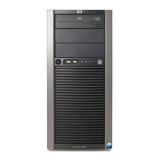
Page 58: Server Component Identification
Server component identification Front panel components Item Description Media bays (bezel blanks) Power On/Standby button Hard drive bays USB connectors (2) Bezel lock CD-ROM drive Server component identification 58... -
Page 59: Front Panel Leds And Buttons
Front panel LEDs and buttons Item Description Status CD-ROM drive ejector — button Power On/Standby button — Power On/Standby LED Green = System has AC power and is functioning Amber = System has AC power and is in standby mode Off = System has no AC power Hard drive activity LED Green = Hard drives are properly connected and functioning... - Page 60 Item Description Power supply connectors Mouse connector Keyboard connector Serial connector Video connector USB connectors (2) RJ-45 Ethernet connector RJ-45 connector (iLO 2) Parallel connector Server component identification 60...
-
Page 61: Rear Panel Leds
Rear panel LEDs • Model with a redundant hot-plug power supply Item Description Status NIC link LED On = Link Off = No link NIC activity LED Flashing = Activity Off = No activity Power good LED Green = Power good is on and functioning Off = Power supply is off •... -
Page 62: System Board Components
Item Description Status NIC link LED On = Link Off = No link NIC activity LED Flashing = Activity Off = No activity System board components Item Description Processor power connector Redundant power supply connector System power connector DIMM slot 4 (bank B) DIMM slot 3 (bank A) DIMM slot 2 (bank B) DIMM slot 1 (bank A) -
Page 63: System Maintenance Switch
Item Description PCI expansion slot 1 (PCI Express x1*) PCI expansion slot 2 (PCI-X, 64-bit/100-MHz) PCI expansion slot 3 (PCI-X, 64-bit/100-MHz) PCI expansion slot 4 (PCI Express x4**) System fan connector Optional serial port connector Processor * x8 PCI Express cards are supported, but will run at x1 speeds. ** x8 PCI Express cards are supported, but will run at x4 speeds. -
Page 64: System Board Leds
System board LEDs Item LED description Status PPM error Amber = PPM has failed Off = Normal DIMM 4 failure Amber = DIMM has failed or is missing Off = Normal DIMM 3 failure Amber = DIMM has failed or is missing Off = Normal DIMM 2 failure Amber = DIMM has failed or is missing... -
Page 65: System Leds And Internal Health Led Combinations
NOTE: The system management driver must be installed for the internal system health LED to provide pre-failure and warranty conditions. The front panel health LEDs indicate only the current hardware status. In some situations, HP SIM ("HP Insight Diagnostics" on page 56) may report server status differently than the health LEDs because the software tracks more system attributes. -
Page 66: Sas And Sata Device Numbers
System LED and Internal health Status color LED color Fan (Amber) A required fan has failed. SAS and SATA device numbers Hot-plug SATA or SAS hard drive LEDs Item LED description Status Fault/UID status Amber = Drive failure Flashing amber = Fault-process activity Blue = Unit identification is active Off = No fault-process activity Server component identification 66... -
Page 67: Fan Locations
Item LED description Status Online/Activity status Green = Drive activity Flashing green = High activity on the drive or drive is being configured as part of an array Off = No drive activity The hard drive activity LED will not illuminate if using SATA drives connected to the embedded storage device. -
Page 68: Specifications
Specifications Environmental specifications Specification Value Temperature range* Operating 10°C to 35°C (50°F to 95°F) Shipping -10°C to 60°C (14°F to 140°F) Maximum wet bulb temperature 28°C (82.4°F) Relative humidity (noncondensing)** Operating 20% to 80% Non-operating 20% to 90% * All temperature ratings shown are for sea level. An altitude derating of 1°C per 300 m (1.8°F per 1,000 ft) to 3048 m (10,000 ft) is applicable. - Page 69 Specification Value Maximum peak power 410 W (non-redundant non-hot- plug) 430 W (redundant hot-plug) * 100 to 127 VAC is required for 8 A; 200 to 240 VAC is required for 4 A. Specifications 69...
-
Page 70: Acronyms And Abbreviations
Acronyms and abbreviations DIMM dual inline memory module error checking and correcting iLO 2 Integrated Lights-Out 2 Integrated Management Log network interface controller NVRAM non-volatile memory PCI-X peripheral component interconnect extended POST Power-On Self Test processor power module ProLiant Support Pack RAID redundant array of inexpensive (or independent) disks RBSU... - Page 71 serial attached SCSI SATA serial ATA SCSI small computer system interface SDRAM synchronous dynamic RAM Systems Insight Manager unit identification Acronyms and abbreviations 71...
-
Page 72: Index
Array Diagnostic Utility (ADU) 55 Hard drive cage option 30 hard drive LEDs 66 health LEDs 59, 65 heatsink 37 battery 45 HP Insight Diagnostics 55, 56 buttons 58, 59 illustrated parts catalog 16 cables 53 iLO (Integrated Lights-Out) 59, 63 cabling 53... - Page 73 specifications, server 68 static electricity 23 network connector LEDs 61 system board 46, 62 NIC LEDs 59, 61 system board battery 45 system board components 45, 62 system board LEDs 64 system components 19 overtemperature LED 64 system fan air baffle 26 system fan module and holder 27 system maintenance switch 63 part numbers 16...
Need help?
Do you have a question about the ProLiant ML310 Generation 4 and is the answer not in the manual?
Questions and answers