Table of Contents
Advertisement
Quick Links
Download this manual
See also:
Operating Manual
PECO WavePRO
INSTALLATION GUIDE:
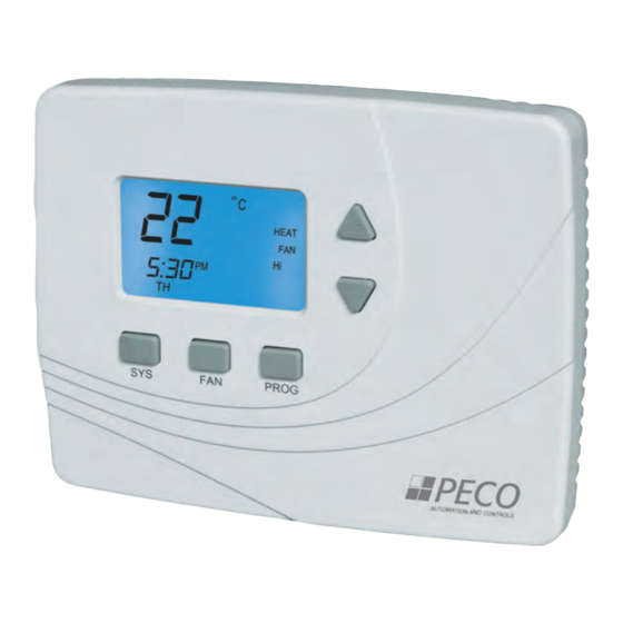
T2500 THERMOSTAT AND R2500 RECEIVER
Wireless control for up to 3-HEAT/ 2-COOL
heat pump and conventional systems
(gas,oil,electric).
Benefi ts:
• Reduced installation time
• Reduced wiring costs
• Energy cost savings
The Peco WavePRO Wireless System
The PECO WavePRO
receiver. It is designed for use with conventional (gas, oil, electric) or heat-pump
systems. It can support up 2-HEAT/ 2-COOL confi guration on conventional systems
and up to 3-HEAT/ 2-COOL confi gurations of heat pump systems. The PECO
WavePRO Wireless System is comprised of the wireless T2500 Thermostat paired with
the wireless R2500 Receiver.
The T2500 Thermostat may be powered by battery, 24 VAC, or by both
(recommended). The system may be programmed for 7-day individual, 5/2-day,
5/1/1-day, or 7-day identical programmable operation, with four time periods per day.
The R2500 Receiver is powered by 24 VAC only and is wired directly to the HVAC
equipment it controls.
™
Wireless System is a wireless thermostat transmitter and
™
Wireless System
• Scalability of network
• Flexibility in fl oor planning
• Ideal for building renovation
Advertisement
Table of Contents

Subscribe to Our Youtube Channel
Related Manuals for Peco WavePRO T2500


Summary of Contents for Peco WavePRO T2500
-
Page 1: The Peco Wavepro Wireless System
It is designed for use with conventional (gas, oil, electric) or heat-pump systems. It can support up 2-HEAT/ 2-COOL confi guration on conventional systems and up to 3-HEAT/ 2-COOL confi gurations of heat pump systems. The PECO WavePRO Wireless System is comprised of the wireless T2500 Thermostat paired with the wireless R2500 Receiver. -
Page 2: Table Of Contents
• Retain these instructions for future reference. When installed, this product will be part of an engineered system whose specifi cations and performance characteristics are not designed or controlled by PECO. You must review your application and national and local codes to assure that your installation will be functional and safe. -
Page 3: Getting Started
Two new AA batteries T2500 backplate PECO T2500 WavePRO Wireless Thermostat Wall anchors WavePRO Wireless System Installation Guide PECO R2500 Wireless WavePRO Wireless T2500 & Receiver R2500 Operating Manual © COPYRIGHT 2010 PECO, INC. ALL RIGHTS RESERVED. P/N 70161 3220-2216 Rev 0... -
Page 4: Install R2500 Receiver
CAUTION: Use copper wire only. Insulate or wire-nut all unused leads. • Use care to avoid electrostatic discharge to thermostat and receiver. Figure 3. Remove cover of R2500. © COPYRIGHT 2010 PECO, INC. ALL RIGHTS RESERVED. P/N 70161 3220-2216 Rev 0... -
Page 5: R2500 Wiring And Mounting Instructions
6. Cap off unused wires or terminate properly according to local building codes. 7. Re-attach the R2500 front cover (see Fig. 4). Figure 4 . Reattach cover of R2500 receiver. wiring passage © COPYRIGHT 2010 PECO, INC. ALL RIGHTS RESERVED. P/N 70161 3220-2216 Rev 0... -
Page 6: R2500 Wiring Examples
Some systems may have an economizer to help reduce energy use. An economizer is part of the air handling units (AHU) that enables the system to use outside air to help control interior zone temperatures. © COPYRIGHT 2010 PECO, INC. ALL RIGHTS RESERVED. P/N 70161 3220-2216 Rev 0... - Page 7 Emergency Economizer Economizer ALL ELECTRICAL LOADS MUST BE CONNECTED TO 24VAC 2. Note: If remote probe is used, please refer to the Terminal Designations Overview (p. 6). © COPYRIGHT 2010 PECO, INC. ALL RIGHTS RESERVED. P/N 70161 3220-2216 Rev 0...
- Page 8 Aux heat/Emergency Economizer Economizer ALL ELECTRICAL LOADS MUST BE CONNECTED TO 24VAC 2. Note: If remote probe is used, please refer to the Terminal Designations Overview. (p.w 6). © COPYRIGHT 2010 PECO, INC. ALL RIGHTS RESERVED. P/N 70161 3220-2216 Rev 0...
-
Page 9: Install The T2500 Thermostat Backplate
5. Remove backplate from the wall after all wires are labeled. If old thermostat has a wall mounting plate, remove both of these as an assembly. Figure 7. Label exposed wires. © COPYRIGHT 2010 PECO, INC. ALL RIGHTS RESERVED. P/N 70161 3220-2216 Rev 0... - Page 10 4. Tighten each terminal block screw until the wires are held fi rmly in place. Ensure that no uninsulated wire is exposed. Figure 9. 24VAC 1 24VAC 2 T2500 backplate with terminal block. © COPYRIGHT 2010 PECO, INC. ALL RIGHTS RESERVED. P/N 70161 3220-2216 Rev 0...
-
Page 11: Install Batteries In The T2500
Hold the T2500 Thermostat within 6-10 feet (3 m.) of the R2500 Receiver during pairing. • Step 3 (below) must be completed within two (2) minutes of completing Step 2, initiating the fl ashing LEDs on the R2500. © COPYRIGHT 2010 PECO, INC. ALL RIGHTS RESERVED. P/N 70161 3220-2216 Rev 0... - Page 12 Note: FAN has now been reset to AUTO. 5. Allow the device to time out. Wireless verifi cation is complete. For further system testing, see also “Advanced confi guration,” Menus 80-83. © COPYRIGHT 2010 PECO, INC. ALL RIGHTS RESERVED. P/N 70161 3220-2216 Rev 0...
-
Page 13: Mount The T2500 Onto The Backplate
Figure 13. Mount thermostat onto backplate (reverse view). Figure 12. Mount thermostat onto backplate (frontal view). Use retaining screw shown here. © COPYRIGHT 2010 PECO, INC. ALL RIGHTS RESERVED. P/N 70161 3220-2216 Rev 0... -
Page 14: Advanced Confi Guration: T2500 Thermostat
58-90 °F / 10-28 °C Selection:_________ Zone Temperature Offset: Select temperature display value; value may differ from actual zone temperature Menu Default: 0°F Options: +/- 9°F, +/- 4.5°C Selection:_________ © COPYRIGHT 2010 PECO, INC. ALL RIGHTS RESERVED. P/N 70161 3220-2216 Rev 0... - Page 15 Cycles Per Hour (CPH) for Cool Stage 1: Select Cycles Per Hour for Cool Stage 1; 0 disables cycling and thermostat becomes an ON/OFF control Menu Default: 3 CPH Options: 0 to 6 CPH Selection:_________ © COPYRIGHT 2010 PECO, INC. ALL RIGHTS RESERVED. P/N 70161 3220-2216 Rev 0...
- Page 16 Options 0, 1 Selection:_________ Intermittent Fan On Time: Minutes the fan will be on when intermittent fan is enabled Menu Default: 5 min. Options: 1-60 min. Selection:_________ © COPYRIGHT 2010 PECO, INC. ALL RIGHTS RESERVED. P/N 70161 3220-2216 Rev 0...
- Page 17 1=Gas (No fan with heat) Default: 0 Options: 0, 1 Selection:_________ Temporary Occupied Duration Limit Menu 0=No limit 1=One hour 2=Two hour 3=Three hour 4=Four hour Default: 3 Options: Selection:_________ © COPYRIGHT 2010 PECO, INC. ALL RIGHTS RESERVED. P/N 70161 3220-2216 Rev 0...
- Page 18 Options: System Test Fan Menu 0=Fan output off 1=Fan output active Default: 0 Options: System Test Economizer Menu 0=Economizer output off 1=Economizer output active Default: 0 Options: © COPYRIGHT 2010 PECO, INC. ALL RIGHTS RESERVED. P/N 70161 3220-2216 Rev 0...
-
Page 19: Frequently Asked Questions & Troubleshooting
• Turn off power to R2500 Receiver. Remove cover and verify same time (or heat does not wiring. turn off) © COPYRIGHT 2010 PECO, INC. ALL RIGHTS RESERVED. P/N 70161 3220-2216 Rev 0... -
Page 20: Product Specifi Cations
PO Box 82189, Portland, OR 97282 www.pecomanufacturing.com © COPYRIGHT 2010 PECO, INC. ALL RIGHTS RESERVED. P/N 70161 3220-2216 Rev 0 WavePRO is a trademark, and PECO is a registered trademark of PECO, Inc. The PECO logo is a trademark or servicemark of PECO, Inc.
Need help?
Do you have a question about the WavePRO T2500 and is the answer not in the manual?
Questions and answers