Table of Contents
Advertisement
Quick Links
the Peco PerFormance Pro thermostat
®
Thank you for choosing a PECO
Performance PRO™ thermostat. The Performance
PRO T8000 Series is intended for use in residential and commercial environments. It
is designed for and can support up to 3-HEAT/ 2-COOL confi gurations in conventional
systems and in heat pump applications. The Performance PRO also provides the
capability to meet the requirements for ASHRAE 90.1-2004 and California Building Code
Title 24 (2008 edition).
The Performance PRO T8000 Series is comprised of the T8000 non-programmable
thermostat models and the T8500 programmable thermostat models. The T8000 Series
features an 8 square inch blue backlit display with dynamic menus, accessed using soft
keys. All Performance PRO T8000 Series offer the following standard features: auto-
changeover, temporary override, optional remote sensors, occupancy sensors, three
levels of keypad lockout, a PIN access code, a furnace fi lter change reminder, and a heat/
cool Demand Indicator. In addition, the T8500 programmable models contain: up to four
scheduled events per day, a 365-day calendar, 20 holidays, holiday override, temporary
override, a Power Harvesting feature to preserve battery life (also known as "power
stealing"), Secure Digital (SD) card capability (card not included), and optional humidity
control (T8532-IAQ only).
The T8000 Series can be powered by 24 VAC or batteries or both (recommended). The
T8000 Series can control up to 7 outputs and monitor three external sensors. The T8000
Series mounts onto any PECO Performance PRO Series wallplate.
aPPlIcatIons anD FeatUres
The PECO Performance PRO thermostat is intended for use in conventional and heat
pump applications.
• System mode selections: Off-Heat-Cool-Auto-Emergency
• Stages: 1 Heat/1 Cool, 2 Heat/1 Cool, 1 Heat/2 Cool; 2 Heat/ 2 Cool; 3 Heat/ /2 Cool
• Fan control: Cycling (Auto) or Continuous (On); 1 Speed
• Permanent memory: All device settings are stored in permanent memory.
• Connections for Remote Sensors (indoor, outdoor, and occupancy)
• SD card capability (card not included)
▲
!
caUtIon!
• 24 vac low-voltage thermostat. Do not install on voltages higher than 30 vac.
• Use copper wire only; insulate or cap off (with wire nuts) all unused leads.
• Use care to avoid electrostatic discharge to the thermostat.
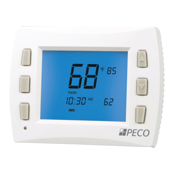
Front Panel reFerence: t8000/t8500 controls & DIsPlaY
Digital display with blue backlight
Current day
Temperature
(indoor)
System key
Fan key
More key
Current time
Demand
Figure 1. T8000/T8500 Thermostat
indicator
Mounting holes
Wiring passage
Figure 2. T8000/T8500 Thermostat
back view (with wallplate attached).
© COPYRIGHT 2010 PECO, INC. ALL RIGHTS RESERVED.
Fan (On/Auto)
Recovery mode
Setpoint
temperature
Up and Down
keys ▲/ ▼
System Mode
Override key
Keypad Lockout,
Battery Indicator,
Service
Indicator,
SD Card
(Home Display)
Mounting holes
PerFormance Pro t8000 serIes
InstallatIon GUIDe
▲
warnInG
!
• READ THESE INSTRUCTIONS CAREFULLY BEFORE ATTEMPTING TO INSTALL,
OPERATE OR SERVICE THIS THERMOSTAT.
• Failure to observe safety information and comply with instructions could result in
PERSONAL INJURY, DEATH AND/OR PROPERTY DAMAGE.
• To avoid electrical shock or damage to equipment, disconnect power before
installing or servicing and use only wiring with insulation rated for full thermostat
operating voltage.
• To avoid potential fi re and/or explosion do not use in potentially fl ammable or
explosive atmospheres.
• Retain these instructions for future reference.
• This product, when installed, will be part of an engineered system whose
specifi cations and performance characteristics are not designed or controlled
by PECO. Review applications and national and local codes to assure that the
installation will be functional and safe.
ProDUct sPecIFIcatIons
Temperature Control
Range:
50° to 90° F (10° to 32° C)
Differential:
1° F (0.5°C)
Input Power:
24 VAC (20-30 VAC) 50/60 Hz (+/- 10%) or AA alkaline batteries
(both recommended); 5mm terminals accept 14-24 AWG
stranded or solid wire.
Operating Temperature: 0° to 120°F (-17° to 48°C)
Shipping Temperature: -20° to 130°F (-28° to 54°C)
Operating Humidity:
5% to 95% RH, non-condensing
Physical Dimensions:
T8000/T8500 Thermostat: 4.3" H x 5.7" W x 1.3"D
with 3.2" x 2.5" / 8 square inch liquid crystal display (LCD)
Output Ratings
Voltage (50/60 Hz):
20-30 VAC
Current:
0.02-1.0 A per terminal; W1 (B/O), W2 (AUX), G, A, E, Y1, Y2.
Note: Collectively, total current draw must not exceed 2.5 A.
InstallatIon InstrUctIons
Select an appropriate thermostat location
Locate the thermostat about four feet (1.2m) above the fl oor on a wall in an area with good
ventilation and an average temperature, where it will be responsive to changes in room
temperature.
The Performance PRO T8000 Series may be mounted on a:
• Horizontal or vertical 2" X 4" device box
• Horizontal 4" X 4" device box
• Flat surface
Do not locate the thermostat where it can be affected by:
• Direct sunlight
• Drafts or dead areas behind doors
• Radiant heat from appliances
• Concealed pipes or chimneys
• Outside walls or unheated/uncooled areas
Required components (not included, unless otherwise specifi ed):
• Two new AA batteries (included)
• Screws and wall anchors (included)
• Screwdrivers: Phillips (for wallplate); small fl athead (for terminal blocks)
• Drill with 3/16" drill bit (or 7/32" for plaster)
• Wirecutter and stripper
• Level
• Performance PRO T8000 Series Thermostat (included)
• Performance PRO T8000 Series Thermostat Operating Manual (included)
i
note: secure Digital (sD) card feature (card not included) is a quick
confi guration tool to transfer customized settings to or from the thermostat.
For instructions, see "load sD card settings" in the operating manual.
1
P/N 70478 3220-2267 REV 00
Advertisement
Table of Contents

Subscribe to Our Youtube Channel
Related Manuals for Peco T8000 series


Summary of Contents for Peco T8000 series
-
Page 1: Installation Guide
ProDUct sPecIFIcatIons control (T8532-IAQ only). Temperature Control The T8000 Series can be powered by 24 VAC or batteries or both (recommended). The Range: 50° to 90° F (10° to 32° C) T8000 Series can control up to 7 outputs and monitor three external sensors. The T8000 Differential: 1°... - Page 2 Occupancy Setback Input sensor mUst Be connecteD to Power for Heating Power for Heating applications. termInal c (24 vac). Power for Cooling Power for Cooling © COPYRIGHT 2010 PECO, INC. ALL RIGHTS RESERVED. P/N 70478 3220-2267 REV 00...
- Page 3 Part vII: PerForm aDvanceD conFIGUratIon Power options The T8000 Series will operate on 24VAC power and/or two AA batteries (both are Perform advanced confi guration before attaching the thermostat to the wallplate. recommended). Choose from three methods to connect power to the thermostat.
- Page 4 Next. additional system tests include (see table 2): 600, system test main output (cool); 630, system test emergency output; 640, system test economizer © COPYRIGHT 2010 PECO, INC. ALL RIGHTS RESERVED. P/N 70413 3220-2260 REV 01...
- Page 5 Backlight Backlight temporarily on Backlight always on (low intensity, 24V only) Remote Sensor Select sensor if used. Contact PECO for information on the T8000 Series Indoor Remote Zone Sensor. No Sensor Indoor Sensor Outdoor Sensor display only Outdoor Sensor display and lockout control...
- Page 6 5 CPH Defines the number of cycles per hour for heating (Stage 2). Select 0 to enable ON-OFF control for (CPH) Heating Stage 2 heating. Stage 2 © COPYRIGHT 2010 PECO, INC. ALL RIGHTS RESERVED. P/N 70478 3220-2267 REV 00...
- Page 7 Select 1 to activate the Economizer output for 10 minutes; select 0, Done or a different Service Menu to disable. Economizer Disable Economizer Output Enable Economizer Output © COPYRIGHT 2010 PECO, INC. ALL RIGHTS RESERVED. P/N 70478 3220-2267 REV 00...
- Page 8 • An error has occurred • Check remote sensor wiring. • Remote sensor may be malfunctioning • Verify that the sensor(s) are PECO supported products. If heat pump issues cool air in heat mode or warm air • Changeover valve (B/O terminal) is not •...
- Page 9 PIn access code, and keep it in a safe place. note: Use appropriate wire for outdoor use. locate & moUnt Peco occUPancY sensor (sB200-001) Figure 16. Please use the installation instructions for the SB200-001 to mount the PECO Occupancy Service Menu Sensor SB200-001. 342 allows user to create...
-
Page 10: Installation
• This product, when installed, will be part of an engineered system whose specifi cations and performance characteristics are not designed or controlled by PECO. Review applications and national and local codes to assure that the installation will be functional and safe. - Page 11 • Make sure to select “01” in Service Menu 170. locate & moUnt Peco oUtDoor remote sensor Following are instructions on the PECO Outdoor Remote Sensor (P/N 70327). Mount the sensor where: • It can measure true outdoor ambient temperature •...
-
Page 12: Temperature Sensor
ON (Cycles with demand) Cooling © COPYRIGHT 2010 PECO, INC. ALL RIGHTS RESERVED. P/N 70478 3220-2267 REV 00 Performance PRO is a trademark, and PECO is a registered trademark of PECO, Inc. The PECO logo is a trademark or servicemark of PECO, Inc.
Need help?
Do you have a question about the T8000 series and is the answer not in the manual?
Questions and answers