Peco RW205 Installation Manual
Wave wireless system thermostat and receiver
Hide thumbs
Also See for RW205:
- Operating manual (24 pages) ,
- Installation instructions manual (11 pages) ,
- Owner's manual (24 pages)
Advertisement
Available languages
Available languages
Quick Links
Download this manual
See also:
Operating Manual
THE PECO
WAVE WIRELESS
®
®
The PECO Wave Wireless System is comprised of the wireless TW205 or TW206
Thermostat paired with a RW205 Receiver. Optional accessories to the System are the
SW205 wireless occupancy sensor and/or SW206 wireless door switch. This installation
guide explains how to install the RW205 Receiver, the TW205/TW206 Thermostat, and
select optional accessories.
The TW205 and TW206 can be powered by 24 VAC, batteries, or by both (recommended).
The TW205 and TW206 both feature wireless communication with the RW205 Receiver.
The TW205 Thermostat is non-programmable digital model. The TW205 features a
single setpoint with deadband, auto changeover, and fan control functions. The TW206
Thermostat is the programmable digital model. The TW206 can be programmed for 7-day
individual, 5/2-day, 5/1/1-day, or 7-day identical programmable operation, with four time
periods per day. The TW206 also features separate heating and cooling setpoints, auto
changeover, and fan control functions.
The RW205 Receiver is wired to the HVAC equipment and controls all outputs. The
optional SW205 occupancy sensor and SW206 door switch also communicate wirelessly
with the RW205 Receiver to signal occupancy status.
APPLICATIONS AND FEATURES
The PECO Wave Wireless System is intended for use in PTAC, PTHP, fan coil, and heat
pump applications.
• System mode selections: Off-Heat-Cool-Auto-Setback
• Stages: 1 Heat/1 Cool, 2 Heat/1 Cool, 1 Heat/2 Cool
• 6 outputs (RW205): 1 Heat, 1 Cool, Up to 3 Fan, Outside Air Damper / Reversing Valve
• Fan control: 1-3 Speeds, Cycling (Auto) or Continuous (On)
• Permanent memory: The thermostat does not need batteries to store user-confi gured
settings in memory. Nonvolatile memory (EEPROM) saves temperature setpoints, fan,
and system settings for unlimited time.
• Connections for Remote Temperature Probe and Setback (RW205)
▲
CAUTION
!
• Use copper wire only; insulate or wire nut all unused leads.
• Use care to avoid electrostatic discharge to the thermostat and receiver.
• In order to establish correct pairing, the RW205 must be mounted and wired before
applying power to the TW205/TW206.
• Read and understand "Table 1. Advanced Confi guration Service Menus" to
determine preferred settings on TW205/TW206 before performing wireless pairing.
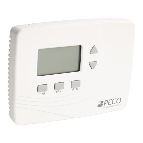
FRONT PANEL REFERENCE
Liquid crystal
display (LCD)
with blue
backlight
System button
FAN button
Figure 1: TW205 Thermostat.
Device connection LED indicator lights
CONNECT
button.
Figure 2. RW205 Receiver:
LED indicators and CONNECT button.
© COPYRIGHT 2010 PECO, INC. ALL RIGHTS RESERVED.
WAVE WIRELESS SYSTEM TW205-TW206 & RW205
THERMOSTAT AND RECEIVER INSTALLATION
SYSTEM
Fahrenheit/ Celsius
temperature display
button (TW205) or
Program button
(TW206)
Voltage selection switch
(up position is 24V;
down position is
110V/ 277V)
2 3 4 5 6 7 8
1
Terminals
Figure 3. RW205 Receiver with
front cover removed.
▲
WARNING
!
• READ THESE INSTRUCTIONS CAREFULLY BEFORE ATTEMPTING TO INSTALL,
OPERATE OR SERVICE THIS THERMOSTAT OR RECEIVER.
• Before installing this control, the RW205 Voltage Selection Switch must be placed
in the correct position. See instructions.
• Failure to observe safety information and comply with instructions could result in
PERSONAL INJURY, DEATH AND/OR PROPERTY DAMAGE.
• To avoid electrical shock or damage to equipment, disconnect power before installing
or servicing and use only wiring with insulation rated for full thermostat operating
voltage.
• To avoid potential fi re and/or explosion do not use in potentially fl ammable or explo-
sive atmospheres.
• Retain these instructions for future reference. This product, when installed, will be
part of an engineered system whose specifi cations and performance characteristics
are not designed or controlled by PECO. You must review your application and
national and local codes to assure that your installation will be functional and safe.
SPECIFICATIONS
Temperature Range:
50° to 90°F (10° to 32°C)
Differential:
1°F (0.5°C)
Input Power:
TW205 / TW206 Thermostat: Two AA alkaline batteries
or 24 VAC, 50/60 Hz.
RW205 Receiver: 24 VAC or 100-277 VAC, 50/60 Hz
RW205 Receiver Output Rating: 24 VA (pilot duty)
Wireless Type:
902 to 928 MHz Band, FHSS
(Frequency Hopping Spread Spectrum)
Wireless Range:
100 ft minimum in open air
Operating Temperature: 0° to 120°F (-17° to 48°C)
Shipping Temperature: -20° to 130°F (-28° to 54°C)
Operating Humidity:
5% to 95% RH, non-condensing
Physical Dimensions:
TW205 / TW206: 4.5"H x 5.75"W x 1.1"D
RW205: 4.8"H x 3.8"W x 1.3"D
Wave Wireless System complies with Part 15 of FCC guidelines (see Operating Manual).
RW205 OUTPUT RATINGS:
RATINGS
RES
VOLTAGE
AMPS
FLA
LRA
24 VAC
NA
NA
NA
120 VAC
5.8
34.8
6.0
240 VAC
2.9
17.4
5.0
277 VAC
2.4
14.4
4.2
COMBINED LOAD CURRENT NOT TO EXCEED 20 AMPS
INSTALLATION: WAVE WIRELESS SYSTEM
Mounting Considerations for Wave Wireless System
When selecting mounting locations for Wave Wireless System components, it is important
to consider the number and types of obstructions between components. The Wave
Wireless System will communicate through walls and other obstructions, but they will
reduce the effective operating range of these devices. The effectiveness of the Wave
Wireless System will be greatly reduced if it is mounted within a metal enclosure. The
Wave Wireless System uses frequency-hopping technology to improve its resistance to
wireless interference; however, malfunctioning or improperly used wireless devices may
interfere with the Wave Wireless System. Take note of any other wireless devices in use
near the Wave Wireless System before installation or if communication errors occur.
• Locate TW205/TW206 and RW205 within 100 ft. (30 m.) of one another for optimal
operation.
• Choose indoor mounting locations free from obstructions; avoid locating devices within a
metal enclosure or between large obstructions.
Mounting Confi guration, RW205
The RW205 may be mounted:
• on a vertical 2" X 4" device box
• on a fl at surface
• using a fl ush mount (Optional: See PECO Web site for PTAC Cutout Template.)
Required components (tools not included):
• Two new AA batteries (included)
• RW205 Receiver
• TW205/TW206 Thermostat
• PECO Wave Wireless System Operating Manual
1
PILOT
HP
DUTY
24 VA
NA
125 VA
1/4
125 VA
1/4
125 VA
1/4
P/N 70218 3220-2230 REV 0
Advertisement

Subscribe to Our Youtube Channel
Related Manuals for Peco RW205


Summary of Contents for Peco RW205
- Page 1 Temperature Range: 50° to 90°F (10° to 32°C) Differential: 1°F (0.5°C) The PECO Wave Wireless System is intended for use in PTAC, PTHP, fan coil, and heat Input Power: TW205 / TW206 Thermostat: Two AA alkaline batteries pump applications. or 24 VAC, 50/60 Hz.
- Page 2 ▲ PART I: RW205 RECEIVER WIRING AND MOUNTING WARNING: DO NOT connect the following optional accessories to high voltage/24VAC circuits. Figure 4. These optional accessories are also available from PECO. RW205 Receiver PECO Optional Accessories RW205 backplate and mounting screws.
- Page 3 Wireless System. If you are only attempting to add a SW205 occupancy sensor batteries from the Insert two AA or SW206 door switch to an existing PECO Wave Wireless System, a 5-second TW205/TW206. When batteries into connection process can be performed. Hold down the CONNECT button until the power is restored, reverse side.
- Page 4 Defi nes the duration in which fan will be off. Fan Off Time will be activated after Fan On Time has passed. © COPYRIGHT 2010 PECO, INC. ALL RIGHTS RESERVED. P/N 70218 3220-2230 REV 0 PECO Wave Wireless and PECO are registered trademarks of PECO, Inc. The PECO logo is a trademark of PECO, Inc.
- Page 5 24V; la • sobre una superfi cie plana conexión del posición hacia abajo • utilizando un montaje empotrado (Opcional: Visite el sitio Web de PECO para ver la dispositivo es de 110V/ 277V) plantilla de corte de PTAC.) 2 3 4 5 6 7 8 Componentes necesarios (las herramientas no están incluidas):...
- Page 6 NOTA: TODAS LAS CARGAS ELÉCTRICAS SE DEBEN CONECTAR A L2. 11. Quite el aislamiento de cada cable a una distancia apropiada (cerca de 1/4” o 64 cm). © COPYRIGHT 2010 PECO, INC. TODOS LOS DERECHOS RESERVADOS. P/N 70218 3220-2230 REV 0...
- Page 7 SW205 o un interruptor de puerta SW206 a un Sistema de PARTE IV: CONFIGURACIÓN AVANZADA Onda Inalámbrica PECO existente, se puede realizar un proceso de conexión de 5 segundos. Mantenga presionado en botón CONNECT (conectar) hasta que Realice la confi...
- Page 8 © COPYRIGHT 2010 PECO, INC. TODOS LOS DERECHOS RESERVADOS. P/N 70218 3220-2230 REV 0 PECO Wave Wireless y PECO son marcas registradas de PECO, Inc. El logo de PECO es una marca registrada de PECO, Inc.
-
Page 9: Spécifications
24 V, la position • sur une surface plane inférieure, au • en recourant à un montage encastré (facultatif : consulter le site Web PECO pour le 2 3 4 5 6 7 8 110 V/277 V) modèle de découpe PTAC.) - Page 10 AVERTISSEMENT : NE PAS raccorder les accessoires facultatifs suivants sur la tension de secteur ou de 24 Vc.a. Figure 4. Les accessoires facultatifs sont également disponibles auprès de PECO. Plaque murale et Accessoires facultatifs PECO du récepteur RW205 vis de montage du récepteur RW205.
- Page 11 • Le témoin DEL « Thermostat » du récepteur RW205 est allumé en permanence. et les fonctions des touches, veuillez faire référence au « Guide d’emploi du système PECO • L’indicateur de service du thermostat TW205/TW206 disparaît de l’affi chage.
- Page 12 fi n de la période d’arrêt du ventilateur. © COPYRIGHT 2010 PECO, INC. TOUS DROITS RÉSERVÉS. P/N 70218 3220-2230 REV 0 PECO Wave Wireless et PECO sont des marques déposées de PECO, Inc. Le logo PECO est une marque de commerce de PECO, Inc.
Need help?
Do you have a question about the RW205 and is the answer not in the manual?
Questions and answers