Table of Contents
Advertisement
Quick Links
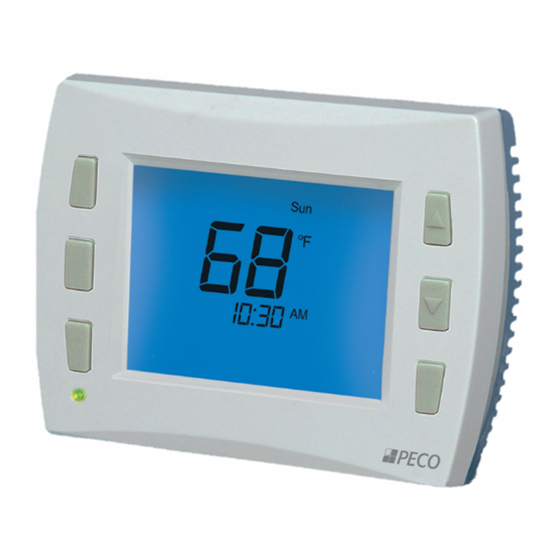
PECO TW180 THERMOSTAT
Thank you for choosing a PECO
®
is intended for use in commercial and residential enviroments. It supports both
programmable and non-programmable operation.
Key features include: auto-changeover; optional remote sensor; three levels of
Keypad Lockout with optional PIN access code; a heat/cool Demand Indicator;
up to four scheduled events per day, a 365-day calendar, 20 holidays, holiday
override and temporary override.
Applications
The PECO
TW180 applications include fan coil, PTAC and conventional
®
system with a single or multi speed fan operation.
System Mode Selections: Off-Heat-Cool-Auto
Outputs: 1 Cool and up to 2 Heat
Fan Control: Cycling (Auto) or Continuous (On); Up to 3 Speeds or Staged
Permanent Memory: All device settings are stored in permanent memory.
Optional Connections: Remote Sensor, Pipe Sensor, Fault Detection,
Setback, Occupancy and Door Switch
OUTPUT RATINGS
Inductive
!
Voltage
FLA
LRA
24 VAC
NA
120 VAC
4.4
26.4
240 VAC
2.2
13.2
277 VAC
1.8
10.8
COMBINED LOAD CURRENT NOT TO EXCEED 20 AMPS
MOUNT ONLY TO A GROUNDED METALLIC BOX
LOW VOLTAGE WIRING IS CLASS 2
120-277 VAC Operation
TB2-1
Unused
Input Power Jumper
TB2-2
for 120-277 VAC Operation.
TB2-3
Black
(Switched Side)
Yellow
Red
Blue
White/Orange
White/Red
White/Brown
Brown
Unused
TB1-1
Unused
TB1-2
Remote Temperature Sensor
TB1-3
Pipe Sensor
TB1-4
Occupancy
TB1-5
Door/ Window Switch
TB1-6
Sensor Common
TB1-7
© COPYRIGHT 2023 PECO, INC. ALL RIGHTS RESERVED.
CONTROL
SYSTEMS
TW180 thermostat. The TW180 thermostat
Resistive
Pilot Duty
Amps
NA
NA
24 VA
4.5
125 VA
4.3
125 VA
4.2
125 VA
Wiring Diagram
(Default Postion)
L1 HOT
L2 Neutral
HEAT 1
COOL
FAN HI
CAUTION
Individually wirenut
FAN MED
off unused leads
FAN LO
Outside Air
or HEAT 2
Installation INSTRUCTION
▲
!
• READ THESE INSTRUCTIONS CAREFULLY BEFORE ATTEMPTING TO
INSTALL, OPERATE OR SERVICE THIS THERMOSTAT.
• Failure to observe safety information and comply with instructions could
result in PERSONAL INJURY, DEATH AND/OR PROPERTY DAMAGE.
• To avoid electrical shock or damage to equipment, disconnect power
before installing or servicing and use only wiring with insulation rated for full
thermostat operating voltage.
• Use care to avoid electrostatic discharge.
• To avoid potential fire and/or explosion do not use in potentially flammable
or explosive atmospheres.
• Retain these instructions for future reference.
• This product, when installed, will be part of an engineered system whose
specifications and performance characteristics are not designed or
controlled by PECO
. Review applications and national and local codes to
®
assure that the installation will be functional and safe.
SPECIFICATIONS
Temperature Control Range: 50 to 90°F (10 to 32°C
Differential: 1°F
Physical Dimensions: 4.4"H x 5.8"W x 1.1"D
Construction of Control: Independently Mounted
Operating Temperature: 0°F to 120°F (-18° to 49°C)
Shipping/Storage Temperature: -20°F to 130°F (-29°C to 54°C)
Operating Humidity: 5%-95% RH, non-condensing
Low Voltage Terminal Connections: 18 -12 AWG
Remote Sensor: 10K NTC Type 2
Agency Approvals: UL, UL Canada
24 VAC Operation
MOVE Input Power Jumper
TB2-1
to TB2-1 and TB2-2
TB2-2
for 24 VAC Operation.
TB2-3
Black
Yellow
Red
HEAT 1
Blue
COOL
White/Orange
FAN HI
White/Red
FAN MED
White/Brown
FAN LO
Brown
Outside Air
or HEAT 2
24 VAC 1
(Switched Side)
TB1-1
24 VAC 2
TB1-2
Remote Temperature Sensor
TB1-3
Pipe Sensor
TB1-4
Occupancy
TB1-5
Door/ Window Switch
TB1-6
Sensor Common
TB1-7
1
TW180 THERMOSTAT
WARNING
CAUTION
Individually wirenut
off unused leads
P/N 74150 3220-2384 REV 04
Advertisement
Table of Contents

Subscribe to Our Youtube Channel
Related Manuals for Peco TW180


Summary of Contents for Peco TW180
- Page 1 • Use care to avoid electrostatic discharge. Applications • To avoid potential fire and/or explosion do not use in potentially flammable The PECO TW180 applications include fan coil, PTAC and conventional ® or explosive atmospheres. system with a single or multi speed fan operation.
- Page 2 This will release the four side latches. 11. Turn on power to equipment. © COPYRIGHT 2023 PECO, INC. ALL RIGHTS RESERVED. P/N 74150 3220-2384 REV 04...
- Page 3 - Once the door closes, if no occupancy signal is detected within 2 minutes, the TW180 will go into setback. - If occupancy is detected any time after the door closes, the TW180 is set to occupied mode until the door is opened again.
- Page 4 Pipe Sensor 0 = Disabled (Default) Enables fan coil pipe sensor operation. Connect a PECO pipe sensor or dry switch closure for change over from Summer (cold water) to Winter (hot water) on COOL output (blue 1 = Two Pipe Operation wire).
- Page 5 1 = Closed when door is closed Number of Program Events 2 or 4 Events (DEFAULT = 2) When the TW180 is set up as programmable this sets the number of events per day. Events are OCC1, UNOCC1, OCC2, UNOCC2...
- Page 6 0 = Time, Temp, SP (Default) Icons that will be displayed in the default state. 1 = Time, Temp NOTE: Setpoint will not be displayed if TW180 System Mode is OFF. 2 = Time 3 = Temp 4 = None...
- Page 7 10 minutes. The outputs will automatically turn on. 1 = Enable HI Fan Output 2 = Enable MED Fan Output 3 = Enable LO Fan Output © COPYRIGHT 2023 PECO, INC. ALL RIGHTS RESERVED. P/N 74150 3220-2384 REV 04...
- Page 8 • If using a remote sensor, verify probe wiring and type. UL60730-1 Required Information: Purpose of control: Operating Control,Room Thermostat Type 1.C Action Pollution Degree 2 Impulse Voltage: 2500 V © COPYRIGHT 2023 PECO, INC. ALL RIGHTS RESERVED. P/N 74150 3220-2384 REV 04...
Need help?
Do you have a question about the TW180 and is the answer not in the manual?
Questions and answers