Table of Contents
Advertisement
Quick Links
Download this manual
See also:
Setup Manual
Advertisement
Table of Contents

Related Manuals for Extron electronics FOX DA8 Plus


Summary of Contents for Extron electronics FOX DA8 Plus
- Page 1 User Guide Distribution Amplifiers FOX DA8 Plus Eight Output Fiber Optic Distribution Amplifier 68-2145-01 Rev. A 07 11...
- Page 2 Safety Instructions • English Warning Power sources • This equipment should be operated only from the power source indicated on the product. This This symbol is intended to alert the user of important operating and mainte- equipment is intended to be used with a main power system with a grounded (neutral) conductor. The third nance (servicing) instructions in the literature provided with the equipment.
- Page 3 FCC Class A Notice This equipment has been tested and found to comply with the limits for a Class A digital device, pursuant to part 15 of the FCC Rules. Operation is subject to the following two conditions: This device may not cause harmful interference. This device must accept any interference received, including interference that may cause undesired operation.
-
Page 4: Conventions Used In This Guide
Selectable items, such as menu names, menu options, buttons, tabs, and field names are written in the font shown here: From the menu, select File Click the button. Copyright © 2011 Extron Electronics. All rights reserved. Trademarks All trademarks mentioned in this guide are the properties of their respective owners. -
Page 5: Table Of Contents
Contents Introduction ..........Reference Information ......About this Guide ..........1 Specifications ..........19 About the FOX DA8 Plus ........2 Part Numbers and Accessories ......21 Features ............3 FOX DA8 Part Numbers ......21 Included Parts ..........21 Optional Accessories ........ - Page 6 FOX DA8 Plus • Contents...
-
Page 7: Introduction
(DAs). The FOX DA8 Plus is available in two transmission modes that define the transmission range of the DA: FOX DA8 Plus MM — A 1-input, 8-output multimode DA, with a range of up to 2 km •... -
Page 8: About The Fox Da8 Plus
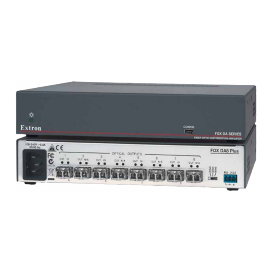
About the FOX DA8 Plus The FOX DA8 Plus product family consists of two products; a singlemode and a multimode ultra-high performance fiber optic distribution amplifier. The FOX DA8 Plus (see figure 1) accepts a proprietary input optical signal from a compatible Extron fiber optic transmitter (Tx) or other device. -
Page 9: Features
1900x1200 at 60 Hz. Higher resolutions can be transmitted, but with some loss of video quality. Optical input and outputs — The FOX DA8 Plus inputs and outputs the optical signal on LC video connectors. Active and individually isolated outputs — The FOX DA8 Plus uses active signal splitting to maintain equal transmitter power to all outputs, maximizing distance capabilities by ensuring full availability of optical loss budget for each output. -
Page 10: Installation And Operation
In this guide, the term “sending connector” refers to an LC connector on a device that outputs a fiber optic signal. The term “receiving connector” refers to an LC connector that receives an optical signal. FOX DA8 Plus • Installation and Operation... - Page 11 AC power connector — Plug a standard IEC power cord into this connector to connect the FOX DA8 Plus to a 100 VAC to 240 VAC, 50-60 Hz power source. Transmitter Input connectors and LEDs — OPTICAL NOTE: Input (right-hand) LC connectors marked with an asterisk (*)
- Page 12 This port is RS-232 only, with the following protocols: • 9600 baud • no parity • 8 data bits • 1 stop bit • no flow control FOX DA8 Plus • Installation and Operation...
-
Page 13: Front Panel Features
Power LED — This LED lights when power is applied to the unit. Config(uration) port — For USB control of the DA, connect a host device, such as a computer or touch panel control, via this mini USB B port. FOX DA8 Plus • Installation and Operation... -
Page 14: System Operation
System Operation After the transmitter, the FOX DA8 Plus, the receivers, and their connected devices are powered up, the system is fully operational. If any problems are encountered, ensure all traditional and fiber cables are routed and connected properly: •... -
Page 15: Remote Control
FOX Extenders Program Remote Control Ports The FOX DA8 Plus has two ports that can be connected to a host device such as a computer running the Extron DataViewer utility or the HyperTerminal utility, an RS-232 capable PDA, or a control system. These ports make remote control of the DA possible. The ports are: The rear panel RS-232 port —... -
Page 16: Simple Instruction Set ™ Control
(CR/LF = ] ), which signals the end of the response character string. A string is one or more characters. Start-up Message The FOX DA8 Plus issues the following copyright message when it first powers on. Vx.xx the firmware version number, is the part number. -
Page 17: Symbol Definitions
V01X08 shows the number of available Information request V01X08•A00X00 inputs (1) and outputs (8) for this product. A00X00 has no meaning for this product. Show firmware version Example: 1.23 The factory-installed controller firmware version is 1.23 (sample value only). FOX DA8 Plus • Remote Control... -
Page 18: Fox Extenders Program
Show DA configuration switch position FOX Extenders Control Program The Extron FOX Extenders Control Program, which communicates with the FOX DA8 Plus via the rear panel RS-232 port or front panel Configuration port of the unit, provides an easy way to control the DA mute function and set reclocker rates for the inputs. -
Page 19: Using The Program
“Simple Instruction Set™ Control” section. NOTE: You may need to repeat these steps if you subsequently connect the DA to a different USB port on the same computer. FOX DA8 Plus • Remote Control... - Page 20 TIP: If you change the configuration of the DA using the rear panel DA configuration DIP switch (item d in the “Installation and Operation” section), click the Refresh button ( ). This forces the FOX Extenders Control Program to show the new configuration. FOX DA8 Plus • Remote Control...
-
Page 21: Firmware Upgrade
Figure 11. Location of Firmware Upgrade Files Select the appropriate firmware file (FOX DA8 Plus) to download and click Download Enter the requested personal information and then click to copy the firmware Download to your computer. - Page 22 Click Finish to exit the program. NOTE: The name, version and file size shown are sample values only. Folder where firmware is installed Figure 12. Downloading Firmware Upgrade Files FOX DA8 Plus • Remote Control...
- Page 23 Update Firmware button ( ). The Extron Tools Update firmware Firmware Loader appears (see figure 13). Figure 13. Extron Firmware Loader Window Select the FOX DA8 Plus and click File > Open . The Choose Firmware File screen appears (see figure 14).
- Page 24 Once the status bars have progressed from 100% , and Status is listed as Completed , the firmware loader utility resets the DA. Figure 15. Firmware Loader Screen Click Exit to close the Firmware Loader. FOX DA8 Plus • Remote Control...
-
Page 25: Reference Information
Reference Information This section discusses the specifications, part numbers, and accessories for the FOX DA8 Plus. Topics that are covered include: Specifications • • Part Numbers and Accessories Mounting the Unit • Specifications Optical specifications NOTE: These amplifiers are class 1 laser products. They meet the safety regulations of IEC-60825, FDA 21 CFR 1040.10, and FDA 21 CFR 1040.11. - Page 26 EMI/EMC ......... CE, C-tick, FCC Class A, FDA Class 1, ICES, VCCI, MTBF ..........30,000 hours Warranty ........3 years parts and labor NOTES • All nominal levels are at ±10%. Specifications are subject to change without notice. • FOX DA8 Plus • Reference Information...
-
Page 27: Part Numbers And Accessories
USB CFG Cable USB A Male to USB Mini B Male Configuration Cable 26-654-06 Compatible Equipment The FOX DA8 Plus is compatible with the following Extron fiber optic devices: NOTE: Ensure that you match the transmission mode, singlemode or multimode, among all connected devices. -
Page 28: Fiber Cables
OM4 MM P/2K Plenum 2 km (6,562 foot) Spool 22-225-02 SM P/2K Plenum 2 km (6,562 foot) Spool 22-223-02 Fiber Optic Termination Kit Termination Kit 100-656-01 QLC MM/10 Multimode, qty. 10 101-018-01 QLC SM/10 Singlemode, qty. 10 101-017-01 FOX DA8 Plus • Reference Information... -
Page 29: Mounting The Unit
MBD 129 — Through desk mounting kit (part number 70-077-02) • Mount the FOX DA8 Plus in accordance with the instructions provided with the mounting kit. Rack mounting UL Guidelines The following Underwriters Laboratories (UL) guidelines pertain to the installation of the FOX DA8 into a rack. -
Page 30: Extron Warranty
Extron Electronics makes no further warranties either expressed or implied with respect to the product and its quality, performance, merchantability, or fitness for any particular use. In no event will Extron Electronics be liable for direct, indirect, or consequential damages resulting from any defect in this product even if Extron Electronics has been advised of such damage.
Need help?
Do you have a question about the FOX DA8 Plus and is the answer not in the manual?
Questions and answers