Advertisement
Table of Contents
- 1 Step 1 — Turn All of the Equipment off and Disconnect All Power Sources.
- 2 Step 2 — Mount the Amplifier in Either a Plenum Space, on a Rack, under a Desk, or on a Projector.
- 3 Step 4 — Attach Sources to the MPA 601 Unit from the Audio Source or Projector.
- 4 Step 5 — Connect Power Cords to the MPA 601 and Other Audio Equipment.
- 5 Step 6 — Adjust the MPA 601 Input LEVEL, BASS, and TREBLE from the Front Panel.
- Download this manual
V C G
CLASS 2 WIRING
REMOTE
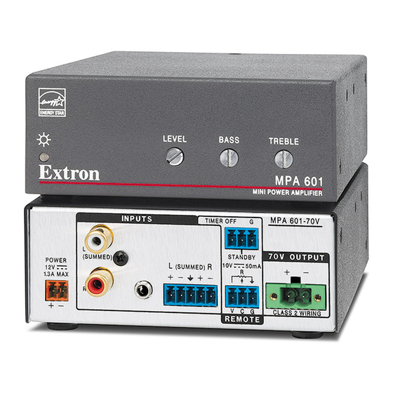
MPA 601-70V and MPA 601-100V • Setup Guide
This guide provides basic instructions for an experienced installer to install and configure the
Extron MPA 601-70V and MPA 601-100V mini power amplifiers. See below for front and back panel of the MPA 601-70V.
Step 1 — Turn all of the equipment off and disconnect all power sources.
Step 2 — Mount the amplifier in either a plenum space, on a rack, under a desk, or on a projector.
ATTENTION:
Although the amplifier is plenum rated, the power supply provided with it is not. The power supply must not be placed
•
in the plenum space. Cables to and from the amplifier must be plenum rated.
Bien que l'amplificateur soit conforme à la norme relative aux faux plafonds, la source d'alimentation fournie avec
•
ne l'est pas. La source d'alimentation ne doit pas être placée dans l'espace plenum. Les câbles depuis et vers
l'amplificateur doivent aussi être classés plenum.
Use only the two round mounting holes for mounting the MPA 601. The other four (hexagonal) holes anchor stand-offs
•
for the internal circuit boards. Using them may damage the amplifier and does not provide secure mounting for the
unit.
Utilisez seulement les deux trous pour monter le MPA 601. Les autres quatre trous d'ancrage sont destinés aux cartes
•
de circuit internes. Le fait de les utiliser pourrait endommager l'amplificateur et n'assurera pas un montage sécurisé
pour l'unité.
Step 3 — Attach the speakers to the MPA 601 using the 2-pole, 5 mm screw-lock captive screw speaker
receptacle on the rear panel.
ATTENTION:
Do not ground or short the speaker outputs as this will damage the amplifier.
•
Ne pas mettre à la terre ni créer de court-circuit dans les sorties de l'enceinte, afin d'éviter tout
•
risque de détérioration de l'amplificateur.
Step 4 — Attach sources to the MPA 601 unit from the audio source or projector.
The three rear panel audio inputs can be used individually or together:
•
One pair of RCA receptacles (unbalanced)
•
One 3.5 mm stereo tip-ring-sleeve receptacle (unbalanced)
•
One 3.5 mm, 5-pole captive screw receptacle (balanced or unbalanced)
Tip
Sleeve
Tip
Sleeve
Unbalanced Stereo Input
NOTES:
•
The MPA 601 amplifier sums the left and right signals from both the TRS and RCA
inputs to form Sum 1. Sum 1 is then weighted. At the same time, the amplifier sums the
left and right signals from the captive screw input to form Sum 2. Sum 1 and Sum 2 are
then summed together to form a single mono signal. Refer to the MPA 601 Series User
Guide for more details regarding audio summing.
•
The captive screw, RCA and TRS inputs are buffered.
Ensure the audio output of the projector is set to variable. Multiple input options can be used simultaneously and be summed.
LEVEL
BASS
TREBLE
MPA 601
MINI POWER AMPLIFIER
Tip
Ring
Sleeves
Tip
Ring
Balanced Stereo Input
INPUTS
TIMER OFF
L
(SUMMED)
POWER
L
R
(SUMMED)
12V
1.3A MAX
R
Tip (+)
Sleeve ( )
RCA Connector
Tip
Sleeve
Unbalanced Mono Input
INPUTS
MPA 601-70V
G
70V OUTPUT
STANDBY
10V
50mA
R
V C G
CLASS 2 WIRING
REMOTE
70V OUTPUT
CLASS 2 WIRING
Tip (L)
Ring (R)
Sleeve ( )
3.5 mm TRS Connector
Tip
Ring
Sleeve
Balanced Mono Input
INPUTS
L
(SUMMED)
POWER
L
(SUMMED)
12V
1.3A MAX
R
MPA 601-70V
TIMER OFF
G
MPA 6
G
70V O
STANDBY
10V
R
50mA
R
V C G
CLASS
REMOTE
1
Advertisement
Table of Contents

Subscribe to Our Youtube Channel
Related Manuals for Extron electronics MPA 601-70V


Summary of Contents for Extron electronics MPA 601-70V
- Page 1 MPA 601-70V and MPA 601-100V • Setup Guide This guide provides basic instructions for an experienced installer to install and configure the Extron MPA 601-70V and MPA 601-100V mini power amplifiers. See below for front and back panel of the MPA 601-70V. MPA 601-70V...
- Page 2 Extron USA - West Extron USA - East +1.714.491.1500 +1.919.850.1000 +31.33.453.4040 +91.80.3055.3777 +1.714.491.1517 FAX +1.919.850.1001 FAX +31.33.453.4050 FAX +91.80.3055.3737 FAX 68-2512-50 Rev. A © 2016 Extron Electronics All rights reserved. All trademarks mentioned are the property of their respective owners. www.extron.com 11 16...
Need help?
Do you have a question about the MPA 601-70V and is the answer not in the manual?
Questions and answers