Extron electronics XTRA Series User Manual
Half-rack audio
Hide thumbs
Also See for XTRA Series:
- User manual (29 pages) ,
- Setup manual (2 pages) ,
- User manual (23 pages)

Related Manuals for Extron electronics XTRA Series


Summary of Contents for Extron electronics XTRA Series
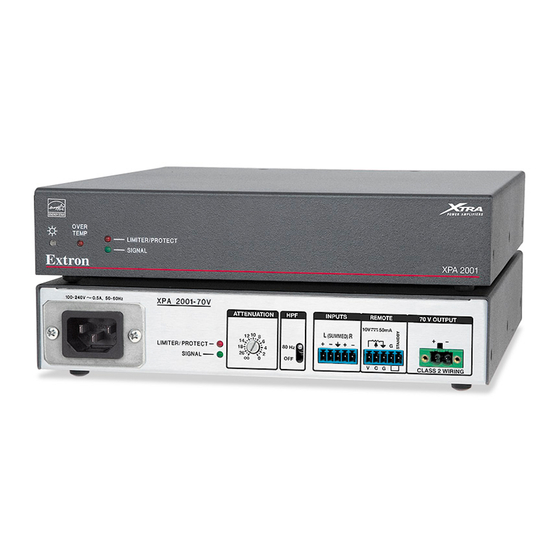
- Page 1 User Guide Power Amplifiers XTRA Series ™ XPA 1002, XPA 1002 Plus XPA 1002-70V, XPA 1002-100V XPA 2001-70V, XPA 2001-100V Half-Rack Audio Power Amplifiers 68-2354-01 Rev. C 07 20...
- Page 2 Safety Instructions Safety Instructions • English WARNING: This symbol, , when used on the product, is intended to alert the user of the presence of uninsulated dangerous voltage within the product’s enclosure that may present a risk of electric shock. ATTENTION: This symbol, , when used on the product, is intended...
- Page 3 Copyright © 2014-2020 Extron Electronics. All rights reserved. www.extron.com Trademarks All trademarks mentioned in this guide are the properties of their respective owners. The following registered trademarks ( ® ), registered service marks ( ), and trademarks ( ) are the property of RGB Systems, Inc. or Extron Electronics...
- Page 4 FCC Class B Notice NOTE: This device complies with part 15 of the FCC rules. Operation is subject to the following two conditions: (1) This device may not cause harmful interference, and (2) This device must accept any interference received, including interference that may cause undesired operation.
- Page 5 Conventions Used in this Guide Notifications The following notifications are used in this guide: WARNING: Potential risk of severe injury or death. AVERTISSEMENT : Risque potentiel de blessure grave ou de mort. CAUTION: Risk of minor personal injury. ATTENTION : Risque de blessure mineure.
-
Page 7: Table Of Contents
Terms Used in this Manual ....... 1 Features .............. 1 Installation ..........3 Application Examples .......... 3 Mounting the XTRA Series Amplifiers ....5 Tabletop Use ........... 5 UL Guidelines for Rack Mounting ..... 5 Rack Mounting ..........5 Flexible Conduit Adapter Kit Installation ... 7 Operation.......... - Page 8 Technical Publications Standards and Styles • Contents viii...
-
Page 9: Introduction
Introduction About this Manual This manual contains information about the Extron XTRA Series of power amplifiers. • XPA 1002 two-channel stereo audio power amplifier • XPA 1002 Plus two-channel stereo audio power amplifier • XPA 1002-70V two-channel audio power amplifier •... - Page 10 Highly efficient Class D amplifier design — The XTRA Series of amplifiers generate • substantially less heat than conventional amplifier designs, making them ideal for installation in equipment racks and lecterns with very limited ventilation. They consume 10 watts when idle and less than 1 watt in standby mode.
-
Page 11: Installation
Installation This section discusses how to install the XTRA Series of audio power amplifiers. Topics that are covered, include: • Application Examples • Mounting the XTRA Series Amplifiers CAUTION: Installation and service must be performed by authorized personnel only. ATTENTION : L’installation et l’entretien doivent être effectués par le personnel... - Page 12 Extron Projector with DVI In SW8 DVI A Plus DVI Switcher W/ Audio PC with DVI Out Laptop with DVI Out PC with DVI Out Figure 3. XPA 2001 Series Application Example XTRA Series Half-Rack Audio Power Amplifiers • Installation...
-
Page 13: Mounting The Xtra Series Amplifiers
Using screws longer than 3/16" will damage the unit and void the warranty. • L’utilisation de vis plus longues que 3/16" endommagera l’unité et annulera la garantie. Insert the screws from the underside of the shelf, and securely fasten them into diagonally-opposite corners. XTRA Series Half-Rack Audio Power Amplifiers • Installation... - Page 14 V e n V e n p a c p a c V e n V e n p a c p a c Figure 5. Rack Mounting Ventilation XTRA Series Half-Rack Audio Power Amplifiers • Installation...
-
Page 15: Flexible Conduit Adapter Kit Installation
A UL-listed electrical distribution box is recommended for the termination of the conduit opposite the XPA (see the UL Requirements section on page 8). • Un boîtier de distribution électrique listé UL est recommandé pour la terminaison du conduit à l’opposé du XPA. XTRA Series Half-Rack Audio Power Amplifiers • Installation... - Page 16 Lift Cover Straight Up Remove (8) screws W IR ∞ ∞ -6 0H , 50 0. 5A R /P IT E S IG 0- 24 L IM Figure 6. Removing the Cover XTRA Series Half-Rack Audio Power Amplifiers • Installation...
- Page 17 Connect the ground wire, as shown above, to the grounding stud on the bottom of the enclosure using the nut that was removed in step 4. Replace the cover of the XPA by attaching the 8 screws that were removed in step 2. XTRA Series Half-Rack Audio Power Amplifiers • Installation...
-
Page 18: Operation
Operation This section discusses how to operate the XTRA Series of half-rack audio power amplifiers. Topics that are covered, include: • Front Panel Features and Operation • Rear Panel Features and Operation Troubleshooting • Front Panel Features and Operation Power LED... - Page 19 SIGNAL LEDs — These LEDs (representing their respective output channels) light green only when an input SIGNAL signal is detected on the corresponding channel. NOTE: These LEDs are also located on the rear panel. XTRA Series Half-Rack Audio Power Amplifiers • Operation...
-
Page 20: Rear Panel Features And Operation
NOTE: Control signal ground pins may be labeled as , , or “G”. Audio ground pins may be labeled as or . The wiring and function are the same, whichever way your product is labeled. XTRA Series Half-Rack Audio Power Amplifiers • Operation... - Page 21 NOTE: When setting volume control through a source device, ensure that the volume of the device is set to variable out. Consult the user manual of the device for detailed instructions on its calibration. XTRA Series Half-Rack Audio Power Amplifiers • Operation...
- Page 22 (SUMMED) NOTE: On the XPA 1002 and XPA 2001, the input receptacle (MONO) may be labeled one of two ways. The wiring and function are the same, whichever your product is labeled. XTRA Series Half-Rack Audio Power Amplifiers • Operation...
- Page 23 Use the included 2-pin, 3.5 mm captive screw connector to remotely ground the standby pin. The power indicator LED lights amber when the amplifier is in standby mode. XTRA Series Half-Rack Audio Power Amplifiers • Operation...
- Page 24 Do not tin the wires! Be sure to observe the correct polarity. Insert the wired connector into the amplifier output and secure the locking screws on either side. XTRA Series Half-Rack Audio Power Amplifiers • Operation...
- Page 25 Step 1: Strip and insert the speaker wires into the connector and tighten the captive crews. Be sure to observe the correct polarity. Do not tin the wires! Step 2: Insert the wired connector into the amplifier output and secure the locking screws on either side. XTRA Series Half-Rack Audio Power Amplifiers • Operation...
-
Page 26: Remote Volume Control
NOTE: All nominal levels are at ±10%. REMOTE 50mA Extron STP 22 Cable Black Ground 50 mA VOL/MUTE VOLUME MUTE STANDBY VCM 100 Figure 11. VCM 100 MAAP Connection to XPA Remote Connector Pinout Diagram XTRA Series Half-Rack Audio Power Amplifiers • Operation... -
Page 27: Controlling Multiple Amplifiers With One
Regulating Multiple Amplifiers with a Single Volume Controller NOTE: The 10 V pin of the volume controller connects to the first XPA Half-Rack unit only. There are no jumper wires linking it to subsequent amplifiers. XTRA Series Half-Rack Audio Power Amplifiers • Operation... -
Page 28: Bridged Mono Output (Xpa 1002, Xpa 1002 Plus)
NOTE: During bridged mono output, the + output from channel 1 becomes the positive terminal and the + output from channel 2 becomes the negative terminal. Figure 13. Bridging the Output of the XPA 1002 and XPA 1002 Plus XTRA Series Half-Rack Audio Power Amplifiers • Operation... -
Page 29: Troubleshooting
(see amplifier specifications for details). Increase the signal level of the source until the SIGNAL LED lights consistently. XTRA Series Half-Rack Audio Power Amplifiers • Operation... -
Page 30: Limiter/Protect Led Warning Indicators
• Avoid placing equipment on top of (see figure 5 on page 6). the amplifier. • Verify that the operating temperature is within the specified range. XTRA Series Half-Rack Audio Power Amplifiers • Operation... -
Page 31: Reference
Reference Regulatory Statement - Taiwan XTRA Series Half-Rack Audio Power Amplifiers • Operation... - Page 32 Extron Electronics makes no further warranties either expressed or implied with respect to the product and its quality, performance, merchantability, or fitness for any particular use. In no event will Extron Electronics be liable for direct, indirect, or consequential damages resulting from any defect in this product even if Extron Electronics has been advised of such damage.
Need help?
Do you have a question about the XTRA Series and is the answer not in the manual?
Questions and answers