Table of Contents
Advertisement
Quick Links
Advertisement
Table of Contents

Subscribe to Our Youtube Channel
Related Manuals for Powerware 9390


Summary of Contents for Powerware 9390
- Page 1 (40–80 kVA) INSTALLATION & OPERATION MANUAL www.powerware.com...
-
Page 2: Important Safety Instructions
Corporation. Modbus is a registered trademark of Modicon. IBM and AS/400 are registered trademarks of International Business Machines Corp. ECopyright 2004 Powerware Corporation, Raleigh, NC, USA. All rights reserved. No part of this document may be reproduced in any way without the express written approval of Powerware... -
Page 3: Table Of Contents
..........Powerware 9390 UPS (40–80 kVA) Installation and Operation Manual S 164201535 Rev C ®... - Page 4 ......... . Powerware 9390 UPS (40–80 kVA) Installation and Operation Manual S 164201535 Rev C ®...
- Page 5 ......10-7 Powerware 9390 UPS (40–80 kVA) Installation and Operation Manual S 164201535 Rev C ®...
- Page 6 ............14-3 Powerware 9390 UPS (40–80 kVA) Installation and Operation Manual S 164201535 Rev C ®...
- Page 7 ..............Powerware 9390 UPS (40–80 kVA) Installation and Operation Manual S 164201535 Rev C ®...
- Page 8 ........Figure 2-1. Powerware 9390 UPS (40–80 kVA) Cabinet as Shipped on Pallet .
- Page 9 ..........13-5 Powerware 9390 UPS (40–80 kVA) Installation and Operation Manual S 164201535 Rev C ®...
- Page 10 This page intentionally left blank. viii Powerware 9390 UPS (40–80 kVA) Installation and Operation Manual S 164201535 Rev C ®...
-
Page 11: Introduction
AC power to protect the customer’s load from all nine power failures. The Powerware 9390 UPS is available as a single module or a multiple module parallel system (see paragraph 1.1). -
Page 12: Basic System Configurations
The UPS system configuration can be enhanced by adding optional accessories such as a Remote Emergency Power-Off (REPO) control, Remote Monitor Panel (RMP), or X-Slott communication cards. Powerware 9390 UPS (40–80 kVA) Installation and Operation Manual S 164201535 Rev C ®... -
Page 13: Installation Information
Introduction 1.2 Using This Manual This manual describes how to install and operate the Powerware 9390 UPS (40–80 kVA) cabinet. Read and understand the procedures described in this manual to ensure trouble-free installation and operation. In particular, be thoroughly familiar with the REPO procedure (see page 10-7). -
Page 14: Conventions Used In This Manual
In this manual, the term UPS refers only to the UPS cabinet and its internal elements. The term UPS system refers to the entire power protection system – the UPS cabinet, the battery cabinet, and options or accessories installed. Powerware 9390 UPS (40–80 kVA) Installation and Operation Manual S 164201535 Rev C ®... -
Page 15: Safety Warnings
Keep surroundings uncluttered, clean, and free from excess moisture. Observe all DANGER, CAUTION, and WARNING notices affixed to the inside and outside of the equipment. Powerware 9390 UPS (40–80 kVA) Installation and Operation Manual S 164201535 Rev C ®... -
Page 16: For More Information
Introduction 1.5 For More Information Refer to the Powerware 9390 Integrated Battery Cabinet (Models IBC-S and IBC-L) Installation Manual (164201536) for the following additional information: Integrated Battery Cabinet (IBC) installation instructions, including site preparation, planning for installation, wiring, and safety information. -
Page 17: Section I - Installation
Section I Installation Powerware 9390 UPS (40–80 kVA) Installation and Operation Manual S 164201535 Rev C ®... - Page 18 This page intentionally left blank. Powerware 9390 UPS (40–80 kVA) Installation and Operation Manual S 164201535 Rev C ®...
-
Page 19: Ups Installation Plan And Unpacking
You must allow clearance in front of and above each cabinet for proper air circulation. Powerware 9390 UPS (40–80 kVA) Installation and Operation Manual S 164201535 Rev C ®... -
Page 20: Environmental Considerations
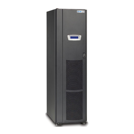
The next step is inspecting and unpacking the UPS cabinet. The cabinet is shipped bolted to a wooden pallet and protected with outer protective packaging material (see Figure 2-1). Powerware 9390 UPS (40–80 kVA) Installation and Operation Manual S 164201535 Rev C ®... -
Page 21: Figure 2-1. Powerware 9390 Ups (40-80 Kva) Cabinet As Shipped On Pallet
UPS Installation Plan and Unpacking Figure 2-1. Powerware 9390 UPS (40–80 kVA) Cabinet as Shipped on Pallet C A U T I O N The UPS cabinet is heavy (see Table A on page A-3). If unpacking instructions are not closely followed, the cabinet may tip and cause serious injury. - Page 22 While waiting for installation, protect the unpacked cabinet from moisture, dust, and other harmful contaminants. Failure to store and protect the UPS properly may void your warranty. Powerware 9390 UPS (40–80 kVA) Installation and Operation Manual S 164201535 Rev C ®...
-
Page 23: Installing The Ups System
Additional battery cabinets are supplied without cosmetic covers. Cosmetic covers must be ordered for the UPS cabinet and/or other ancillary cabinets. Powerware 9390 UPS (40–80 kVA) Installation and Operation Manual S 164201535 Rev C ®... -
Page 24: Unloading The Powerware 9390 Ups Cabinet From The Pallet
Do not discard the front anti-tip/shipping bracket. This bracket is required for installation. 7. Remove three bolts securing the removable skid and remove the skid (see Figure 3-2 on page 3-4). Powerware 9390 UPS (40–80 kVA) Installation and Operation Manual S 164201535 Rev C ®... -
Page 25: Figure 3-1. Removing Front Shipping Bracket On The Powerware 9390 Ups
Vented Front Door Shipping Bracket Bolts Pallet Shipping Bracket Bolts Front Anti-tip/Shipping Bracket (Note Wider Base) Figure 3-1. Removing Front Shipping Bracket on the Powerware 9390 UPS Powerware 9390 UPS (40–80 kVA) Installation and Operation Manual S 164201535 Rev C ®... -
Page 26: Figure 3-2. Removing Rear Shipping Bracket On The Powerware 9390 Ups
Skid Bolts (3 Places) Removable Skid Shipping Bracket Bolts Pallet Shipping Bracket Bolts Rear Shipping Bracket Figure 3-2. Removing Rear Shipping Bracket on the Powerware 9390 UPS Powerware 9390 UPS (40–80 kVA) Installation and Operation Manual S 164201535 Rev C ®... -
Page 27: Battery Cabinet Installation
3.2.3; otherwise, proceed to paragraph 3.2.4. 3.2.2 Battery Cabinet Installation To install the battery cabinet, refer to the Powerware 9390 Integrated Battery Cabinet (Models IBC-S and IBC-L) Installation Manual. After the battery cabinet is installed, return to paragraph 3.2.4 to wire the UPS and battery cabinet. -
Page 28: Integrated Distribution Cabinet Installation
Installing the UPS System 3.2.3 Integrated Distribution Cabinet Installation To install an IDC, refer to the Powerware 9390 Integrated Distribution Cabinet (80 kVA) Installation and Operation Manual. After the distribution cabinet is installed, return to paragraph 3.2.4 to wire the UPS and distribution cabinet. - Page 29 22. Connect the positive, negative, and ground DC power wiring from the battery cabinet to the UPS cabinet battery terminal block and ground terminals. See Appendix A for wiring and termination requirements. Powerware 9390 UPS (40–80 kVA) Installation and Operation Manual S 164201535 Rev C ®...
-
Page 30: Installing Interface Connections
Step 8. 7. Remove the screws securing the bottom internal safety shield panel and remove the panel to gain access to the bottom conduit landing plate. Powerware 9390 UPS (40–80 kVA) Installation and Operation Manual S 164201535 Rev C ®... -
Page 31: Tb2 Battery Cabinet Connections
7. If battery cabinets are installed attached to the UPS cabinet, proceed to Step 8; if battery cabinets are installed separated from the UPS cabinet, proceed to Step 11. Powerware 9390 UPS (40–80 kVA) Installation and Operation Manual S 164201535 Rev C ®... - Page 32 8. Route the UV trip and Aux wiring harness supplied with the battery cabinet from the battery cabinet to the UPS cabinet. Refer to Appendix A and to the Powerware 9390 Integrated Battery Cabinet (Models IBC-S and IBC-L) Installation Manual for wiring access information.
-
Page 33: X-Slot Connections
UPS cabinet. When installing internal wiring to X-Slot terminals, route the wiring through the internal opening in the X-Slot communication bay. For installation and setup of an X-Slot card, please contact Powerware (see page 1-6). To install wiring for connections: 1. -
Page 34: Completing The Installation Checklist
Installation Checklist to verify all applicable equipment installations have been completed. NOTE The Installation Checklist MUST be completed prior to starting the UPS system for the first time. 3-12 Powerware 9390 UPS (40–80 kVA) Installation and Operation Manual S 164201535 Rev C ®... -
Page 35: Installation Checklist
- Accessories are mounted in installed locations and wiring is terminated inside the UPS cabinet. (OPTIONAL) - Debris shield covering the UPS cabinet ventilation grill is removed. - Startup and operational checks are performed by an authorized Powerware Customer Service Engineer. 3-13 Powerware 9390 UPS (40–80 kVA) Installation and Operation Manual S 164201535 Rev C... - Page 36 - Backup control (pull chain) wiring between the UPMs is properly installed. - Adequate workspace exists around the UPMs, parallel tie cabinet, and other cabinets. - Startup and operational checks are performed by an authorized Powerware Customer Service Engineer. 3-14 Powerware 9390 UPS (40–80 kVA) Installation and Operation Manual S 164201535 Rev C...
- Page 37 Installing the UPS System Notes _________________________________________________________________________ _________________________________________________________________________ _________________________________________________________________________ _________________________________________________________________________ _________________________________________________________________________ _________________________________________________________________________ _________________________________________________________________________ _________________________________________________________________________ _________________________________________________________________________ _________________________________________________________________________ _________________________________________________________________________ _________________________________________________________________________ _________________________________________________________________________ _________________________________________________________________________ _________________________________________________________________________ _________________________________________________________________________ 3-15 Powerware 9390 UPS (40–80 kVA) Installation and Operation Manual S 164201535 Rev C ®...
- Page 38 Installing the UPS System This page intentionally left blank. 3-16 Powerware 9390 UPS (40–80 kVA) Installation and Operation Manual S 164201535 Rev C ®...
-
Page 39: Batteries
Proper disposal of batteries is required. Refer to your local codes for disposal requirements. Never dispose of batteries in a fire. Batteries may explode when exposed to flame. Powerware 9390 UPS (40–80 kVA) Installation and Operation Manual S 164201535 Rev C ®... -
Page 40: Installing Batteries
Do not discard the UPS or the UPS batteries in the trash. This product contains sealed, lead-acid batteries and must be disposed of properly. For more information, contact your local recycling or hazardous waste center. Powerware 9390 UPS (40–80 kVA) Installation and Operation Manual S 164201535 Rev C ®... -
Page 41: Figure 5-1. Repo Control
Retain the hardware for later use. 5. Remove the screws securing the control panel door and swing the door open. Retain the hardware for later use. Powerware 9390 UPS (40–80 kVA) Installation and Operation Manual S 164201535 Rev C ®... - Page 42 REPO switch rating is 24 Vdc. 1A minimum if supplied by user. NOTE This switch must be a dedicated switch not tied into any other circuits. Powerware 9390 UPS (40–80 kVA) Installation and Operation Manual S 164201535 Rev C ®...
- Page 43 16. Close the control panel door and secure with the retained hardware. 17. Reinstall the door removed in Step 4 and secure with the retained hardware. 18. Close the door and secure the latch. Powerware 9390 UPS (40–80 kVA) Installation and Operation Manual S 164201535 Rev C ®...
- Page 44 Installing a Remote Emergency Power-Off Control This page intentionally left blank. Powerware 9390 UPS (40–80 kVA) Installation and Operation Manual S 164201535 Rev C ®...
-
Page 45: Installing Options And Accessories
Remove the X-Slot cover panel to gain access to the X-Slot. See Drawing 164201535-8 starting on page A-33 for location of the X-Slot communication bay. 4. Proceed to paragraph 6.2. Powerware 9390 UPS (40–80 kVA) Installation and Operation Manual S 164201535 Rev C ®... -
Page 46: Preliminary Wiring Procedure
6. Install wiring from the Hot Sync CAN Bridge Card in accordance with the instructions listed below: Parallel system wiring (see paragraph 6.3) RMP wiring (see paragraph 6.4) RIM (see paragraph 6.5) SCM (see paragraph 6.6) Powerware 9390 UPS (40–80 kVA) Installation and Operation Manual S 164201535 Rev C ®... -
Page 47: Installing Parallel System Control Wiring
9. Close the control panel door and secure with the retained hardware. 10. Reinstall the door removed previously and secure with the retained hardware. 11. Close the door and secure the latch. Powerware 9390 UPS (40–80 kVA) Installation and Operation Manual S 164201535 Rev C ®... -
Page 48: Installing A Remote Monitor Panel
8. Install 120 Vac power wiring from the critical bus to the RMP. See Drawing 164201535-8 starting on page A-33 for terminal location and wiring information. Powerware 9390 UPS (40–80 kVA) Installation and Operation Manual S 164201535 Rev C ®... -
Page 49: Installing A Relay Interface Module
4. Remove the X-Slot conduit landing plate from the UPS cabinet to drill or punch conduit holes (see Drawing 164201535-6 on page A-27). 5. Reinstall the conduit landing plate. Powerware 9390 UPS (40–80 kVA) Installation and Operation Manual S 164201535 Rev C ®... - Page 50 Contacts are closed when approximately two minutes of battery time is remaining, before the critical load is lost. UTILITY FAILURE Pins 6 and 15 Contacts are closed when Utility Failure is detected. Powerware 9390 UPS (40–80 kVA) Installation and Operation Manual S 164201535 Rev C ®...
-
Page 51: Installing A Supervisory Contact Module
164201535-8 starting on page A-33 for terminal location and wiring information. NOTE Setup of the Hot Sync CAN Bridge Card must be performed by an authorized Powerware Customer Service Engineer. Contact service to schedule a date. Powerware 9390 UPS (40–80 kVA) Installation and Operation Manual S 164201535 Rev C ®... -
Page 52: Figure 6-2. Supervisory Contact Module Tb2
Supervisory contacts are rated at 2.0A at 28 Vdc or 120 Vac and 0.15A at 115 Vdc. Supervisory contacts require an external power supply. Internal 24 Vdc is not NOTE capable of supplying contact current. Powerware 9390 UPS (40–80 kVA) Installation and Operation Manual S 164201535 Rev C ®... -
Page 53: Section Ii Operation
Section II Operation Powerware 9390 UPS (40–80 kVA) Installation and Operation Manual S 164201535 Rev C ®... -
Page 54: Powerware ® 9390 Ups (40-80 Kva) Installation And Operation Manual S 164201535 Rev C
This page intentionally left blank. 6-10 Powerware 9390 UPS (40–80 kVA) Installation and Operation Manual S 164201535 Rev C ®... -
Page 55: Understanding Ups Operation
Understanding UPS Operation 7.1 Looking Inside the UPS System The Powerware 9390 UPS is a continuous-duty, solid-state, transformerless (at 208 and 480 Vac), three-phase, true online system that provide conditioned and uninterruptible AC power to the UPS systems output. The UPS supports process control, data processing, telecommunications/PBX, research, and non-patient medical equipment. -
Page 56: Single Module Reverse Transfer (Rt)
7.2.1 Single Module RT Modes The Powerware 9390 UPS supports a critical load in three different modes of operation. The UPS can automatically use all three modes, as required. The standard operation... - Page 57 System Events.” The following paragraphs describe the differences in the three UPS operating modes, using block diagrams to show the power flow during each mode of operation. Powerware 9390 UPS (40–80 kVA) Installation and Operation Manual S 164201535 Rev C ®...
-
Page 58: Figure 7-2. Path Of Current Through The Ups In Normal Mode - Rt
The UPS monitors the battery charge condition and reports the status on the control panel. The battery is always connected to the UPS and ready to support the inverter should the utility input become unavailable. Powerware 9390 UPS (40–80 kVA) Installation and Operation Manual S 164201535 Rev C ®... - Page 59 If the UPS suffers an internal failure, it switches automatically to Bypass mode and remains in that mode until the failure is corrected and the UPS is back in service. Powerware 9390 UPS (40–80 kVA) Installation and Operation Manual S 164201535 Rev C ®...
-
Page 60: Figure 7-3. Path Of Current Through The Ups In Bypass Mode - Rt
K3 opens to isolates the inverter. The backfeed protection contactor is normally always closed, ready to support the static switch unless the bypass input source becomes unavailable. Powerware 9390 UPS (40–80 kVA) Installation and Operation Manual S 164201535 Rev C ®... - Page 61 Bypass mode is a normal operating mode, not an alarm condition. However, if the UPS is unable to return to Normal mode following an automatic transfer to Bypass mode, an alarm condition is recorded. Powerware 9390 UPS (40–80 kVA) Installation and Operation Manual S 164201535 Rev C ®...
-
Page 62: Figure 7-4. Path Of Current Through The Ups In Battery Mode - Rt
The UPS remains in this operating mode until the input power to the rectifier is again within the specified voltage or frequency acceptance windows. Powerware 9390 UPS (40–80 kVA) Installation and Operation Manual S 164201535 Rev C ®... -
Page 63: Multiple Module Parallel System
7.3 Multiple Module Parallel System Parallel operation extends the normal operation of Powerware 9390 UPS units by offering increased capacity and/or redundant capability. The parallel system continues to maintain power to the critical loads during commercial electrical power brownout, blackout, overvoltage, undervoltage, and out-of-tolerance frequency conditions. -
Page 64: Multiple Module Parallel System Modes
UPMs online than required to support the load. 7.3.1 Multiple Module Parallel System Modes Similar to the single module system, the Powerware 9390 UPS parallel system supports a critical load in three different modes of operation. The standard operation modes are: In Normal mode, the paralleled UPMs supply the critical load with clean, filtered power. -
Page 65: Figure 7-5. Path Of Current Through The Upms In Normal Mode - Parallel
If the UPMs become overloaded or unavailable, the parallel system switches to Bypass mode. The parallel system automatically returns to Normal mode when the overload condition is cleared and system operation is restored within specified limits. 7-11 Powerware 9390 UPS (40–80 kVA) Installation and Operation Manual S 164201535 Rev C ®... -
Page 66: Figure 7-6. Path Of Current Through The Upms In Bypass Mode - Parallel
If the more modules than can support the load must be taken offline, the load must be transferred to maintenance bypass or shut down. 7-12 Powerware 9390 UPS (40–80 kVA) Installation and Operation Manual S 164201535 Rev C ®... - Page 67 In the Parallel Capacity (N + 0) arrangement, if one unit trips offline and goes to BYPASS, the remaining units also go to BYPASS. 7-13 Powerware 9390 UPS (40–80 kVA) Installation and Operation Manual S 164201535 Rev C ®...
-
Page 68: Figure 7-7. Path Of Current Through The Upms In Battery Mode - Parallel
The UPMs remains in this operating mode until the input power to the rectifier is again within the specified voltage or frequency acceptance windows. 7-14 Powerware 9390 UPS (40–80 kVA) Installation and Operation Manual S 164201535 Rev C ®... -
Page 69: Functional Description
ABM extends battery life by keeping the batteries charged and performing periodic battery testing. 7-15 Powerware 9390 UPS (40–80 kVA) Installation and Operation Manual S 164201535 Rev C ®... -
Page 70: Bypass
A backfeed contactor is also provided. 7.4.5 Batteries The UPS operates from battery strings from 192 cells (384V nominal) to 240 cells (480V nominal). 7-16 Powerware 9390 UPS (40–80 kVA) Installation and Operation Manual S 164201535 Rev C ®... -
Page 71: Features, Options, And Accessories
A ConnectUPS -X Web/SNMP Card is provided as standard equipment and provides remote monitoring through a Web browser interface, e-mail, and a network management system (NMS) using SNMP. See Chapter 13, “Communication,” for additional information. Powerware 9390 UPS (40–80 kVA) Installation and Operation Manual S 164201535 Rev C ®... -
Page 72: Advanced Battery Management
Charging at high currents can overheat and damage batteries. 8.1.6 LanSafe Power Management Software LanSafe Power Management Software is bundled as part of the Powerware Software Suite CD shipped with the UPS. See Chapter 13, “Communication,” for additional information. -
Page 73: Hotsync Parallel System
An optional SCM establishes an interface between the UPS system equipment and the customer’s monitor. This option is described further in Chapter 11, “Using Features and Options.” Powerware 9390 UPS (40–80 kVA) Installation and Operation Manual S 164201535 Rev C ®... -
Page 74: Symbols, Controls, And Indicators
This symbol indicates that you should not discard the UPS or the UPS batteries in the trash. The UPS may contain sealed, lead-acid batteries. Batteries must be recycled. Powerware 9390 UPS (40–80 kVA) Installation and Operation Manual S 164201535 Rev C ®... -
Page 75: Using The Control Panel
Chapter 10, “UPS Operating Instructions,” for use of the operational controls. When the unit powers up, the screen displays the Powerware logo as shown in Figure 9-1. To advance to the Main Menu and Mimic screen, press any control panel pushbutton once. -
Page 76: Using The Lcd And Pushbuttons
LOAD OFF Figure 9-2. Parts of the LCD A The UPS status area automatically scrolls between the Powerware model number, current date and time, active alarms, active notices, and load percent and battery run time for the UPS. Shown is a typical alarm message. (For more information about alarms and notices, see Chapter 12, “Responding to System Events.”) -
Page 77: Using The Main Menu
DATE: 02 / 25 / 2004 INPUT BATT STSW OUTPUT BYPASS EVENTS METERS CONTROLS SETUP LOAD OFF Figure 9-3. Main Menu and Mimic Screen (Normal Mode) Powerware 9390 UPS (40–80 kVA) Installation and Operation Manual S 164201535 Rev C ®... -
Page 78: Event Screens
ALARM: BYPASS AC UNDER VOLTAGE NOTICE: BATTERY VOLTAGE LOW NOTICE: NO SYNC ON NOTICE: BYPASS NOT AVAILABLE NOTICE: CONFIGURATION ERROR HISTORY Figure 9-4. Active Events Screen Powerware 9390 UPS (40–80 kVA) Installation and Operation Manual S 164201535 Rev C ®... -
Page 79: Figure 9-5. History Screen
TO BYPASS COMMAND UPS OFF NOTICE: 5 of 29 02 / 26 / 2004 10 : 20 : 03 . 539 EVENTS Figure 9-5. History Screen Powerware 9390 UPS (40–80 kVA) Installation and Operation Manual S 164201535 Rev C ®... -
Page 80: Unit Meter Screens
UPS, as well as the kVA, kW, and power factor measurements. OUTPUT --- UNIT FREQ LEAD SYSTEM UNIT Figure 9-6. Unit Output Meter Screen Powerware 9390 UPS (40–80 kVA) Installation and Operation Manual S 164201535 Rev C ®... -
Page 81: Figure 9-7. Unit Input Meter Screen
BYPASS --- UNIT FREQ LEAD SYSTEM UNIT Figure 9-8. Unit Bypass Meter Screen Powerware 9390 UPS (40–80 kVA) Installation and Operation Manual S 164201535 Rev C ®... -
Page 82: Figure 9-9. Unit Battery Meter Screen
The Output Current Screen displays a real-time bar graph of the output current of the UPS. The graph shows the current for each phase. OUTPUT CURRENT --- UNIT 125% 100% SYSTEM UNIT Figure 9-10. Unit Output Current (Load) Meter Screen Powerware 9390 UPS (40–80 kVA) Installation and Operation Manual S 164201535 Rev C ®... -
Page 83: System Meters Screens
SELECT pushbutton to display the screen. SYSTEM METERS TOTAL SYSTEM UNIT 1 UNIT 2 ENTER PASS- UNIT 3 WORD UNIT 4 SELECT Figure 9-11. System Meters Screen Powerware 9390 UPS (40–80 kVA) Installation and Operation Manual S 164201535 Rev C ®... -
Page 84: Figure 9-12. Total System Output Meter Screen
PF is calculated from the total values for the kVA and kW. OUTPUT TOTAL SYSTEM FREQ LEAD SYSTEM UNIT Figure 9-12. Total System Output Meter Screen 9-10 Powerware 9390 UPS (40–80 kVA) Installation and Operation Manual S 164201535 Rev C ®... -
Page 85: Figure 9-13. Output Unit X Meter Screen
UPS, as well as the kVA, kW, and power factor measurements for the selected unit. OUTPUT UNIT X FREQ LEAD SYSTEM UNIT Figure 9-13. Output Unit X Meter Screen 9-11 Powerware 9390 UPS (40–80 kVA) Installation and Operation Manual S 164201535 Rev C ®... -
Page 86: Figure 9-14. Input Unit X Meter Screen
BYPASS UNIT X FREQ LEAD SYSTEM UNIT Figure 9-15. Bypass Unit X Meter Screen 9-12 Powerware 9390 UPS (40–80 kVA) Installation and Operation Manual S 164201535 Rev C ®... -
Page 87: Figure 9-16. Battery Unit X Meter Screen
The graph shows the current for each phase. OUTPUT CURRENT UNIT X 125% 100% SYSTEM UNIT Figure 9-17. Output Current (Load) Unit X Meter Screen 9-13 Powerware 9390 UPS (40–80 kVA) Installation and Operation Manual S 164201535 Rev C ®... -
Page 88: System Setup Level 0 Screens
SELECT pushbutton to display the function screen. SYSTEM SETUP LEVEL 0 ENTER PASSWORD CONTRAST ADJUST VERSIONS UNIT TYPE SELECT Figure 9-18. System Setup Level 0 Screen 9-14 Powerware 9390 UPS (40–80 kVA) Installation and Operation Manual S 164201535 Rev C ®... -
Page 89: Figure 9-19. Contrast Adjust Screen
Setup screen displays. To return to the System Setup screen without saving the setting, press the pushbutton. CONTRAST ADJUST SAVE Figure 9-19. Contrast Adjust Screen 9-15 Powerware 9390 UPS (40–80 kVA) Installation and Operation Manual S 164201535 Rev C ®... -
Page 90: Figure 9-20. Versions Screen
Figure 9-21 shows the Unit Type screen. To return to the System Setup screen, press the pushbutton. UNIT TYPE MODEL: POWERWARE 9390 CTO: 0000000000000000 SERIAL: 0000000000000000 Figure 9-21. Unit Type Screen 9-16 Powerware 9390 UPS (40–80 kVA) Installation and Operation Manual S 164201535 Rev C ®... -
Page 91: System Setup Level 1 Screens
Once the password is entered, press the DONE pushbutton. The System Setup Level 1 menu screen is displayed. The default password is L1. ENTER PASSWORD DONE Figure 9-22. Enter Password Screen 9-17 Powerware 9390 UPS (40–80 kVA) Installation and Operation Manual S 164201535 Rev C ®... -
Page 92: Figure 9-23. System Setup Level 1 Screen
SYSTEM SETUP LEVEL 1 LOG OUT ENTER PASSWORD CHANGE PASSWORD ENTER PASS- CONTRAST ADJUST WORD VERSIONS UNIT TYPE SELECT Figure 9-23. System Setup Level 1 Screen 9-18 Powerware 9390 UPS (40–80 kVA) Installation and Operation Manual S 164201535 Rev C ®... -
Page 93: Figure 9-24. Change Password Screen
Once the new password is entered, press the DONE pushbutton. The Change Password Save screen is displayed. CHANGE PASSWORD OLD: NEW: DONE Figure 9-24. Change Password Screen 9-19 Powerware 9390 UPS (40–80 kVA) Installation and Operation Manual S 164201535 Rev C ®... -
Page 94: Figure 9-25. Change Password Save Screen
System Setup screen displays. If RETRY is pressed, the Change Password screen is redisplayed. CHANGE PASSWORD OLD: NEW: SAVE RETRY ABORT Figure 9-25. Change Password Save Screen 9-20 Powerware 9390 UPS (40–80 kVA) Installation and Operation Manual S 164201535 Rev C ®... -
Page 95: Figure 9-26. Time Format Screen
Set Date and Time screen. To return to the System Setup screen, press the pushbutton. TIME FORMAT SETUP MM/DD/YYYY DD/MM/YYYY SELECT Figure 9-26. Time Format Screen 9-21 Powerware 9390 UPS (40–80 kVA) Installation and Operation Manual S 164201535 Rev C ®... -
Page 96: Figure 9-27. Set Date And Time Mm/Dd/Yyyy Screen
System Setup screen, select the pushbutton. SET DATE AND TIME MM/DD/YYYY MONTH DATE YEAR HOUR MINUTE SAVE 2004 Figure 9-27. Set Date and Time MM/DD/YYYY Screen 9-22 Powerware 9390 UPS (40–80 kVA) Installation and Operation Manual S 164201535 Rev C ®... -
Page 97: Figure 9-28. Date And Time Dd/Mm/Yyyy Screen
System Setup screen, select the pushbutton. SET DATE AND TIME DD/MM/YYYY DATE MONTH YEAR HOUR MINUTE SAVE 2004 Figure 9-28. Date and Time DD/MM/YYYY Screen 9-23 Powerware 9390 UPS (40–80 kVA) Installation and Operation Manual S 164201535 Rev C ®... -
Page 98: Figure 9-29. Com Port Setup Screen
SELECT pushbutton. To return to the System Setup screen, press the pushbutton. COM PORT SETUP COM 1 COM 2 COM 3 SELECT Figure 9-29. COM Port Setup Screen 9-24 Powerware 9390 UPS (40–80 kVA) Installation and Operation Manual S 164201535 Rev C ®... -
Page 99: Figure 9-30. Com Setup Screen
Once the action is completed, the COM Port Setup screen appears. COM 1 SETUP BAUD RATE 19200 DATA BITS STOP BITS PARITY NONE ABORT SAVE Figure 9-30. COM Setup Screen 9-25 Powerware 9390 UPS (40–80 kVA) Installation and Operation Manual S 164201535 Rev C ®... -
Page 100: Figure 9-31. System Controls Screen 1
System Controls screens. SYSTEM CONTROLS MAINTENANCE BYPASS BYPASS ONLINE POWER MODULE (PM) CHARGER LOAD OFF NORMAL BYPASS Figure 9-31. System Controls Screen 1 9-26 Powerware 9390 UPS (40–80 kVA) Installation and Operation Manual S 164201535 Rev C ®... -
Page 101: Figure 9-32. System Controls Screen 2
The CHGR pushbutton switch toggles the charger function On and Off. The PM pushbutton switch toggles the power module function On and Off. For detailed information about using the System Controls, see Chapter 10, “UPS Operating Instructions.” 9-27 Powerware 9390 UPS (40–80 kVA) Installation and Operation Manual S 164201535 Rev C ®... -
Page 102: Figure 9-33. Load Off Screen
Off screen. For detailed information about using the LOAD OFF and Shutdown screens, see Chapter 10, “UPS Operating Instructions.” HOLD LOAD OFF BUTTON FOR 3 SECONDS TO TURN OFF LOAD CANCEL LOAD OFF Figure 9-33. Load Off Screen 9-28 Powerware 9390 UPS (40–80 kVA) Installation and Operation Manual S 164201535 Rev C ®... -
Page 103: Reading The Status Indicators
The indicator flashes until acknowledged by pressing any control panel pushbutton once. For more information about audible horns, see “System Event Horns” on page 12-1. 9-29 Powerware 9390 UPS (40–80 kVA) Installation and Operation Manual S 164201535 Rev C ®... - Page 104 Using the Control Panel This page intentionally left blank. 9-30 Powerware 9390 UPS (40–80 kVA) Installation and Operation Manual S 164201535 Rev C ®...
-
Page 105: Ups Operating Instructions
Normal mode. The status indicator on the UPS control panel indicates the UPS is in Bypass mode. If Auto Bypass is not enabled, the UPS output remains off until the UPS transfers to Normal mode. 10-1 Powerware 9390 UPS (40–80 kVA) Installation and Operation Manual S 164201535 Rev C ®... -
Page 106: Starting The Ups In Bypass Mode
The critical load is immediately supplied by the bypass source, in Bypass mode. 7. The UPS is now operating in Bypass mode and the BYPASS status indicator is illuminated. 10-2 Powerware 9390 UPS (40–80 kVA) Installation and Operation Manual S 164201535 Rev C ®... -
Page 107: Starting The Power Module
The UPS transfers to Bypass mode and the critical load is immediately supplied by the bypass source. If the bypass source is not available, the power processor remains on and an alarm sounds. 10-3 Powerware 9390 UPS (40–80 kVA) Installation and Operation Manual S 164201535 Rev C ®... -
Page 108: Transfer From Bypass To Normal Mode
The bypass source supplies the critical load. W A R N I N G Power is present inside the UPS cabinets. 10-4 Powerware 9390 UPS (40–80 kVA) Installation and Operation Manual S 164201535 Rev C ®... -
Page 109: Ups And Critical Load Shutdown
System Controls Screen 2. 3. Press the CHGR ON or CHGR OFF pushbutton on the System Controls menu bar to toggle the charger on or off. 10-5 Powerware 9390 UPS (40–80 kVA) Installation and Operation Manual S 164201535 Rev C ®... -
Page 110: Using The Ups Load Off Pushbutton
Do not attempt to restart the system after Load Off until the cause of the shutdown has been identified and cleared. 3. To restart the UPS after pressing the LOAD OFF pushbutton, follow the procedure in paragraph 10.1.1 or 10.1.2. 10-6 Powerware 9390 UPS (40–80 kVA) Installation and Operation Manual S 164201535 Rev C ®... -
Page 111: Using The Remote Emergency Power-Off Switch
2. To restart the UPS after using the REPO pushbutton, reset the REPO switch and then follow the procedure in paragraph 10.1.1 or 10.1.2. 10-7 Powerware 9390 UPS (40–80 kVA) Installation and Operation Manual S 164201535 Rev C ®... -
Page 112: Multiple Module Parallel Operation
CLOSE BATTERY appears on the display. 9. The UPMs are now operating in Normal mode and the NORMAL status indicator on each UPM is illuminated. 10-8 Powerware 9390 UPS (40–80 kVA) Installation and Operation Manual S 164201535 Rev C ®... -
Page 113: Starting The Parallel System In Bypass Mode
The critical load is immediately supplied by the bypass source, in Bypass mode. 7. The UPMs are now operating in Bypass mode and the BYPASS status indicator on each UPM is illuminated. 10-9 Powerware 9390 UPS (40–80 kVA) Installation and Operation Manual S 164201535 Rev C ®... -
Page 114: Transfer Parallel System From Normal To Bypass Mode
3. The UPMs are now operating in Normal mode, and the NORMAL status indicator on each UPM is illuminated. The power module (PM) status indicates ONLINE on each UPM. 10-10 Powerware 9390 UPS (40–80 kVA) Installation and Operation Manual S 164201535 Rev C ®... -
Page 115: Single Upm Shutdown
5. Press the CONTROLS pushbutton on the main menu bar of the UPM. The System Controls screen appears. 6. On the System Controls screen, the power module (PM) status should indicate SHUTDOWN. 10-11 Powerware 9390 UPS (40–80 kVA) Installation and Operation Manual S 164201535 Rev C ®... -
Page 116: Parallel System And Critical Load Shutdown
REPO pushbutton switch. See “Using the Parallel System Remote Emergency Power-Off Switch” in paragraph 10.2.9. 7. To shut down the last UPM, press the REPO pushbutton switch. 10-12 Powerware 9390 UPS (40–80 kVA) Installation and Operation Manual S 164201535 Rev C ®... -
Page 117: Using The Ups Load Off Pushbutton
Do not attempt to restart the system after Load Off until the cause of the shutdown has been identified and cleared. 3. To restart the UPS after pressing the LOAD OFF pushbutton, follow the procedure, in paragraphs 10.2.1 or 10.2.2. 10-13 Powerware 9390 UPS (40–80 kVA) Installation and Operation Manual S 164201535 Rev C ®... -
Page 118: Using The Parallel System Remote Emergency Power-Off Switch
2. To restart the UPMs after using the REPO pushbutton, reset the REPO switch and then follow the procedure in paragraph 10.2.1 or 10.2.2. 10-14 Powerware 9390 UPS (40–80 kVA) Installation and Operation Manual S 164201535 Rev C ®... -
Page 119: Using Features And Options
UPS horn may not be heard immediately. C A U T I O N Contacts should not be operated in excess of 120 Vac @ 5A maximum. 11-1 Powerware 9390 UPS (40–80 kVA) Installation and Operation Manual S 164201535 Rev C ®... -
Page 120: Optional Remote Monitor Panel
(see Table 11-1). Figure 11-1 shows an RMP. Figure 11-1. Remote Monitor Panel Table 11-1. Optional Monitoring Accessories Number and Type of Accessories Permitted — — — — — — 11-2 Powerware 9390 UPS (40–80 kVA) Installation and Operation Manual S 164201535 Rev C ®... - Page 121 The UPS is preparing to shut down because the UPS is in Battery mode and the DC voltage is approaching its low limit. This indicator is accompanied by a horn. 11-3 Powerware 9390 UPS (40–80 kVA) Installation and Operation Manual S 164201535 Rev C ®...
-
Page 122: Figure 11-2. Relay Interface Module
Contacts are closed when approximately two minutes of battery time is remaining, before the critical load is lost. UTILITY FAILURE Pins 6 and 15 Contacts are closed when Utility Failure is detected. 11-4 Powerware 9390 UPS (40–80 kVA) Installation and Operation Manual S 164201535 Rev C ®... -
Page 123: Figure 11-3. Supervisory Contact Module
BYPASS NOT AVAILABLE TB2-10 through TB2-12 ON BATTERY TB2-13 through TB2-15 UPS ALARM TB2-16 through TB2-18 ON BYPASS TB2-19 through TB2-21 SHUTDOWN IMMINENT TB2-22 through TB2-24 11-5 Powerware 9390 UPS (40–80 kVA) Installation and Operation Manual S 164201535 Rev C ®... - Page 124 Using Features and Options This page intentionally left blank. 11-6 Powerware 9390 UPS (40–80 kVA) Installation and Operation Manual S 164201535 Rev C ®...
-
Page 125: Responding To System Events
The messages are divided into four categories: alarms, notices, status, and commands. The following tables contain the events displayed on the Events screen of the control panel. 12-1 Powerware 9390 UPS (40–80 kVA) Installation and Operation Manual S 164201535 Rev C ®... - Page 126 *Log codes indicate where the UPS records the event: H = History log; HA = History and Active logs; and A = Active log only. 12-2 Powerware 9390 UPS (40–80 kVA) Installation and Operation Manual S 164201535 Rev C ®...
- Page 127 *Log codes indicate where the UPS records the event: H = History log; HA = History and Active logs; and A = Active log only. 12-3 Powerware 9390 UPS (40–80 kVA) Installation and Operation Manual S 164201535 Rev C ®...
- Page 128 *Log codes indicate where the UPS records the event: H = History log; HA = History and Active logs; and A = Active log only. 12-4 Powerware 9390 UPS (40–80 kVA) Installation and Operation Manual S 164201535 Rev C ®...
- Page 129 *Log codes indicate where the UPS records the event: H = History log; HA = History and Active logs; and A = Active log only. 12-5 Powerware 9390 UPS (40–80 kVA) Installation and Operation Manual S 164201535 Rev C ®...
- Page 130 *Log codes indicate where the UPS records the event: H = History log; HA = History and Active logs; and A = Active log only. 12-6 Powerware 9390 UPS (40–80 kVA) Installation and Operation Manual S 164201535 Rev C ®...
- Page 131 *Log codes indicate where the UPS records the event: H = History log; HA = History and Active logs; and A = Active log only. 12-7 Powerware 9390 UPS (40–80 kVA) Installation and Operation Manual S 164201535 Rev C ®...
- Page 132 *Log codes indicate where the UPS records the event: H = History log; HA = History and Active logs; and A = Active log only. 12-8 Powerware 9390 UPS (40–80 kVA) Installation and Operation Manual S 164201535 Rev C ®...
- Page 133 *Log codes indicate where the UPS records the event: H = History log; HA = History and Active logs; and A = Active log only. 12-9 Powerware 9390 UPS (40–80 kVA) Installation and Operation Manual S 164201535 Rev C ®...
- Page 134 Responding to System Events This page intentionally left blank. 12-10 Powerware 9390 UPS (40–80 kVA) Installation and Operation Manual S 164201535 Rev C ®...
-
Page 135: Communication
LAN and telephone drops for use with X-Slot connectivity cards must be provided by facility planners or the customer. For installation and setup of an X-Slot card, please contact Powerware (see page 1-6). Refer to the manual supplied with the X-Slot card for user instructions. -
Page 136: Lansafe Power Management Software
Industrial Relay Card Figure 13-1. Optional X-Slot Cards 13.2 LanSafe Power Management Software Each Powerware 9390 UPS ships with LanSafe Power Management Software. To begin installing LanSafe software, see the instructions accompanying the Powerware Software Suite CD. LanSafe software uses an RS-232 serial link to communicate with the UPS. The software provides up-to-date graphics of UPS power and system data and power flow, a complete record of critical power events, and notification of important UPS or power information. -
Page 137: Terminal Mode
To remotely control the UPS or view UPS information, use the escape key legend to control the function normally controlled by the control panel softkeys. See Chapter 9, “Using the Control Panel,” for instructions on navigating the control panel. 13-3 Powerware 9390 UPS (40–80 kVA) Installation and Operation Manual S 164201535 Rev C ®... -
Page 138: Event History Log
If a port is operating in Terminal mode and is connected to a computer, you can press [Esc] [H] to print the entire log with a firmware version header. 13-4 Powerware 9390 UPS (40–80 kVA) Installation and Operation Manual S 164201535 Rev C ®... -
Page 139: Figure 13-2. Sample Event History Log
03/12/2004 14:17:25.557 ALARM: Battery Under Voltage OK 03/12/2004 14:19:01.899 CMD: PPU On Command 03/12/2004 14:19:04.089 STATUS: K1 (Input) Closed Figure 13-2. Sample Event History Log 13-5 Powerware 9390 UPS (40–80 kVA) Installation and Operation Manual S 164201535 Rev C ®... - Page 140 Communication This page intentionally left blank. 13-6 Powerware 9390 UPS (40–80 kVA) Installation and Operation Manual S 164201535 Rev C ®...
-
Page 141: Maintaining The Ups System
Wear rubber gloves and boots. Do not lay tools or metal parts on top of batteries or battery cabinets. Disconnect the charging source prior to connecting or disconnecting terminals. 14-1 Powerware 9390 UPS (40–80 kVA) Installation and Operation Manual S 164201535 Rev C ®... -
Page 142: Performing Preventive Maintenance
2. Ensure the air intakes (vents on the front doors) and exhaust opening (on top of the UPS cabinet sections) are not blocked. 14-2 Powerware 9390 UPS (40–80 kVA) Installation and Operation Manual S 164201535 Rev C ®... -
Page 143: Monthly Maintenance
For more information about training and other services, contact the Powerware Training Coordinator in Raleigh, North Carolina, or call your Powerware service representative (see page 1-6). 14-3 Powerware 9390 UPS (40–80 kVA) Installation and Operation Manual S 164201535 Rev C ®... - Page 144 Maintaining the UPS System This page intentionally left blank. 14-4 Powerware 9390 UPS (40–80 kVA) Installation and Operation Manual S 164201535 Rev C ®...
-
Page 145: Product Specifications
Line Surges 6 kV OC, 3 kA SC per ANSI 62.41 and IEC 801-4 Battery Voltage 384 Vdc (208V units only) 432 Vdc 480 Vdc 15-1 Powerware 9390 UPS (40–80 kVA) Installation and Operation Manual S 164201535 Rev C ®... -
Page 146: Ups System Output
Meets IEC 801-2 specifications. Withstands up to 25 kV pulse (ESD) Immunity without damage and with no disturbance or adverse effect to the critical load. 15-2 Powerware 9390 UPS (40–80 kVA) Installation and Operation Manual S 164201535 Rev C ®... -
Page 147: Multiple Module Parallel Specifications
208 Vac for operation from 177 Vac to 229 Vac (UPM Dependent) 480 Vac for operation from 408 Vac to 528 Vac Operating Output Current See Appendix A, Table P through Table S. 15-3 Powerware 9390 UPS (40–80 kVA) Installation and Operation Manual S 164201535 Rev C ®... - Page 148 Product Specifications This page intentionally left blank. 15-4 Powerware 9390 UPS (40–80 kVA) Installation and Operation Manual S 164201535 Rev C ®...
-
Page 149: Installation Information
164201535-9 UPS Cabinet Dimensions 164201535-10 Optional Remote Emergency Power-Off 164201535-11 Optional Remote Monitor Panel 164201535-12 Optional Remote Relay Interface Module 164201535-13 Optional Remote Supervisory Contact Module Powerware 9390 UPS (40–80 kVA) Installation and Operation Manual S 164201535 Rev C ®... -
Page 150: Battery Cabinet
Installation Information BATTERY CABINET UPS CABINET DESCRIPTION: TYPICAL POWERWARE 9390 UPS SYSTEM DRAWING NO: SHEET: 164201535---1 1 of 1 REVISION: DATE: 111504 Powerware 9390 UPS (40–80 kVA) Installation and Operation Manual S 164201535 Rev C ®... - Page 151 From Right Side of Cabinet None Required From Left Side of Cabinet None Required DESCRIPTION: PHYSICAL FEATURES AND REQUIREMENTS DRAWING NO: SHEET: 164201535---2 1 of 2 REVISION: DATE: 111504 Powerware 9390 UPS (40–80 kVA) Installation and Operation Manual S 164201535 Rev C ®...
- Page 152 Ventilation required for cooling air exhaust: approximately 4.72 liter/sec (1000 cfm). DESCRIPTION: PHYSICAL FEATURES AND REQUIREMENTS DRAWING NO: SHEET: 164201535---2 2 of 2 REVISION: DATE: 111504 Powerware 9390 UPS (40–80 kVA) Installation and Operation Manual S 164201535 Rev C ®...
- Page 153 Single or Dual Feed 9390---60 3+1 and 4+0 Configurations 480/480 9390---80 DESCRIPTION: UPS SYSTEM ONELINE CONFIGURATIONS DRAWING NO: SHEET: 164201535---3 1 of 1 REVISION: DATE: 111504 Powerware 9390 UPS (40–80 kVA) Installation and Operation Manual S 164201535 Rev C ®...
- Page 154 480V INPUT AND 480V OUTPUT SINGLE OR DUAL FEED DESCRIPTION: UPS SYSTEM ONELINE DRAWING NOTE: Remove jumper for dual feed. DRAWING NO: SHEET: 164201535---4 1 of 5 REVISION: DATE: 111504 Powerware 9390 UPS (40–80 kVA) Installation and Operation Manual S 164201535 Rev C ®...
- Page 155 TYPICAL MAINTENANCE BYPASS PANEL POWER FLOW MIB: MAINTENANCE ISOLATION BREAKER DESCRIPTION: UPS SYSTEM ONELINE DRAWING MBP: MAINTENANCE BYPASS BREAKER DRAWING NO: SHEET: 164201535---4 2 of 5 REVISION: DATE: 111504 Powerware 9390 UPS (40–80 kVA) Installation and Operation Manual S 164201535 Rev C ®...
- Page 156 UPS SYSTEM ONELINE DRAWING DRAWING NO: SHEET: 3 of 5 164201535---4 3. If the load requires a neutral, a bypass neutral feeder must be supplied. REVISION: DATE: 093004 Powerware 9390 UPS (40–80 kVA) Installation and Operation Manual S 164201535 Rev C ®...
- Page 157 UPS SYSTEM ONELINE DRAWING DRAWING NO: SHEET: 4 of 5 3. If the load requires a neutral, a bypass 164201535---4 neutral feeder must be supplied. REVISION: DATE: 093004 Powerware 9390 UPS (40–80 kVA) Installation and Operation Manual S 164201535 Rev C ®...
- Page 158 UPS SYSTEM ONELINE DRAWING DRAWING NO: SHEET: 5 of 5 3. If the load requires a neutral, a bypass 164201535---4 neutral feeder must be supplied. REVISION: DATE: 093004 A-10 Powerware 9390 UPS (40–80 kVA) Installation and Operation Manual S 164201535 Rev C ®...
- Page 159 Refer to Section I of this manual for installation instructions. DESCRIPTION: POWER WIRING INSTALLATION NOTES DRAWING NO: SHEET: 164201535---5 1 of 16 REVISION: DATE: 111504 A-11 Powerware 9390 UPS (40–80 kVA) Installation and Operation Manual S 164201535 Rev C ®...
- Page 160 3 of 5, 4 of 5, and 5 of 5. DESCRIPTION: POWER WIRING INSTALLATION NOTES DRAWING NO: SHEET: 164201535---5 2 of 16 REVISION: DATE: 111504 A-12 Powerware 9390 UPS (40–80 kVA) Installation and Operation Manual S 164201535 Rev C ®...
- Page 161 3 of 5, 4 of 5, and 5 of 5. DESCRIPTION: POWER WIRING INSTALLATION NOTES DRAWING NO: SHEET: 3 of 16 164201535---5 REVISION: DATE: 111504 A-13 Powerware 9390 UPS (40–80 kVA) Installation and Operation Manual S 164201535 Rev C ®...
- Page 162 3 of 5, 4 of 5, and 5 of 5. DESCRIPTION: POWER WIRING INSTALLATION NOTES DRAWING NO: SHEET: 4 of 16 164201535---5 REVISION: DATE: 111504 A-14 Powerware 9390 UPS (40–80 kVA) Installation and Operation Manual S 164201535 Rev C ®...
- Page 163 NOTE: Customer ground can be run in any conduit listed in Table K. DESCRIPTION: POWER WIRING INSTALLATION NOTES DRAWING NO: SHEET: 5 of 16 164201535---5 REVISION: DATE: 111504 A-15 Powerware 9390 UPS (40–80 kVA) Installation and Operation Manual S 164201535 Rev C ®...
- Page 164 NOTE: Customer ground can be run in any conduit listed in Table K. DESCRIPTION: POWER WIRING INSTALLATION NOTES DRAWING NO: SHEET: 164201535---5 6 of 16 REVISION: DATE: 111504 A-16 Powerware 9390 UPS (40–80 kVA) Installation and Operation Manual S 164201535 Rev C ®...
- Page 165 Table K. All Powerware 9390 products can accommodate a double size neutral. Conduit sizes were chosen from NEC Table C1, type letters RHH, RHW, RHW-2, TW, THW, THHW, THW-2.
- Page 166 2-1/2 (A, B, C, Neut, Gnd) Battery (Positive), (Negative), Gnd DESCRIPTION: POWER WIRING INSTALLATION NOTES DRAWING NO: SHEET: 164201535---5 8 of 16 REVISION: DATE: 111504 A-18 Powerware 9390 UPS (40–80 kVA) Installation and Operation Manual S 164201535 Rev C ®...
- Page 167 AC output to critical load shown in Table E through Table H. The recommended line-to-line load unbalance is 50% or less. DESCRIPTION: POWER WIRING INSTALLATION NOTES DRAWING NO: SHEET: 9 of 16 164201535---5 REVISION: DATE: 111504 A-19 Powerware 9390 UPS (40–80 kVA) Installation and Operation Manual S 164201535 Rev C ®...
- Page 168 DESCRIPTION: POWER WIRING INSTALLATION NOTES DRAWING NO: SHEET: 10 of 16 164201535---5 REVISION: DATE: 111504 A-20 Powerware 9390 UPS (40–80 kVA) Installation and Operation Manual S 164201535 Rev C ®...
- Page 169 9390 80 9390---80 3+0 and 3+1 1000 1000 1200 1200 DESCRIPTION: POWER WIRING INSTALLATION NOTES DRAWING NO: SHEET: 11 of 16 164201535---5 REVISION: DATE: 093004 A-21 Powerware 9390 UPS (40–80 kVA) Installation and Operation Manual S 164201535 Rev C ®...
- Page 170 164201535 ---4, sheets 3 of 5, 4 of 5, and 5 of 5. DESCRIPTION: POWER WIRING INSTALLATION NOTES DRAWING NO: SHEET: 12 of 16 164201535---5 REVISION: DATE: 093004 A-22 Powerware 9390 UPS (40–80 kVA) Installation and Operation Manual S 164201535 Rev C ®...
- Page 171 164201535 ---4, sheets 3 of 5, 4 of 5, and 5 of 5. DESCRIPTION: POWER WIRING INSTALLATION NOTES DRAWING NO: SHEET: 13 of 16 164201535---5 REVISION: DATE: 093004 A-23 Powerware 9390 UPS (40–80 kVA) Installation and Operation Manual S 164201535 Rev C ®...
- Page 172 164201535 ---4, sheets 3 of 5, 4 of 5, and 5 of 5. DESCRIPTION: POWER WIRING INSTALLATION NOTES DRAWING NO: SHEET: 14 of 16 164201535---5 REVISION: DATE: 093004 A-24 Powerware 9390 UPS (40–80 kVA) Installation and Operation Manual S 164201535 Rev C ®...
- Page 173 164201535 ---4, sheets 3 of 5, 4 of 5, and 5 of 5. DESCRIPTION: POWER WIRING INSTALLATION NOTES DRAWING NO: SHEET: 15 of 16 164201535---5 REVISION: DATE: 093004 A-25 Powerware 9390 UPS (40–80 kVA) Installation and Operation Manual S 164201535 Rev C ®...
- Page 174 Battery UPM 3 Outputs from UPMs Battery UPM 4 Battery DESCRIPTION: POWER WIRING INSTALLATION NOTES DRAWING NO: SHEET: 164201535---5 16 of 16 REVISION: DATE: 093004 A-26 Powerware 9390 UPS (40–80 kVA) Installation and Operation Manual S 164201535 Rev C ®...
- Page 175 (REMOVE PANELS TO DRILL OR PUNCH CONDUIT HOLES.) TOP VIEW DESCRIPTION: CONDUIT AND WIRE ENTRY LOCATIONS DRAWING NO: SHEET: 164201535---6 1 of 2 REVISION: DATE: 111504 A-27 Powerware 9390 UPS (40–80 kVA) Installation and Operation Manual S 164201535 Rev C ®...
- Page 176 KNOCKOUTS. REMOVE KNOCKOUTS, AS REQUIRED, TO ROUTE WIRES BETWEEN CABINETS. DESCRIPTION: CONDUIT AND WIRE ENTRY LOCATIONS DRAWING NO: SHEET: 164201535---6 2 of 2 REVISION: DATE: 111504 A-28 Powerware 9390 UPS (40–80 kVA) Installation and Operation Manual S 164201535 Rev C ®...
- Page 177 UPS POWER TERMINAL LOCATIONS opened to gain access to DRAWING NO: SHEET: 164201535---7 1 of 4 terminals. REVISION: DATE: 111504 A-29 Powerware 9390 UPS (40–80 kVA) Installation and Operation Manual S 164201535 Rev C ®...
- Page 178 NEUTRAL TERMINALS (E12) OUTPUT TERMINALS 208V INPUT AND 208V OUTPUT DESCRIPTION: UPS POWER TERMINAL LOCATIONS DRAWING NO: SHEET: 164201535---7 2 of 4 REVISION: DATE: 111504 A-30 Powerware 9390 UPS (40–80 kVA) Installation and Operation Manual S 164201535 Rev C ®...
- Page 179 UPS POWER TERMINAL LOCATIONS terminals must be removed or DRAWING NO: SHEET: 164201535---7 3 of 4 opened to gain access to terminals. REVISION: DATE: 111504 A-31 Powerware 9390 UPS (40–80 kVA) Installation and Operation Manual S 164201535 Rev C ®...
- Page 180 DC INPUT FROM BATTERY --- (E5) 480V INPUT AND 480V OUTPUT DESCRIPTION: UPS POWER TERMINAL LOCATIONS DRAWING NO: SHEET: 164201535---7 4 of 4 REVISION: DATE: 111504 A-32 Powerware 9390 UPS (40–80 kVA) Installation and Operation Manual S 164201535 Rev C ®...
- Page 181 Normally closed contact opens when output contactor On Inverter Aux Return closes. DESCRIPTION: INTERFACE WIRING INSTALLATION NOTES AND TERMINAL LOCATIONS DRAWING NO: SHEET: 164201535---8 1 of 12 REVISION: DATE: 111504 A-33 Powerware 9390 UPS (40–80 kVA) Installation and Operation Manual S 164201535 Rev C ®...
- Page 182 NOTES AND TERMINAL LOCATIONS opened to gain access to DRAWING NO: SHEET: 2 of 12 terminals. 164201535---8 REVISION: DATE: 111504 A-34 Powerware 9390 UPS (40–80 kVA) Installation and Operation Manual S 164201535 Rev C ®...
- Page 183 3. A jumper wire must be connected between pins 8 and 9 on TB1, if the normally-closed EPO contact is not used. DESCRIPTION: INTERFACE WIRING INSTALLATION NOTES AND TERMINAL LOCATIONS DRAWING NO: SHEET: 3 of 12 164201535---8 REVISION: DATE: 111504 A-35 Powerware 9390 UPS (40–80 kVA) Installation and Operation Manual S 164201535 Rev C ®...
- Page 184 Relays are shown in de-energized state. Relays change state when the UPS is in normal operating mode. DESCRIPTION: INTERFACE WIRING INSTALLATION NOTES AND TERMINAL LOCATIONS DRAWING NO: SHEET: 4 of 12 164201535---8 REVISION: DATE: 111504 A-36 Powerware 9390 UPS (40–80 kVA) Installation and Operation Manual S 164201535 Rev C ®...
- Page 185 This switch must be a dedicated switch not tied into any other circuits. DESCRIPTION: INTERFACE WIRING INSTALLATION NOTES AND TERMINAL LOCATIONS DRAWING NO: SHEET: 5 of 12 164201535---8 REVISION: DATE: 111504 A-37 Powerware 9390 UPS (40–80 kVA) Installation and Operation Manual S 164201535 Rev C ®...
- Page 186 240 Vac at 4A Maximum 24 Vdc at 6A Maximum DESCRIPTION: INTERFACE WIRING INSTALLATION NOTES AND TERMINAL LOCATIONS DRAWING NO: SHEET: 6 of 12 164201535---8 REVISION: DATE: 111504 A-38 Powerware 9390 UPS (40–80 kVA) Installation and Operation Manual S 164201535 Rev C ®...
- Page 187 NOTES AND TERMINAL LOCATIONS NOTE: All interface wiring is to be provided DRAWING NO: SHEET: 7 of 12 164201535---8 by the customer. REVISION: DATE: 111504 A-39 Powerware 9390 UPS (40–80 kVA) Installation and Operation Manual S 164201535 Rev C ®...
- Page 188 (IF INSTALLED) (IF INSTALLED) PARALLEL SYSTEM CAN WIRING DESCRIPTION: INTERFACE WIRING INSTALLATION NOTES AND TERMINAL LOCATIONS DRAWING NO: SHEET: 8 of 12 164201535---8 REVISION: DATE: 093004 A-40 Powerware 9390 UPS (40–80 kVA) Installation and Operation Manual S 164201535 Rev C ®...
- Page 189 PARALLEL SYSTEM BACK UP DESCRIPTION: INTERFACE WIRING INSTALLATION CONTROL (PULL CHAIN) NOTES AND TERMINAL LOCATIONS WIRING DRAWING NO: SHEET: 9 of 12 164201535---8 REVISION: DATE: 093004 A-41 Powerware 9390 UPS (40–80 kVA) Installation and Operation Manual S 164201535 Rev C ®...
- Page 190 ALTERNATE PARALLEL SYSTEM DESCRIPTION: INTERFACE WIRING INSTALLATION BACK UP CONTROL NOTES AND TERMINAL LOCATIONS (PULL CHAIN) WIRING DRAWING NO: SHEET: 10 of 12 164201535---8 REVISION: DATE: 093004 A-42 Powerware 9390 UPS (40–80 kVA) Installation and Operation Manual S 164201535 Rev C ®...
- Page 191 FROM THE UPS SUPERVISORY CONTACT MODULE TERMINAL LOCATIONS DESCRIPTION: INTERFACE WIRING INSTALLATION NOTES AND TERMINAL LOCATIONS DRAWING NO: SHEET: 11 of 12 164201535---8 REVISION: DATE: 111504 A-43 Powerware 9390 UPS (40–80 kVA) Installation and Operation Manual S 164201535 Rev C ®...
- Page 192 RMP , RIM, OR SCM TWISTED PAIR DESCRIPTION: INTERFACE WIRING INSTALLATION NOTES AND TERMINAL LOCATIONS DRAWING NO: SHEET: 12 of 12 164201535---8 REVISION: DATE: 111504 A-44 Powerware 9390 UPS (40–80 kVA) Installation and Operation Manual S 164201535 Rev C ®...
-
Page 193: Front View
Installation Information FRONT VIEW RIGHT SIDE VIEW DESCRIPTION: UPS CABINET DIMENSIONS DRAWING NO: SHEET: 164201535---9 1 of 4 REVISION: DATE: 111504 A-45 Powerware 9390 UPS (40–80 kVA) Installation and Operation Manual S 164201535 Rev C ®... - Page 194 Installation Information TOP VIEW BOTTOM VIEW DESCRIPTION: UPS CABINET DIMENSIONS DRAWING NO: SHEET: 2 of 4 164201535---9 Dimensions are in millimeters [inches] REVISION: DATE: 111504 A-46 Powerware 9390 UPS (40–80 kVA) Installation and Operation Manual S 164201535 Rev C ®...
- Page 195 BOTTOM VIEW with OPTIONAL FLOOR MOUNTING BRACKETS DESCRIPTION: UPS CABINET DIMENSIONS DRAWING NO: SHEET: 3 of 4 164201535---9 Dimensions are in millimeters [inches] REVISION: DATE: 111504 A-47 Powerware 9390 UPS (40–80 kVA) Installation and Operation Manual S 164201535 Rev C ®...
- Page 196 BOTTOM VIEW with OPTIONAL SEISMIC MOUNTING BRACKETS DESCRIPTION: UPS CABINET DIMENSIONS DRAWING NO: SHEET: 4 of 4 164201535---9 Dimensions are in millimeters [inches] REVISION: DATE: 111504 A-48 Powerware 9390 UPS (40–80 kVA) Installation and Operation Manual S 164201535 Rev C ®...
- Page 197 Minimum wire size #22 AWG. Dimensions are in millimeters [inches] DESCRIPTION: OPTIONAL REMOTE EMERGENCY POWER-OFF DRAWING NO: SHEET: 164201535---10 1 of 1 REVISION: DATE: 111504 A-49 Powerware 9390 UPS (40–80 kVA) Installation and Operation Manual S 164201535 Rev C ®...
- Page 198 (MOUNT WITH VENT HOLES FACING UP) DESCRIPTION: OPTIONAL REMOTE MONITOR PANEL DRAWING NO: SHEET: 164201535---11 1 of 1 Dimensions are in millimeters [inches] REVISION: DATE: 111504 A-50 Powerware 9390 UPS (40–80 kVA) Installation and Operation Manual S 164201535 Rev C ®...
- Page 199 (MOUNT WITH VENT HOLES FACING UP) DESCRIPTION: OPTIONAL RELAY INTERFACE MODULE DRAWING NO: SHEET: 164201535---12 1 of 2 Dimensions are in millimeters [inches] REVISION: DATE: 111504 A-51 Powerware 9390 UPS (40–80 kVA) Installation and Operation Manual S 164201535 Rev C ®...
- Page 200 Installation Information 15–PIN D–SUB CONNECTORS DESCRIPTION: OPTIONAL RELAY INTERFACE MODULE DRAWING NO: SHEET: 164201535---12 2 of 2 REVISION: DATE: 111504 A-52 Powerware 9390 UPS (40–80 kVA) Installation and Operation Manual S 164201535 Rev C ®...
- Page 201 (MOUNT WITH VENT HOLES FACING UP) DESCRIPTION: OPTIONAL SUPERVISORY CONTACT MODULE DRAWING NO: SHEET: 164201535---13 1 of 1 Dimensions are in millimeters [inches] REVISION: DATE: 111504 A-53 Powerware 9390 UPS (40–80 kVA) Installation and Operation Manual S 164201535 Rev C ®...
- Page 202 Installation Information This page intentionally left blank. A-54 Powerware 9390 UPS (40–80 kVA) Installation and Operation Manual S 164201535 Rev C ®...
- Page 203 OTHER LIMITATIONS: Powerware’s obligations under this Warranty are expressly conditioned upon receipt by Powerware of all payments due to it (including interest charges, if any). During such time as Powerware has not received payment of any amount due to it for the Product, in accordance with the contract terms under which the Product is sold, Powerware shall have no obligation under this Warranty.
- Page 204 Warranty This page intentionally left blank. Powerware 9390 UPS (40–80 kVA) Installation and Operation Manual S 164201535 Rev C ®...
- Page 206 *164201535C* 164201535 C...
Need help?
Do you have a question about the 9390 and is the answer not in the manual?
Questions and answers