
Related Manuals for Trane Wired Temperature Sensors


Summary of Contents for Trane Wired Temperature Sensors
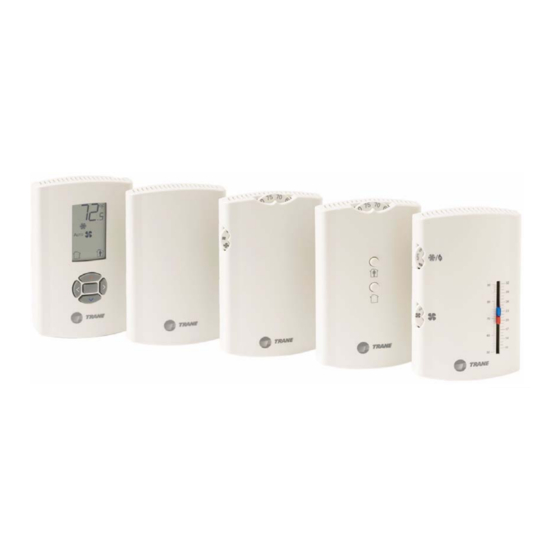
- Page 1 Installation, Operation, and Maintenance Wired Temperature Sensors BAS-SVX10C-EN December 2008...
- Page 2 © 2008 Trane All rights reserved This document and the information in it are the property of Trane and may not be used or reproduced in whole or in part, without the written permission of Trane. Trane reserves the right to revise this publication at any time and to make changes to its content without obligation to notify any person of such revision or change.
-
Page 3: Table Of Contents
Table of Contents General Information ........... . 5 Product Description . - Page 4 Requesting Temporary Occupancy ......28 Error codes ..........28 Lock Symbol .
-
Page 5: General Information
General Information This section provides a description of the wired temperature sensors, as well as part numbers and dimensions. Product Description Note: The information in this manual applies to both factory and field installed versions of Trane wired temperature sensors. -
Page 6: Part Numbers
General Information Part Numbers The following table lists part numbers for each sensor type. Features Global Sensor type Setpoint control System Occupancy LEDs Part number BAYSENS parts Single X1351152701 BAYSENS074A SEN01447 X1351152801 BAYSENS077A SEN01448 Temperature sensors Single X1351152901 BAYSENS075A SEN01449 X1351153001 BAYSENS073A SEN01450... -
Page 7: Dimensions
General Information Dimensions The following illustration provides specific dimension details. The dimensions are the same for all models. TYP R.07 in (R1.9) mm) 0.31 in (8 mm) TYP 0.24 in (6 mm) 2.9 in (73.5 cm) 1.08 in (27.5 mm) 0.12 in (3 mm) 3.39 in (86 mm) 2.48 in (63 mm) -
Page 8: Pre-Installation
Pre-Installation This section provides the following pre-installation information: • Location considerations • Height requirements • Mounting surfaces Location Considerations Placement of the sensor is critical to proper operation. When selecting a location, avoid the following: • Areas of direct sunlight •... -
Page 9: Installation And Configuration: Display Sensor
Installation and Configuration: Display Sensor This section provides step-by-step installation instructions for the display sensor (see applicable part numbers for the temperature sensor with LCD display on p. 6). For installation of all other sensor models, see Read through the pre-installation information(p. -
Page 10: Wiring The Sensor
4. If the terminal block was removed from the circuit board, attach it to the pins inside the sensor cover (Figure Figure 1. Attaching the terminal block to the pins on the circuit board RJ11 (RJ22 compatible) connection for a Trane 24 VAC/VDC service tool (GROUND) COMM–... -
Page 11: Configuring The Display Sensor
Installation and Configuration: Display Sensor Configuring the Display Sensor The configuration of the display sensor determines which system features can be accessed and changes can be made by the tenant (for example, changes to cooling/heating mode, setpoint, or fan speed. Verify system and associated unit features before configuring the sensor. The building owner or operator may choose to limit tenant access to certain features. - Page 12 Installation and Configuration: Display Sensor 1. Press the center button on the keypad to begin the configuration process. Center button 2. Configure the sensor options in the order shown in the table. • Press to scroll to the next selection (as illustrated). •...
- Page 13 Installation and Configuration: Display Sensor Setting Configuration options System (continued) b) Dual setpoint emergency heat/ heat/cool/ emergency heat/ heat/cool/auto/off auto/off heat/cool/off c) No setpoint no system options enabled Note: Not all fan options are available for all systems. auto/off auto/off/ auto/off/low auto/high (on) low/high...
- Page 14 Installation and Configuration: Display Sensor 1. Review the display to ensure that you have selected the correct configuration options. The example shows a display that has been configured for: • Dual setpoint • Temperature units (Fahrenheit) • Temperature resolution to tenths of a degree •...
-
Page 15: Optional Configuration Features
Installation and Configuration: Display Sensor Optional Configuration Features Displaying Setpoint or Temperature You can configure the sensor to display either the temperature (default) or setpoint. To select either option: 1. Verify that the sensor is in operating mode and at the home screen. 2. -
Page 16: Replacing The Cover
Installation and Configuration: Display Sensor 3. Press the left and right arrows for 4 seconds. The lock symbol will appear on the display to indicate that the setting has been locked. Note: If you try to access a feature that is locked, the locked symbol appears on the display. -
Page 17: Installation: All Models Other Than The Display Sensor
Installation: All Models Other Than the Display Sensor This section provides step-by-step installation instructions for all sensor models other than the display sensor. (For installation of the display sensor, see 9.) Read through the pre-installation information before proceeding with the installation. Note: Before installing a wired sensor, ensure that a wire access hole is available at the sensor location and the wire is accessible through the hole. - Page 18 Installation: All Models Other Than the Display Sensor 3. Remove the circuit board by pressing the thumb catch on the left side of the board. Use the terminal block to lift the circuit board from the back plate. Thumb catch Terminal block 4.
- Page 19 Installation: All Models Other Than the Display Sensor Circuit board fits under catches Slot on circuit board aligns with tab on back plate BAS-SVX10C-EN...
-
Page 20: Installing The Comm Module (Optional)
Installation: All Models Other Than the Display Sensor Installing the COMM Module (optional) An optional COMM module is available that provides a local RJ22 connection to a Trane service tool for maintenance use. It must be ordered separately. Install the COMM module before wiring the sensor: 1. -
Page 21: Changing The Setpoint Thumb Wheel (Optional)
Installation: All Models Other Than the Display Sensor Changing the Setpoint Thumb Wheel (optional) Sensors with temperature setpoint control have pre-installed Fahrenheit setpoint thumb wheels. A Celsius setpoint thumb wheel is included with these sensors. An optional hot/cold setpoint thumbwheel can be ordered separately. To change the thumb wheel: 1. -
Page 22: Replacing The Cover
Installation: All Models Other Than the Display Sensor Replacing the Cover To replace the cover: 1. Hook the cover over the top of the back plate. Apply light pressure to the bottom of the cover until it snaps in place. 2. -
Page 23: Operation
Operation This section describes sensor operations. Changing Temperature Settings To change temperature settings: • For sensors with temperature setpoint thumb wheels (located on top of the sensor), rotate the thumb wheel to the desired temperature setting. Note: If you need to change or replace a thumb wheel, see “Changing the Setpoint Thumb Wheel (optional), ”... -
Page 24: Selecting Temporary Occupancy (Timed Override)
Operation Selecting Temporary Occupancy (Timed Override) Temporary occupancy (timed override) is available on some sensors. Temporary occupancy can be selected to adjust temperature, fan, or heat/cool settings after the system has changed to unoccupied mode. System control will revert to unoccupied after a pre-determined time period. Note: Not all systems support the occupancy function. -
Page 25: Service Pin Request
Operation Service Pin Request Some sensor models can communicate a service pin request to their connected unit controller. Sensors with Occupied/Unoccupied Buttons To initiate a service pin request, press the Occupied button (Figure 2, p. 24) for 10–25 seconds. The following occurs: Space temperature output is driven to 10 Ω... -
Page 26: Star(*)/Double Star(**) Function
Operation Star(*)/Double Star(**) Function The star/double star function is available on sensor models with thumb wheels and on the display sensor. Note: Consult the appropriate unit controller documentation for information about this function. Sensors with Thumb Wheels Turning the thumb wheel clockwise makes the star(*) visible; turning it counter-clockwise makes the double star(**) visible (see Figure •... -
Page 27: Display Sensor Operation
Operation Display Sensor Operation This section describes display sensor operation. Figure 5 shows an example of a display sensor that has been configured and is in operating mode. Figure 5. Display sensor in operating mode Temperature System settings Fan settings Occupancy indicator/Error code Keypad Changing Temperature Settings... -
Page 28: Changing System Settings
Operation Changing System Settings 1. From the home screen, press . The system setting menu Indicates that the system is in cooling mode. appears. Indicates that the system is in heating mode. 2. Press to choose the desired system setting. 3. -
Page 29: Maintenance And Troubleshooting
Maintenance and Troubleshooting This section describes sensor features that can be used for maintenance and troubleshooting. LEDs Some sensor models have LEDs. They are located on the front cover and convey the following information: The red service LED indicates that service is needed. Service LED (red) •... -
Page 30: Measuring Output Resistance
Maintenance and Troubleshooting Measuring Output Resistance Measure output resistance as follows, according to sensor type. Display Sensors For display sensors, measure the outputs for zone temperature, setpoints, heat setpoint, and system/fan mode as described: 1. Ensure that the GROUND (terminal 10) and the SIGNAL COMMON (terminal 2) wires are grounded to the transformer. - Page 31 Maintenance and Troubleshooting Table 1. Resistance measurements for zone temperature and setpoints Nominal zone temperature Nominal setpoint and heating Zone or setpoint temperature output resistance setpoint output resistance 938 Ω 55°F (12.8°C) 17.47 kΩ 792 Ω 60°F (15.6°C) 15.3 kΩ 695 Ω...
-
Page 32: Cleaning The Sensor
Maintenance and Troubleshooting Cleaning the Sensor NOTICE Equipment damage! Spraying glass cleaner or any other solution directly on the sensor may damage it. You can clean the sensor by applying glass cleaner to a soft, non-abrasive cloth, and gently wiping the face, including the buttons and LCD display. -
Page 33: Wiring Diagrams
Wiring Diagrams Each wiring diagram is identified by sensor part number (see “Part Numbers, ” p. 6 for reference.) For wiring information for the display sensor, see Figure 1, p. X1351152701 R1, 1.5 kΩ Timed Timed override override thermistor, Ω Unoccupied Occupied 10 k... -
Page 34: Temperature Sensors With Fan Control
Wiring Diagrams X1351153001 R1, 1.5 kΩ Zone Timed Timed override RT1 thermistor, temperature override On SW1 Ω 10 k at 25°C Cancel SW2 Signal common Dwg source: 3270 3438 Temperature sensors with fan control X1379084501 R9, 1.5 kW R11, zero W Zone Timed Timed... - Page 35 Wiring Diagrams X1379085101 R9, 1.5 kW R11, zero W Zone Timed Timed override temperature override On SW3 Thermistor, Cancel SW4 10 k at 25°C Signal common Note 1: Temperature Calibration Pot 1 is Setpoint Cool setpoint (CSP) Pot 1 (see Note 1 factory Pot 5,...
- Page 36 Wiring Diagrams X1379084101 RT1 thermistor, Zone R11, zero W 10 k at 25°C temperature Signal common Note 1: Temperature Calibration Pot 1 is setpoint Cool setpoint (CSP) Pot 1 (see Note 1 factory Pot 5, calibrated. 1 kW Mode Field (Fan switch) adjustment voids...
-
Page 37: Temperature Sensors With Fan And System Control
Wiring Diagrams Temperature sensors with fan and RT1 thermistor, Zone Ω R9, zero Ω 10 k at 25°C system control temperature Signal common X1379084701 Note 1: Calibration Cool setpoint Pot 1 and Cool setpoint (CSP) Pot 1 (see Note 1 Pot 4, Pot 2 are 1 kΩ... - Page 38 Wiring Diagrams X1379083701 RT1 thermistor, Zone R11, zero W 10 k at 25°C temperature 1 Signal common Note 1: Calibration Cool setpoint Cool setpoint (CSP) Pot 1 (see Note 1 Pot 1 and Pot 4, Pot 2 are 1 kW Mode factory (Sys/Fan switch)
- Page 39 Wiring Diagrams X1379083901 RT1 thermistor, Zone R11, zero W 10 k at 25°C temperature Signal common Note 1: Temperature Calibration Pot 1 is setpoint Cool setpoint (CSP) Pot 1 (see Note 1 factory Pot 5, calibrated. Mode 1 kW Field (Sys/Fan switch) adjustment voids...
-
Page 40: Optional Comm Module
Wiring Diagrams Optional COMM module X1365146702 COMM Module 1 (–) 2 (+) BAS-SVX10C-EN... -
Page 41: Specifications And Agency Compliance
Specifications and Agency Compliance Specifications Sensor operating temperature From 32°F to 122°F (0°C to 50°C) Storage temperature From -40°F to 185°F (-40°C to 85°C) Storage/operating humidity range 5% to 95% relative humidity (RH), noncondensing Thermistor accuracy 0.2°C at 25°C, 1% Display sensor: 50°F to 89.6°F (10°C to 32°C) Setpoint functional range All other sensors: 45°F to 95°F (7.2°C to 35°C) -
Page 42: Declaration Of Ce Conformity
Specifications and Agency Compliance CE Declaration of Conformity Manufacturer: Trane, 4833 White Bear Parkway, Saint Paul, MN 55103, USA Product: Wired display sensor Model number: X1379088601, X1379088604, X1379088605 The manufacturer hereby declares that the product conforms to the following: Electromagnetic Emission:... - Page 43 Specifications and Agency Compliance BAS-SVX10C-EN...
- Page 44 Supersedes BAS-SVX10B-EN (March 2008) www.trane.com Trane has a policy of continuous product and product data improvement and reserves the right to For more information, contact your local Trane office or e-mail us at comfort@trane.com change design and specifications without notice.
Need help?
Do you have a question about the Wired Temperature Sensors and is the answer not in the manual?
Questions and answers