Trane WZS Installation & Operation Manual
Wireless zone sensor
Hide thumbs
Also See for WZS:
- Installation, operation and maintenance manual (52 pages) ,
- Installation, operation and maintenance manual (52 pages) ,
- Installation, operation and maintenance manual (37 pages)

Related Manuals for Trane WZS


Summary of Contents for Trane WZS
- Page 1 Installation, operation, and maintenance Wireless Zone Sensor Model WZS BAS-SVX04A-EN June 2006...
- Page 3 Although Trane has tested the hardware and software described in this guide, no guarantee is offered that the hardware and software are error free. Trane reserves the right to revise this publication at any time and to make changes to its content without obligation to notify any person of such revision or change.
-
Page 4: Warnings And Cautions
Warnings and Cautions Warnings and Cautions. Notice that warnings and cautions appear at appropriate intervals throughout this manual. Warnings are provided to alert installing contractors to potential hazards that could result in personal injury or death, while cautions are designed to alert personnel to conditions that could result in equipment damage. -
Page 5: Table Of Contents
Contents Product Description ..........9 Overview . - Page 6 Contents Output Failure Modes of Operation ....... . . 39 Output Default Mode .
- Page 7 Literature Change History Document Number Date Description BAS-SVX04A-EN June 2006 BAS-SVX04A-EN...
- Page 8 BAS-SVX04A-EN...
-
Page 9: Product Description
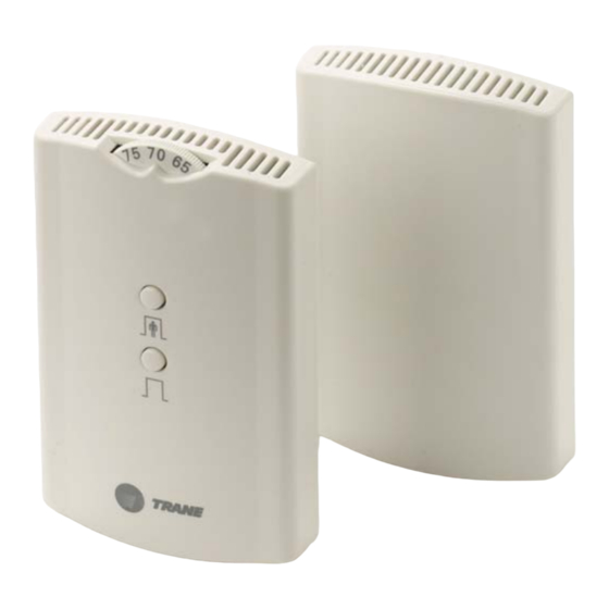
Wireless Zone Sensor system. Overview The Trane Wireless Zone Sensor set includes a sensor and a receiver that work together to provide the same functions as the equivalent Trane wired sensor (#4190-1090), such as the standard 10 kΩ temperature input (with the exception of the communication jack). - Page 10 Product Description Figure 1. Outside dimensions for sensor and receiver 1.08 in (2.75 cm) 2.90 in (7.35 cm) 4.78 in (12.14 cm) 2.62 in (6.65 cm) Note: The dimensions are the same for both the sensor and the receiver. Wireless Zone Sensor • BAS-SVX04A-EN...
- Page 11 Product Description Figure 2. Mounting hole dimensions for sensor and receiver 3.27 in (8.30 cm) 2.36 in (6.00 cm) 1.34 in (3.41 cm) Note: The dimensions are the same for both the sensor and the receiver. BAS-SVX04A-EN • Wireless Zone Sensor...
- Page 12 Product Description Wireless Zone Sensor • BAS-SVX04A-EN...
-
Page 13: Setting The Address, Mounting, Wiring, And Associating The Receiver And Sensor
Setting the Address, Mounting, Wiring, and Associating the Receiver and Sensor The following procedure list shows the recommended order for installation: • Choosing a location for mounting the receiver and sensor • Setting the rotary switches on the receiver and the sensor •... -
Page 14: Location Considerations For The Sensor
Setting the Address, Mounting, Wiring, and Associating the Receiver and Sensor Radio transmission considerations • Avoid metal barriers between the receiver and the sensor; they decrease radio signal quality significantly (for example, plastered walls with metal lathe or metal roof decks). •... -
Page 15: Setting The Rotary Address Switches On The Receiver And The Sensor
Setting the Address, Mounting, Wiring, and Associating the Receiver and Sensor Setting the Rotary Address Switches on the Receiver and the Sensor Note: To expedite the installation and association process, set the addresses before applying power to the receiver. The process of establishing communication between the receiver and sensor is referred to as association. -
Page 16: Setting The Receiver Address
Setting the Address, Mounting, Wiring, and Associating the Receiver and Sensor Setting the Receiver Address Using a small screwdriver, set the three rotary address switches (locations S1, S2, S3) on the receiver (Figure 3, p. 15) to an address between 001 and 999. -
Page 17: Mounting The Base Plate Of The Receiver
Setting the Address, Mounting, Wiring, and Associating the Receiver and Sensor Mounting the Base Plate of the Receiver The receiver consists of two parts: the base plate and the cover (which includes the electronics). Remove the cover: While grasping the top and bottom of the base plate, firmly depress the thumb tab at the bottom of the cover. -
Page 18: Wiring The Receiver To The Unit Controller
Setting the Address, Mounting, Wiring, and Associating the Receiver and Sensor Wiring the Receiver to the Unit Controller Power Requirements The required power for the receiver is 24 Vac or 24 Vdc and is less than 1 VA. The receiver is designed to be powered by the host unit controller. Note: A dedicated transformer is not necessary or advised. - Page 19 Setting the Address, Mounting, Wiring, and Associating the Receiver and Sensor Table 2. Wiring harness: Wire identification Wire label Color Function HEATING SET Not used. For future use. FAN/SYSTEM Not used. For future use. SETPOINT Space temperature setpoint ZONE White Zone temperature GND-SIGNAL Black...
- Page 20 Setting the Address, Mounting, Wiring, and Associating the Receiver and Sensor Figure 6. Example of wiring a receiver to a unit controller with wires routed through the slot in the bottom of the cover Wireless Zone Sensor • BAS-SVX04A-EN...
- Page 21 Setting the Address, Mounting, Wiring, and Associating the Receiver and Sensor Figure 7. Example of wiring a receiver to a unit controller with wires routed through the opening in the back of the base plate BAS-SVX04A-EN • Wireless Zone Sensor...
-
Page 22: Transformer Wiring
Setting the Address, Mounting, Wiring, and Associating the Receiver and Sensor Transformer Wiring Figure 8 shows a wiring diagram using a single transformer to power the unit controller and the receiver. This is the recommended method of installation. Figure 8. Single transformer wiring (recommended) Wireless Zone Sensor •... - Page 23 Setting the Address, Mounting, Wiring, and Associating the Receiver and Sensor Using a dedicated transformer to power the receiver is seldom necessary and is not advised. (See Figure 8, p. 22 for the recommended single transformer wiring method.) A dedicated transformer should be used only when the host transformer does not have enough volt-ampere (VA) capacity to power the receiver (seeTable 11, p.
-
Page 24: Replacing And Securing The Receiver Cover
Setting the Address, Mounting, Wiring, and Associating the Receiver and Sensor Replacing and Securing the Receiver Cover To replace the receiver cover on the base plate, hook the cover over the top of the base plate. Apply light pressure to the bottom of the cover until it snaps in place. -
Page 25: Applying Power To The Receiver
Setting the Address, Mounting, Wiring, and Associating the Receiver and Sensor Applying Power to the Receiver Restore power to the UCM. Observe LED5 on the receiver (Figure 11). It will light and stay constantly On when 24 V power is normal. Figure 11. -
Page 26: Powering The Sensor And Associating The Sensor To The Receiver
Setting the Address, Mounting, Wiring, and Associating the Receiver and Sensor Powering the Sensor and Associating the Sensor to the Receiver Verify that the sensor is set to the same address as the receiver it is to be associated with. 2. -
Page 27: Testing Signal And Battery Strength
Setting the Address, Mounting, Wiring, and Associating the Receiver and Sensor Testing Signal and Battery Strength The following recommended test indicates signal and battery strength. It verifies that the association process was successful and that the batteries have adequate charge. (For more information on LEDs, see “Operation, Maintenance, and Troubleshooting”... -
Page 28: Automatic Association
Setting the Address, Mounting, Wiring, and Associating the Receiver and Sensor Automatic Association When the sensor powers up for the first time, (when the insulation barrier is removed), association between the receiver and the sensor is automatically attempted. If the first association attempt is unsuccessful, the sensor will automatically re- attempt association with the receiver every 10 minutes. -
Page 29: Mounting The Base Plate Of The Sensor
Setting the Address, Mounting, Wiring, and Associating the Receiver and Sensor Mounting the Base Plate of the Sensor Mount the base plate of the sensor directly to any flat surface, including sheet rock or a standard 2 in. x 4 in. electrical box, at a maximum height of 54 in. above the floor. -
Page 30: To Mount Sensor Directly To An Electrical Junction Box
Setting the Address, Mounting, Wiring, and Associating the Receiver and Sensor To Mount Sensor Directly to an Electrical Junction Box Fasten the base plate to the vertically mounted electrical junction box using the two supplied 6-32 x 3/4 in. mounting screws. Note: The sensor must be mounted plumb (vertically level) to ensure proper air movement through the sensor and to ensure accurate temperature control. -
Page 31: Operation, Maintenance, And Troubleshooting
Operation, Maintenance, and Troubleshooting LED Operation The sensor and receiver each have four LEDs (LED1, LED2, LED3, and LED5). The sensor also has a Test button (S5). See Figure 17 for their locations. Figure 17. Wireless zone sensor set components with base plates removed LED1 LED1 LED2... -
Page 32: Signal Quality Test
Operation, Maintenance, and Troubleshooting Signal Quality Test Pressing the Test button (S5) on the sensor initiates a signal quality test. LED1, LED2, and LED3 respond by indicating excellent, marginal, or poor signal quality. The LEDs can be observed on both the sensor (Table 3) and the receiver (Table... -
Page 33: Diagnostics
Operation, Maintenance, and Troubleshooting Diagnostics LED1, LED2, and LED3 will respond to diagnostics by exhibiting specific blinking patterns. They will occur on the sensor as a result of pressing the Test button (S5) (Table 5). They will occur on the receiver independently of any user action (Table Table 5. -
Page 34: Sensor Battery Status Test And Low Battery Power Notification
Operation, Maintenance, and Troubleshooting Sensor Battery Status Test and Low Battery Power Notification LED5 indicates battery status. LED5 is: • Located on the sensor • Bi-color (green/red) • Normally Off Testing is initiated by pressing the Test button (S5). When the battery power goes below a certain threshold, LED5 is automatically activated. -
Page 35: Sensor Batteries
Recharging can cause battery leakage or, in some cases, can cause Equipment Damage! the safety release vent to open. CAUTION Do not attempt to hook up the WZS to a power supply. Equipment damage may result. Equipment Damage! Use non-rechargeable 1.5 volt AA lithium batteries in the sensor. Two batteries are required. -
Page 36: Battery Life
Operation, Maintenance, and Troubleshooting Battery Life Battery life is five years under normal conditions. If the battery is not used for an extended period of time, either remove the batteries or set the sensor address to 000 and press the Test button (S5). This will place the sensor into a low-power hibernation mode. -
Page 37: Occupied (On)/Unoccupied (Cancel) Button Operation
Consult the appropriate unit control module literature for information about this function. ® Comm5 is Trane’s implementation of LonTalk Figure 19. Sensor: Location of Occupied button, Unoccupied button, and star (*) and double star (**) on thumb wheel ** on thumb wheel... -
Page 38: Special Thumbwheel Operation
Operation, Maintenance, and Troubleshooting Special Thumbwheel Operation The Wireless Zone Sensor set supports star (*) and double star (**) on the sensor thumb wheel (Figure 19, p. 37). Note: Consult the appropriate unit control module for information about this function. Using the Wireless Zone Sensor System as a Site Survey Tool to Check Signal Quality Follow these steps to check the signal quality on a site:... -
Page 39: Output Failure Modes Of Operation
Operation, Maintenance, and Troubleshooting Output Failure Modes of Operation Table 9. Output failure modes of operation Zone temperature Situation output Zone setpoint output Receiver address = 000 11.17 kΩ, 72.5°F (22.5°C), 451 Ω, 72.5°F (22.5°C), indefinitely indefinitely Receiver address = 001 to 999 11.17 kΩ, 72.5°F (22.5°C) 451 Ω, 72.5°F (22.5°C) Receiver has powered up, but... -
Page 40: Measuring Output Resistance
Operation, Maintenance, and Troubleshooting Measuring Output Resistance To measure the resistance of the receiver outputs: Make sure the black wire (GNS-SIGNAL) and the yellow wire (GND-POWER) are grounded (see Figure 8, p. 22 Figure 9, p. 23 for wiring diagrams). 2. -
Page 41: Receiver Power-Up Sequence
Operation, Maintenance, and Troubleshooting Receiver Power-up Sequence When power is applied to the receiver, the following sequences occur. They are dependent on the rotary switch address setting and on the association status of the receiver. Address set to 000 and receiver is not associated with a sensor •... -
Page 42: Sensor Transmission Time And Temperature Variables
Operation, Maintenance, and Troubleshooting Sensor Transmission Time and Temperature Variables Time Variables • The maximum time between sensor temperature transmissions is 15 minutes. • The minimum time between sensor temperature transmissions is 30 seconds. • The minimum time for transmitting temperature setpoint changes is 10 seconds. -
Page 43: Servicing And Testing
Operation, Maintenance, and Troubleshooting Servicing and Testing If the wireless zone sensor system is not working as expected, use the tools and procedure described in this section. Servicing and Testing Tools No special tools or software are necessary to service and test the wireless zone sensor system. -
Page 44: Returning A Sensor To Its Factory Defaults
Operation, Maintenance, and Troubleshooting Returning a Sensor to its Factory Defaults To return a sensor to its factory defaults, set the device address to 000. (For more information about setting the address to 000, see “Setting the Sensor Address, ” p. 16.) Press the Test button (S5) on the sensor to force the sensor to read the address switches. -
Page 45: Specifications And Agency Compliance
Specifications and Agency Compliance Specifications Table 11. Wireless Zone Sensor system specifications Sensor operating temperature 32 to 122ºF (0 to 50ºC) Receiver operating temperature -40 to 158ºF (-40 to 70ºC) Storage temperature -40 to 185ºF (-40 to 85°C) Storage and operating humidity range 5% to 95%, non-condensing Accuracy 0.5 °F over a range of 55 to 85°F (12.8 to... -
Page 46: Agency Compliance
Specifications and Agency Compliance Agency Compliance Table 12. Agency compliance for the Wireless Zone Sensor system United States compliance UL listed: UL 94-5VA Flammability rating UL 916: Energy management equipment FCC CFR47, Section 15.247 & Subpart E Digital Modulation Transmission with no SAR (FCC Identification TFP-13651127) This device complies with Part 15 of the FCC Rules. - Page 47 Societe Trane (Epinal, France) 1, rue des Ameriques, B.P . 6 F-88191 Golbey Cedex, France Phone: (33) 329.31.73.00 Fax: (33) 329.81.24.98 This document validates CE conformity of the Trane Wireless Zone Sensor system, sensor module. BAS-SVX04A-EN • Wireless Zone Sensor...
- Page 48 Societe Trane (Epinal, France) 1, rue des Ameriques, B.P . 6 F-88191 Golbey Cedex, France Phone: (33) 329.31.73.00 Fax: (33) 329.81.24.98 This document validates CE conformity of the Trane Wireless Zone Sensor system, receiver module. Wireless Zone Sensor • BAS-SVX04A-EN...
- Page 49 Specifications and Agency Compliance BAS-SVX04A-EN • Wireless Zone Sensor...
- Page 50 Stocking Location Electronic only www.trane.com For more information, contact your local Trane Trane has a policy of continuous product and product data improvement and reserves the right to office or e-mail us at comfort@trane.com change design and specifications without notice.
Need help?
Do you have a question about the WZS and is the answer not in the manual?
Questions and answers