Trane WDS Installation, Operation And Maintenance Manual
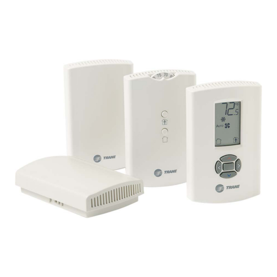
Wireless sensors
Hide thumbs
Also See for WDS:
- Installation, operation and maintenance manual (52 pages) ,
- Installation, operation and maintenance manual (37 pages)

Related Manuals for Trane WDS


Summary of Contents for Trane WDS
- Page 1 Installation, Operation, and Maintenance Wireless Sensors Models WTS, WZS, and WDS BAS-SVX04C-EN April 2008...
- Page 2 © 2008 Trane All rights reserved This document and the information in it are the property of Trane and may not be used or reproduced in whole or in part, without the written permission of Trane. Trane reserves the right to revise this publication at any time and to make changes to its content without obligation to notify any person of such revision or change.
-
Page 3: Table Of Contents
Model WDS Sensor ........ - Page 4 Operating Mode (Model WDS) ........
- Page 5 Contents Appendix B: Agency Compliance ........50 BAS-SVX04C-EN •...
-
Page 7: General Information
® Trane wireless sensor sets are compatible with any Trane unit controller that uses a standard 10 kΩ temperature input. The sets include sensor, receiver, wiring harness, and two AA lithium batteries. No further software or hardware is necessary for site evaluation, installation, or maintenance. -
Page 8: Part Numbers
Part Numbers The following table lists available models by part number: Part number Description X1379082101 Model WTS sensor only X1379082201 Model WDS sensor only X1379082301 Model WTS sensor set X1379082401 Model WDS sensor set X13790492 Model WZS, sensor only, Fahrenheit... -
Page 9: Dimensions
General Information Dimensions The following illustration provides specific dimension details. The dimensions are the same for all models. TYP R.07 in (R1.9) mm) 0.31 in (8 mm) TYP 0.24 in (6 mm) 2.9 in (73.5 cm) 1.08 in (27.5 mm) 0.12 in (3 mm) 3.39 in (86 mm) 2.48 in (63 mm) -
Page 10: Pre-Installation
Pre-Installation This section provides the following pre-installation information: • Location considerations • Height requirements • Mounting surfaces • Address settings Location Considerations Placement of the sensor and the receiver is critical to proper operation. For most installations, barriers limit proper radio signal strength more than distance. For best radio transmission range and reliability, mount the receiver and sensor in line of sight. -
Page 11: Height Requirements
Pre-Installation • High traffic areas (to reduce accidental damage or tampering) • Metal barriers between the receiver and the sensor (for example, plastered walls with metal lathe or metal roof decks) • Thick, solid concrete walls between the receiver and the sensor •... - Page 12 Pre-Installation To set the receiver and sensor addresses: 1. Using a small screwdriver, set the three rotary address switches (locations S1, S2, S3) on the receiver to an address between 001 and 999 (see Figure 1). (You do not have to remove the covers to access the rotary address switches.) Note: Do not use 000 as an address.
-
Page 13: Installation
Installation This section provides step-by-step installation instructions. Read through the pre- installation information before proceeding with installation. Important: It is recommended that you install the sensor set in the order presented in this section. Mounting the Receiver Back Plate To mount the receiver back plate: 1. -
Page 14: Wiring The Receiver To The Unit Controller
Installation Wiring the Receiver to the Unit Controller Power requirements and wiring instructions for the receiver are described in this section. Power Requirements The required power for the receiver is 24 Vac or 24 Vdc and less than 1 VA. The receiver is designed to be powered by the host unit controller. - Page 15 Wire label Color Function HEATING SET Brown Space temperature heating setpoint (WDS only) FAN SYSTEM Green Fan and system control (WDS only) SETPOINT Space temperature setpoint (WDS and WZS only) ZONE White Zone temperature GND-SIGNAL Black Ground for setpoint and zone signal...
- Page 16 Installation Figure 3. Wiring a receiver to a unit controller through the opening in the back of the receiver back plate Figure 4. Wiring a receiver to a unit controller through the bottom slot in receiver cover Wireless Sensors • BAS-SVX04C-EN...
-
Page 17: Replacing The Receiver Cover
Installation Replacing the Receiver Cover To replace the cover: 1. Hook the cover over the top of the back plate. Apply light pressure to the bottom of the cover until it snaps in place. 2. Install the security screw into the bottom of the cover. Security screw Applying Power to the Receiver Restore power to the UCM. -
Page 18: Observing The Receiver For Readiness To Associate
Installation Observing the Receiver for Readiness to Associate After initial power up, the receiver conducts a channel scan for 20 seconds. During this time, the receiver selects from 16 available channels the clearest channel on which to operate. LED1, LED2, and LED3 flash rapidly in succession (round-robin style) while the channel scan is in progress, as shown in part 1 of the illustration. -
Page 19: Associating The Sensor To The Receiver
Installation Associating the Sensor to the Receiver To associate the sensor to the receiver: 1. Remove the sensor cover by firmly pressing the thumb tab at the bottom of the cover and pulling the cover away from the back plate. 2. -
Page 20: Testing Signal Strength And Battery Status
WTS and WZS sensors.) Note: The LEDs will turn Off after 5 seconds to conserve battery strength. For model WDS, determine the signal strength and battery status by viewing the symbols on the sensor display. (See the illustration for model WDS sensors.) 3. -
Page 21: Mounting The Sensor Back Plate
Installation Mounting the Sensor Back Plate To mount the sensor back plate: Hold the back plate against the mounting surface and mark the screw locations. 2. Secure the back plate against the mounting surface using included hardware. The figure shows an example of mounting the back plate of the sensor into sheetrock or plaster. -
Page 22: Configuring The Wireless Sensor (Model Wds Only)
Configuration Procedure To configure settings on the model WDS sensor, follow this procedure in the order presented. 1. Press the configuration button for 3 seconds. - Page 23 Installation 1. Press the center button on the keypad to begin the configuration process. Center button 2. Configure the sensor options in the order shown in the table. • Press to scroll to the next selection (as illustrated). • Press to move to the next menu (as illustrated).
- Page 24 Installation Setting Configuration options System (continued) b) Dual setpoint emergency heat/ heat/cool/ emergency heat/ heat/cool/auto/off auto/off heat/cool/off c) No setpoint no system options enabled Note: Not all fan options are available for all systems. auto/off auto/off/ auto/off/low auto/high (on) low/high med/high off/high (on) off/low/high...
- Page 25 Installation 3. Review the display to ensure that you have selected the correct configuration options. The example shows a display that has been configured for: • Dual setpoint • Temperature units (Fahrenheit) • Temperature resolution to tenths of a degree •...
-
Page 26: Optional Features
Installation Optional Features Displaying Setpoint or Temperature You can configure the sensor to display either the temperature (default) or setpoint. To select either option: 1. Verify that the sensor is in operating mode and at the home screen. 2. Press the up and down arrows for 3 seconds. The arrow indicates setpoint display, as shown in the illustration. -
Page 27: Replacing The Sensor Cover
Installation 3. Press the left and right arrows for 4 seconds. Note: If you try to access a feature that is locked, the locked symbol will appear on the display. If you press a keypad button to try change a locked setting, the locked symbol will flash. -
Page 28: Operation
This section describes sensor operations. Temporary Occupancy (Timed Override) Temporary occupancy (timed override) is available on models WDS and WZS. Temporary occupancy is selected for after-business-hours adjustment of temperature setting, fan settings, or heat/cool settings, when the system has changed to unoccupied mode. -
Page 29: Service Pin Request
Operation Service Pin Request Model WZS and WDS sensors can communicate a service pin request to their associated receivers. Model WZS Sensor To initiate a service pin request, press the Occupied button (Figure 5, p. 28) for 10–25 seconds. The following occurs: Space temperature output is driven to 10 Ω... -
Page 30: Star(*)/Double Star(**) Function
** on thumb wheel (* is hidden from view) The WDS sensor set supports star(*) and double star(**) functions if the sensor is configured for single setpoint operation. Press the up or down arrow on the keypad to display the star(*) or double star(**), respectively, on the sensor display. -
Page 31: Receiver Power-Up Sequence
LED5 is constantly On, indicating power is applied and the receiver is functional. • All models: Zone temperature and cooling setpoint default to 72.5°F (22.5°C). WDS only: The heating setpoint defaults to 70.5°F (21.4°C) and the fan/system output will be 2230 Ω (see “Output Values—Failure and Default Modes of Operation, ”... -
Page 32: Sensor Transmission Time And Temperature Variables
Operating Mode (Model WDS) This section describes how to operate the Trane wireless sensor, model WDS. Figure 8 shows an example of a model WDS that has been configured and is in operating mode. Figure 8. Wireless sensor (model WDS) in operating mode... -
Page 33: Changing Room Temperature
Operation Changing Room Temperature This symbol shows the current room 1. To increase the room temperature, press temperature, or your setpoint selection To decrease the room temperature, press while you are making an adjustment. When you select a setpoint, this symbol 2. -
Page 34: Requesting Temporary Occupancy
Replace batteries. Flashing symbol Use only UL-listed non-rechargeable indicates that 1.5 V lithium AA batteries (Trane p/n approximately 14 days of operation remain. X13770035010 or equivalent). Wireless Sensors • BAS-SVX04C-EN... -
Page 35: Maintenance And Troubleshooting
LED5 The sensor for models WTS and WZS have four LEDs: LED1, LED2, LED3, and LED5. The sensor for model WDS has test symbols and error codes that appear on the display. All three sensor models have a Test button. -
Page 36: Diagnostics
View their response by pressing the Test button. (See Table Error codes appear on the display of the model WDS sensor when diagnostics occur. (See Table Table 2. Diagnostics on the sensor LED state when Test button is pressed... -
Page 37: Testing Signal Strength
(Table 4) and the receiver (Table 5, p. 38). • Model WDS: Test symbols on the sensor display indicate signal strength (Table LED1, LED2, and LED3, on the receiver, respond by indicating signal strength (Table 5, 38). Table 4. Observing signal strength on the sensor... -
Page 38: Testing Battery Status
35). LED5 on the sensor responds by indicating the level of battery strength, as shown in Table • On model WDS, push the Test button on the sensor (see location on Figure 10, p. 35). In response, a battery test symbol appears on the display. The symbol shown indicates battery life expectancy (see Table 7, p. -
Page 39: 24 V Power Status Indicator
Maintenance and Troubleshooting Table 7. Battery status: Battery symbol on model WDS sensor display Battery test User action symbol Indicates... Press Test Full battery power. button 50% battery life left. 25% battery life left. Replace batteries. Flashing symbol indicates that approximately 14 days of operation remain before the battery is too weak to power the sensor. -
Page 40: Replacing Sensor Batteries
If lithium batteries are temporarily unavailable, alkaline batteries can be used. However, alkaline battery life is very short by comparison. • The battery life for a model WDS may decrease with extended LCD display activity. Battery Installation WARNING Prevent Injury! Batteries can explode or leak and cause burns if installed backwards, disassembled, charged, or exposed to water, fire, or high temperature. -
Page 41: Manual Association
Maintenance and Troubleshooting 1. Observe the polarity indicators that are molded into the cover. 2. Install two batteries (of the type specified in “Battery Type, ” p. 40) in the battery- holding slot that is molded into the sensor cover. The sensor has been designed to prevent damage if the batteries are installed backwards, to reduce the potential for injury. -
Page 42: Sensor/Receiver Compatibility
3. Apply power to the new device. Association between the new and the remaining devices will automatically occur. Notes: When replacing a WDS sensor, the receiver (version 1.5 or higher) will automatically configure the sensor to match the last stored configuration, if the sensor has not been placed into configuration mode and the factory default configuration is still valid. -
Page 43: Procedure For Testing The Wireless Sensor System
Note: When checking signal strength, both LED1 and LED3 on the receiver and sensor illuminate in unison if the sensor and receiver are associated. Use this feature to confirm association. • Model WDS: Battery life (“Testing Battery Status, ” p. 34) and signal strength (“Testing Signal Strength, ” p. -
Page 44: Output Values-Failure And Default Modes Of Operation
SETPOINT (red) or ZONE (white) wire. Compare resistance measurements to those in Table b. WDS only: Measure between the grounded GND-SIGNAL (black) wire and the FAN/SYSTEM (green) wire. Compare resistance measurements to those given in Table Wireless Sensors • BAS-SVX04C-EN... - Page 45 10.5 kΩ 403 Ω 80°F (26.7°C 9.3 kΩ 305 Ω 85°F (29.4°C) 8.25 kΩ 208 Ω Table 9. Receiver resistance table for model WDS Nominal output Fan command System command resistance Auto or invalid Emergency heat 35,000 Ω Auto or invalid Heat 19,480 Ω...
-
Page 46: Cleaning The Sensor
Avoid inadvertent pressing of the Occupied/Unoccupied buttons on the model WZS sensor or the keypad on the WDS sensor, as this may result in an unwanted timed override or settings change. -
Page 47: Specifications
0.25ºF when outside this range Setpoint functional range (WZS only) 45 to 95ºF (7.22 to 35ºC) Setpoint functional range (WDS only) 50 to 89.6ºF (10 to 32ºC) Setpoint thumb wheel markings (WZS only) 50 to 85ºF (stamped every 5ºF) and *, ** 11 to 29ºC (stamped every 3ºC) and *, **... -
Page 48: Appendix A: Wiring Diagrams
Appendix A: Wiring Diagrams Single Transformer Wiring Typically, a single transformer powers the unit controller, which provides power to the receiver. This is the recommended method of wiring. Wireless Sensors • BAS-SVX04C-EN... -
Page 49: Multiple Transformer Wiring
Appendix A: Wiring Diagrams Multiple Transformer Wiring WARNING Shock Hazard! If the use of multiple transformers is necessary, locate them so that they do not allow simultaneous human contact. Touching both 24 Vac outputs simultaneously on two electrically connected transformers could result in death or serious injury. Using a dedicated transformer to power the receiver is seldom necessary and is not advised. - Page 50 Appendix B: Agency Compliance The following table presents agency compliance information for wireless sensor set models as shown. United States compliance UL listed:UL 94-5VA Flammability rating (all models) UL 916: Energy management equipment FCC CFR47, Section 15.247 & Subpart E Digital Modulation Transmission with no SAR (FCC Identification TFP-13651127) This device complies with Part 15 of the FCC Rules.
- Page 52 Date April 2008 Supersedes www.trane.com Trane has a policy of continuous product and product data improvement and reserves the right to For more information, contact your local Trane change design and specifications without notice. office or e-mail us at comfort@trane.com...
Need help?
Do you have a question about the WDS and is the answer not in the manual?
Questions and answers