Table of Contents
Advertisement
Quick Links
Installation, Operation, and Maintenance
Remote-Mounted Medium Voltage
Air-Cooled
Adaptive Frequency™ Drive
with Tracer AdaptiView™ Control
Model:
VFDB
Only qualified personnel should install and service the equipment. The installation, starting up, and servicing of
heating, ventilating, and air-conditioning equipment can be hazardous and requires specific knowledge and training.
Improperly installed, adjusted or altered equipment by an unqualified person could result in death or serious injury.
When working on the equipment, observe all precautions in the literature and on the tags, stickers, and labels that are
attached to the equipment.
May 2022
Adaptive Frequency
TM
Drive for Chillers
SAFETY WARNING
VFDB-SVX001A-EN
Adaptive Frequency
TM
Drive for Chillers
Advertisement
Table of Contents
Troubleshooting

Subscribe to Our Youtube Channel
Related Manuals for Trane Adaptive Frequency VFDB


Summary of Contents for Trane Adaptive Frequency VFDB
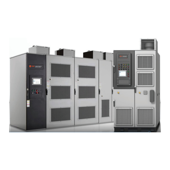
- Page 1 Installation, Operation, and Maintenance Remote-Mounted Medium Voltage Air-Cooled Adaptive Frequency™ Drive with Tracer AdaptiView™ Control Adaptive Frequency Drive for Chillers Adaptive Frequency Drive for Chillers Model: VFDB SAFETY WARNING Only qualified personnel should install and service the equipment. The installation, starting up, and servicing of heating, ventilating, and air-conditioning equipment can be hazardous and requires specific knowledge and training.
-
Page 2: Instructions
Practices requirements for arc flash protection, PRIOR to servicing the unit. NEVER PERFORM ANY Trane believes that responsible refrigerant practices are SWITCHING, DISCONNECTING, OR VOLTAGE important to the environment, our customers, and the air conditioning industry. All technicians who handle TESTING WITHOUT PROPER ELECTRICAL PPE AND ARC FLASH CLOTHING. - Page 3 Copyright This document and the information in it are the property of Trane, and may not be used or reproduced in whole or in part without written permission. Trane reserves the right to revise this publication at any time, and to make changes to its content without obligation to notify any person of such revision or change.
-
Page 4: Table Of Contents
....12 Trane VFDB MV Drive ....49 Parts Ordering Information . - Page 5 Table of Contents PowerFlex “A” or “B” Frame Pre-Commis- sioning Check List ..... 1 Remote-Mounted Medium Voltage Air- Cooled Adaptive Frequency™ Drives: PowerFlex 7000 (Model: AFDJ) PowerFlex 6000T (Model: VFDB) .
-
Page 6: Overview
For variable frequency drives instructions: Unless specified otherwise, disconnect all or other energy storing components provided by Trane electrical power including remote disconnect and or others, refer to the appropriate manufacturer’s... -
Page 7: Ce For Mv Drives
CVHH and CDHH chillers also comply. All Trane-supplied remote starters and drives must be Using a megohm test to perform continuity checks in used with CVHH or CDHH Trane chillers to ensure CE the drive equipment could result in damage to the compliance controller circuitry. -
Page 8: Visual Inspection
WARNING hours of operation, and observe the chiller and drive for any abnormalities. Proper Field Wiring and Grounding Contact Trane technical support for assistance if needed. Required! VFDB Checks Failure to follow code could result in death or serious injury. -
Page 9: Rockwell Medium Voltage Powerflex 6000T Drives
Trane or Rockwell office. Cabinet Voltage Levels Typical Configurations The Trane-supplied Medium Voltage VFDB drives include WARNING two parts: input starter and drive panel. The drive panel is available in two air-cooled versions, called Frames: Hazardous Voltage! 1) 6000T A-Frame, and 2) 6000T B-Frame. -
Page 10: Powerflex 6000T Medium Voltage Cabinet
Follow proper lockout/ tagout procedures to ensure the power cannot be inadvertently energized. For variable frequency drives or other energy storing components provided by Trane or others, refer to the appropriate manufacturer’s literature for allowable waiting periods for discharge of capacitors. -
Page 11: Control Voltage Power De-Energization
Note: For questions regarding these procedures, contact MUST follow precautions in this manual and on the your local Trane or Rockwell office. tags, stickers, and labels, as well as the following • Wear the PPE that is necessary to protect from the instructions: Unless specified otherwise, disconnect all shock and arc flash hazards. -
Page 12: General Information
Parts Ordering Information Refer to the model number printed on the Trane Adaptive Frequency Drive nameplate when ordering replacement parts or service for the drive. When ordering parts, contact the local Trane Parts Office in your area. For service, contact a qualified service organization. -
Page 13: Scope Of Installation And Commissioning Responsibilities
See Figures/Pages Chiller (provided by Trane) — — — Inspect chiller for shipping damage Assist if any questions — — Drive (provided by Trane from Rockwell) Direct ship from — — — Rockwell Inspect drive for shipping damage — —... -
Page 14: About The Vfdb Drive
About the VFDB Drive Drive Identification The VFDB Trane Adaptive Frequency Drive is an air-cooled The drive has a Trane model number and a Rockwell series drive which uses Cascaded “H” Bridge (CHB) topology. number. Both these are extremely important when This topology combines an integrally mounted phase- identifying the drive for service or parts. -
Page 15: Model Number Descriptions
Model Number Descriptions Trane Service Model Digit 15 — VFD Frame Size (SRRL) Number An example of a typical chiller starter model number is: VFDB0035NA0B00CDA Model Number Digit Identification Model number digits are selected and assigned in accordance with the... -
Page 16: Cabinet
Cabinet The cabinet has a NEMA 1 enclosure rating. • Verify that the NEMA 1 enclosure can be kept clean and dry. Environmental Conditions • The area chosen should allow the space required for Important: Location of the VFDB drive is important if proper air flow. - Page 17 Cabinet Table 3. B-Frame weights and heat rejection MAX NUMBER AND SIZE OF CABLES (NEMA) MAX HEAT LINE VOLTAGE- Motor REJECTION LINE TO INPUT INPUT STARTER DRIVE PANEL WEIGHT SRRL FREQUENCY AMPS BTU/HR STARTER TO DRIVE PANEL OUTPUT TO MOTOR FIGURE 251 2300/2400V-60Hz 1180...
- Page 18 Cabinet Figure 2. A-Frame: Top view (VFD 2300/3300/4160V), in. LINE CABLE CONDUIT OPENING LINE CABLE CONDUIT OPENING 8.96 LOAD CABLE CONDUIT OPENING LOAD CABLE CONDUIT OPENING 8.96 (17.1X11.8) (17.1X11.8) 11.71 11.71 44.21 44.21 49.21 49.21 5.02 CONTROL WIRE 5.02 CONTROL WIRE 59.1 59.1 CONDUIT OPENING...
- Page 19 Cabinet Figure 3. A-Frame: Top view (VFD 6600V), in. 16.73 LINE CABLE CONDUIT OPENING 6.89 (9.84X7.87) 10.02 19.64 LOAD CABLE CONDUIT OPENING (9.84X7.87) 45.45 50.80 SERVICE CUT OUT (5.51X17.72) CONTROL WIRE CONDUIT OPENING (3.94X4.92) 5.31 59.1 11.81 16.73 LINE CABLE CONDUIT OPENING 6.89 (9.84X7.87)
- Page 20 Cabinet Figure 4. A-Frame: Front view (VFD 2300/3300/4160V), in. 15.75 15.75 22.05 18.51 1U,1V,1W T1,T2,T3 DISPLAY HAZARDOUS 91.65 91.65 VOLTAGE LABEL GROUND BAR 47.64 63.39 15.75 22.05 91.65 75.20 VFDB-SVX001A-EN...
- Page 21 Cabinet Figure 5. A-Frame: Front view (VFD 6600V), in. 15.75 21.54 1U,1V,1W T1,T2,T3 DISPLAY 91.65 HAZARDOUS VOLTAGE LABEL GROUND BAR 90.94 87.01 15.75 21.54 91.65 110.04 VFDB-SVX001A-EN...
- Page 22 Cabinet Figure 6. A-Frame: Bottom view (VFD 2300/3300/4160V), in. 61.93 42.72 31.69 4.92 1.46 LINE CABLE LINE CABLE CONDUIT CONDUIT OPENING OPENING 47.83 47.83 LOAD CABLE LOAD CABLE 47.07 47.07 CONDUIT CONDUIT OPENING OPENING (8.66X5.63) (8.66X5.63) 14.47 14.47 5.81 5.81 5.24 CONTROL WIRE MOUNTING HOLES...
- Page 23 Cabinet Figure 7. A-Frame: Bottom view (VFD 6600V), in. 87.01 67.32 45.47 CONTROL 23.62 WIRE CONDUIT 3.94 OPENING (3.94X4.13) 49.21 50.21 47.20 41.45 12.89 5.12 LOAD CABLE CONDUIT OPENING 7.58 MOUNTING HOLES FOR (15.75X5.51) 0.71(18.0) DIA. ANCHOR BOLTS 16.02 LINE CABLE CONDUIT OPENING (15.75X5.51) 104.13...
- Page 24 Cabinet Figure 8. A-Frame: Door-swing requirements, in. 90 MAX DOOR SWING H MAX 90 MAX 90 MAX DOOR OPENING DOOR SWING DOOR SWING VFD 2300/3300/4160V 34.73 MAX 90 MAX DOOR OPENING DOOR SWING 90 MAX 90 MAX 90 MAX DOOR SWING DOOR SWING DOOR SWING VFD 6600V...
- Page 25 Cabinet Figure 9. A-Frame: Interior view, major components, in. VFDB-SVX001A-EN...
- Page 26 Cabinet Figure 10. B-Frame: Top view, in. 62.99 35.04 42.91 LINE CABLE 47.05 CONDUIT 55.12 OPENING (5.4X5.4) CONTROL WIRE CONDUIT OPENING (5.4X5.4) LOAD CABLE CONDUIT 6.30 OPENING (5.4X5.4) 140.94 59.1 143.70 62.99 35.04 42.91 LINE CABLE 47.05 CONDUIT 55.12 OPENING (5.4X5.4) CONTROL WIRE CONDUIT OPENING...
- Page 27 Cabinet Figure 11. B-Frame: Front view, in. 15.75 18.50 DISPLAY 91.65 HAZARDOUS VOLTAGE LABEL GROUND BAR 149.61 15.75 18.50 1U,1V,1W 91.65 T1,T2,T3 161.42 VFDB-SVX001A-EN...
- Page 28 Cabinet Figure 12. B-Frame: Bottom view, in. 85.35 60.43 58.07 30.22 28.54 1.26 1.26 LINE CABLE CONDUIT OPENING (5.4X5.4) LOAD CABLE CONDUIT OPENING 55.12 CONTROL (5.4X5.4) WIRE CONDUIT OPENING (5.4X5.4) 19.49 11.28 9.16 6.10 141.28 MOUNTING HOLES FOR 0.72(18) DIA. ANCHOR BOLTS 143.76 97.08 61.69...
- Page 29 Cabinet Figure 13. B-Frame: Door-swing requirements, in. 90.0 MAX 90.0 MAX DOOR SWING DOOR SWING 90.0 MAX 90.0 MAX 90.0 MAX DOOR SWING DOOR SWING DOOR SWING 39.45 MAX 90.0 MAX DOOR OPENING DOOR SWING Figure 14. B-Frame: Interior view, major components VFDB-SVX001A-EN...
- Page 30 Cabinet Figure 15. Input starter: Top view, in. 6.61 5.41 LINE CABLE CONDUIT OPENING (5.68X9.00) 4.64 16.04 30.00 LOAD CABLE CONDUIT OPENING (5.68X9.00) 3.62 CONTROL WIRE CONDUIT OPENING (3.00X3.00) Figure 16. Input starter: Front view, in. 2.48 1.00(25.0)x3.00(76.0) NON-REMOVABLE SILL CHANNELS 90.24 COPPER ONLY LABLE 1U,1V,1W...
- Page 31 Cabinet Figure 17. Input starter: Bottom view, in. LINE CABLE 6.57 CONDUIT OPENING (5.68X9.00) 5.00 9.29 4.45 20.12 32.95 30.00 35.98 LOAD CABLE 4.62 CONDUIT OPENING (5.68X9.00) CONTROL WIRE CONDUIT OPENING (3.00X5.00) 2.30 MOUNTING HOLES FOR 0.50(12.0) DIA, ANCHOR BOLTS 23.68 25.98 Figure 18.
- Page 32 Cabinet Figure 19. Input starter: Interior view, major components VFDB-SVX001A-EN...
-
Page 33: Pre-Installation
Pre-Installation Receipt Inspection Overhead Lifting Immediately upon the drive, inspect the crates for signs of damage. After the crates are offloaded, disassemble the WARNING crating and check for possible shipping damage.Use a Improper Lift or Move! crowbar or other suitable tool to carefully remove the packaging. -
Page 34: Lift The Power Module/Lv Control Cabinet
Pre-Installation Lift the Power Module/LV Control Cabinet Lifting Angles for B-frame Drives The lifting angles hold the Power Module/LV Control Depending on the type of drive frame, or lifting angles cabinets together to prevent separation and damage while must be installed before you can lift the cabinet. riggers move the drive to the final installation area. -
Page 35: Lift Input Starter
Pre-Installation Figure 24. Overhead lifting (isolation transformer Figure 25. Overhead lifting (starting/junction cabinet) cabinet) Steel cable U-rings Lifting Angle pair M12 bolt 45° maximum Washer 45° Minimum height of maximum 1.5 m (5 ft) Minimum height of Lifting provision 1.5 m (5 ft) Storage Lift Input Starter The lifting angles hold the starting/junction cabinet... -
Page 36: Mechanical Installation
Mechanical Installation Install Drive panel drive rating), half along the front edge of the cabinet and half along the rear edge of the cabinet. Access to the interior of the cabinet is required to make these Connect Shipping Splits connections. Access for the front connections requires The standard A-frame for PowerFlex 6000T drives comes only opening the doors. -
Page 37: Affix Cabinets To Floor
Mechanical Installation Figure 27. Secure the cabinets, B-frame Secure with M6 hardware (8 places) 2-socket screw M6x16 Combination pillar Affix Cabinets to Floor Figure 28. Bolt cabinet to steel base, B-frame WARNING Drive Mounting Instructions! Failure to correctly anchor the cabinet could result in M16 bolt Lock washer death or serious injury and equipment damage. -
Page 38: Install Input Starter
Mechanical Installation Install Input Starter Figure 30. Access to power bus with low voltage panel rotated WARNING Hazardous Voltage! Remove self- tapping screws from Failure to disconnect power before servicing could Bus Access Barriers result in death or serious injury. Disconnect all electric power, including remote Swing Open Low disconnects before servicing. -
Page 39: Load Cable Connections
Mechanical Installation Front Access - Bottom Incoming Cables Load Cable Connections 1. Open the power cell door. 1. Complete the Power Lockout procedure. 2. Locate incoming cable duct at rear left-hand side of 2. Remove the appropriate cable conduit opening power cell, refer to below figure. -
Page 40: Install Main Cooling Fans
Mechanical Installation Install Main Cooling Fans Figure 34. Routing of load cables (top exit shown) Main cooling fans are shipped in separate crates. The fans are shipped assembled in the fan housing, but must be installed after siting the drive. 1. - Page 41 Mechanical Installation Figure 36. Main cooling fan housing, A-frame (6...6.6 kV) Fan wiring terminals located behind this cover Mount fan assembly with M6 hardware across the front of the fan assembly Front View Back flange of fan Top plate bracket assembly Back View VFDB-SVX001A-EN...
-
Page 42: Wiring
For variable frequency drives 0.75 or other energy storing components provided by Trane or others, refer to the appropriate manufacturer’s literature for allowable waiting periods for discharge of capacitors. Verify with a CAT III or IV voltmeter rated per NFPA 70E that all capacitors have discharged. -
Page 43: Torquing Electrical Power Connections
Care should be taken to see that all interconnection wiring inadvertently energized. For variable frequency drives and ground wiring is sized and installed in conformance or other energy storing components provided by Trane with the National Electrical Code (NEC), the National Fire or others, refer to the appropriate manufacturer’s... - Page 44 Wiring Figure 37. Motor terminal connection MEDIUM VOLTAGE (2300-13800V) RATR, RPIR, RXL, CSOL, CATR, CPIR, CXL OR CVAC VFDB-SVX001A-EN...
- Page 45 Wiring Figure 38. RAFD (VFDB) MV drive field connection diagram 1. Line power 5. HPC Interlock 2. Motor-to-drive power – For medium voltage drives, Dry contact 14 AWG max wire size. 3. Cross power wiring 6. Oil pump interlock 4. Chiller control power 7.
- Page 46 Wiring Figure 39 illustrates the scope of field wiring for the chiller and drive. Figure 40 illustrates the various field wiring to the drive. Figure 39. Chiller and PowerFlex 6000T remote configuration Motor to Drive CPTR power or 120V Line Vac Supply Input Starter...
-
Page 47: Input Power And Interconnection Wiring
Wiring Detailed Field Wiring Points 46). The MV drive provides 115 Vac as required for its internal circuits; however, it does not provide the 115 Vac to power up the chiller. Therefore, either the chiller Input Power and Interconnection Wiring requires external 115 Vac or the CPTR transformer requires Table 5 identifies the required power wiring and control... - Page 48 Wiring Table 5. Power and control wiring (continued) Communications 3-wire Modbus communication link Models CDHF, CDHG, CVHE, CVHF, and CVHG Models CDHH and CVHH 1X3-1 to terminal #8 (Black) 1X3-1 to terminal #8 (Black) 1X3-2 to terminal #3 (White) 1X3-2 to terminal #3 (White) 1X3-3 to terminal #7 (Green) 1X3-3 to terminal #7 (Green) Shield Ground one end at drive end only...
-
Page 49: Pre-Commissioning Start-Up
Check List Drive Commissioning Prior to pre-commissioning start-up, it is imperative for Rockwell and Trane to receive a completed copy of the 1. A pre-installation meeting with the customer to “PowerFlex “A” or “B” Frame Pre-Commissioning Check review: List“... - Page 50 Pre-Commissioning Start-Up Start-up Test Log Complete the start-up test log (see 50) upon chiller drive Note: Trane recommends setting. commission by Rockwell. It is recommended that you retain a copy for future reference. Start-up Test Log Water-Cooled CenTraVac Chiller with Tracer AdaptiView Control and Adjustable Frequency Drive (AFD) Starter...
-
Page 51: Maintenance
Maintenance Preventive Maintenance Check Initial Information Gathering by Qualified MV Drive Technician List Connected Components Workbench (CCW) is Rockwell service tool that can be used to upload and download The preventive maintenance activities on the PF6000T Air- parameter configuration and monitor system parameters Cooled Drive (“A”... -
Page 52: Physical Inspection
Maintenance Physical Inspection Chiller Operator Display Content • Check for any visual/physical evidence of damage or Refer to Operations Guide: Tracer AdaptiView™ Display degradation of components in the low voltage for Water-Cooled CenTraVac™ Chillers (CTV-SVU01*-EN, compartments. or the most recent version) for Tracer AdaptiView display information. -
Page 53: Troubleshooting
Troubleshooting Alarms Active alarms are followed by any historical alarms. These appear gray on the screen. The alarms button at the bottom of the screen flashes between two colors When an active alarm is present, it is identified in the depending on the severity of the highest priority alarm Active Alarms area in the upper left corner of the Tracer (i.e., Immediate shutdown alarms cause the button to flash... -
Page 54: Troubleshooting
10092 technicians should attempt any troubleshooting of the AFD Motor Current Overload Mtr OverCurrent 10218 drive and chiller. Contact your local Trane Service agency AFD Motor Current Overload Drv Overcurrent 10216 to request service and/or additional support. Trane can contact the appropriate technical service group for... - Page 55 Troubleshooting Table 6. IOM Tracer AdaptiView and drive diagnostics Table 6. IOM Tracer AdaptiView and drive diagnostics (continued) (continued) Chiller Tracer Drive Chiller Tracer Drive AdaptiView Diagnostic MV Drive Diagnostic Fault AdaptiView Diagnostic MV Drive Diagnostic Fault AFD Instantaneous Current U0-U8/V0-V8/W0-W8 IGBT AFD Precharge Fault PrchrgDvcFailOpn...
-
Page 56: Led Usage
Troubleshooting LED Usage Table 6. IOM Tracer AdaptiView and drive diagnostics (continued) Anybus gateway AB7678 is selected for communication Chiller Tracer Drive between Modbus RTU and Ethernet networks. See more AdaptiView Diagnostic MV Drive Diagnostic Fault details at www.anybus.com Powercell / Transfomer Over AFD Over Temperature 12258 There are five LEDs on the gateway for Modbus RTU... -
Page 57: Powerflex "A" Or "B" Frame Pre-Commissioning Check List
PowerFlex “A” or “B” Frame Pre-Commissioning Check List Remote-Mounted Medium Voltage Air-Cooled Adaptive Frequency™ Drives: PowerFlex 7000 (Model: AFDJ) PowerFlex 6000T (Model: VFDB) WARNING Safety Alert! Failure to follow instructions below could result in death or serious injury. In addition to the following tasks, you MUST: •... - Page 58 Instructions It is imperative for Rockwell and Trane to receive the following check list information filled out as soon as possible and sent to Rockwell Medium Voltage Center of Expertise in Cambridge, Ontario, Canada office and to the regional Trane Technical Support Team to assure scheduling is not a problem (see contact information below for more information).
-
Page 59: Powerflex "A" Or "B" Frame Pre-Commissioning Check List
The field service agency and Rockwell are to also coordinate the visit with La Crosse CTV Technical Service. PowerFlex “A” or “B” Frame Pre-Commissioning Check List Please complete (print) this Pre-Commissioning Check List and when complete, fax or e-mail to Rockwell and Trane (contact information provided on preceding page): Required:... - Page 60 2. Installation / Mounting Initials Date The drive is securely fastened in an upright position, on a level surface. Seismic zones require special fastenings; consult Rockwell. Lifting angles have been removed. Bolts have been inserted into original location on top of drive (leakage of cooling air). ...
- Page 61 5. Power Wiring Initials Date The power cable connections to the drive, motor and isolation transformer adhere to CEC, NEC, IEC, or appropriate local standards and/or regulation. Note: To be completed by Electrical Contractor. The cable terminations, if stress cones are used, adhere to the appropriate standards. ...
- Page 62 For more information, please visit trane.com or tranetechnologies.com. Trane has a policy of continuous product and product data improvement and reserves the right to change design and specifications without notice. We are committed to using environmentally conscious print practices.
- Page 63 Notes VFDB-SVX001A-EN...
- Page 64 For more information, please visit trane.com or tranetechnologies.com. Trane has a policy of continuous product and product data improvement and reserves the right to change design and specifications without notice. We are committed to using environmentally conscious print practices.
Need help?
Do you have a question about the Adaptive Frequency VFDB and is the answer not in the manual?
Questions and answers