Trane WTS Installation, Operation And Maintenance Manual
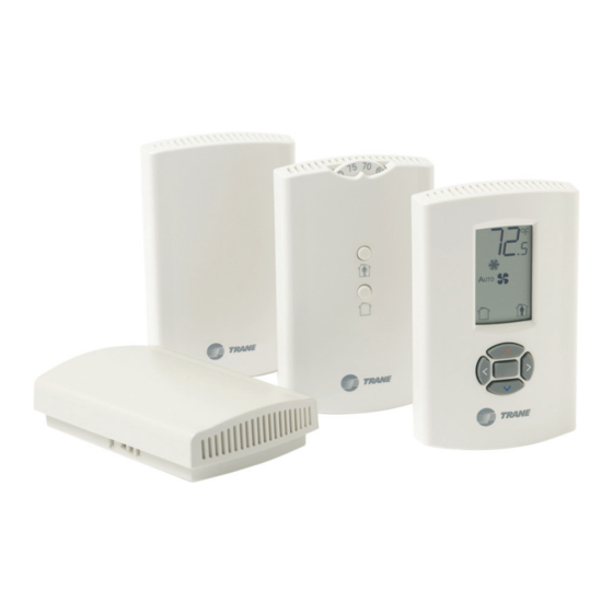
Wireless zone sensors
Hide thumbs
Also See for WTS:
- Installation, operation and maintenance manual (52 pages) ,
- Installation, operation and maintenance manual (37 pages)
Table of Contents
Advertisement
Installation, Operation, and Maintenance
Wireless Zone Sensors
Models WTS, WZS, AND WDS
Only qualified personnel should install and service the equipment. The installation, starting up, and servicing of
heating, ventilating, and air-conditioning equipment can be hazardous and requires specific knowledge and training.
Improperly installed, adjusted or altered equipment by an unqualified person could result in death or serious injury.
When working on the equipment, observe all precautions in the literature and on the tags, stickers, and labels that are
attached to the equipment.
April 2020
SAFETY WARNING
BAS-SVX04G-EN
Advertisement
Table of Contents

Related Manuals for Trane WTS


Summary of Contents for Trane WTS
- Page 1 Installation, Operation, and Maintenance Wireless Zone Sensors Models WTS, WZS, AND WDS SAFETY WARNING Only qualified personnel should install and service the equipment. The installation, starting up, and servicing of heating, ventilating, and air-conditioning equipment can be hazardous and requires specific knowledge and training.
- Page 2 CFCs and HCFCs such as saturated or unsaturated HFCs and HCFCs. Important Responsible Refrigerant Practices Trane believes that responsible refrigerant practices are important to the environment, our customers, and the air conditioning industry. All technicians who handle refrigerants must be certified according to local rules.
- Page 3 Non-Trane personnel should always follow local regulations. Copyright This document and the information in it are the property of Trane, and may not be used or reproduced in whole or in part without written permission. Trane reserves the right to revise this publication at any time, and to make changes to its content without obligation to notify any person of such revision or change.
-
Page 4: Table Of Contents
Table of Contents General Information ..........6 Product Description . - Page 5 Table of Contents Changing Temperature Settings ....... . 32 Changing Heating and Cooling Room Temperature Settings (dual setpoint systems only) .
-
Page 6: General Information
® Trane wireless sensor sets are compatible with any Trane unit controller that uses a standard 10 k temperature input. The sets include sensor, receiver, wiring harness, and two AA lithium batteries. No further software or hardware is necessary for site evaluation, installation, or maintenance. -
Page 7: Part Numbers
General Information Part Numbers The following table lists available models by part number: Part number Description X1379082101 Model WTS sensor only X1379082201 Model WDS sensor only X1379082301 Model WTS sensor set X1379082401 Model WDS sensor set X13790492 Model WZS, sensor only, Fahrenheit... -
Page 8: Dimensions
General Information Dimensions The following illustration provides specific dimension details. The dimensions are the same for all models. TYP R.07 in (R1.8) mm) 0.31 in (8 mm) TYP 0.24 in (6 mm) 2.9 in (73.5 cm) 1.08 in (27.5 mm) 0.12 in (3 mm) 3.39 in (86 mm) 2.48 in (63 mm) -
Page 9: Pre-Installation
Pre-Installation This section provides the following pre-installation information: • Location considerations • Height requirements • Mounting surfaces • Address settings Location Considerations Placement of the sensor and the receiver is critical to proper operation. For most installations, barriers limit proper radio signal strength more than distance. For best radio transmission range and reliability, mount the receiver and sensor in line of sight. -
Page 10: Height Requirements
Pre-Installation Height Requirements The recommended maximum mounting height is 54 inches from the bottom of the back plate to the floor. If a parallel approach by a person in a wheelchair is required, reduce the maximum height to 48 inches. Note: Consult section 4.27.3 of the 2002 ADA (Americans with Disability Act) guideline, and local building codes, for further details regarding wheelchair requirements. - Page 11 Pre-Installation To set the receiver and sensor addresses: 1. Using a small screwdriver, set the three rotary address switches (locations S1, S2, S3) on the receiver to an address between 001 and 999 (see Figure 1). (You do not have to remove the covers to access the rotary address switches.) Note: Do not use 000 as an address.
-
Page 12: Installation
Installation This section provides step-by-step installation instructions. Read through the pre-installation information before proceeding with installation. Important: It is recommended that you install the sensor set in the order presented in this section. Mounting the Receiver Back Plate To mount the receiver back plate: 1. -
Page 13: Wiring The Receiver To The Unit Controller
Installation Wiring the Receiver to the Unit Controller Power requirements and wiring instructions for the receiver are described in this section. Power Requirements The required power for the receiver is 24 Vac or 24 Vdc and less than 1 VA. The receiver is designed to be powered by the host unit controller. - Page 14 Installation Table 1. Wiring harness: Wire identification Wire label Color Function HEATING SET Brown Space temperature heating setpoint (WDS only) FAN SYSTEM Green Fan and system control (WDS only) SETPOINT Space temperature setpoint (WDS and WZS only) ZONE White Zone temperature GND-SIGNAL Black...
- Page 15 Installation Figure 3. Wiring a receiver to a unit controller through the opening in the back of the receiver back plate Figure 4. Wiring a receiver to a unit controller through the bottom slot in receiver cover BAS-SVX04G-EN...
-
Page 16: Replacing The Receiver Cover
Installation Replacing the Receiver Cover To replace the cover: 1. Hook the cover over the top of the back plate. Apply light pressure to the bottom of the cover until it snaps in place. 2. Install the security screw into the bottom of the cover. Security screw Applying Power to the Receiver Restore power to the UCM. -
Page 17: Observing The Receiver For Readiness To Associate
Installation Observing the Receiver for Readiness to Associate After initial power up, the receiver conducts a channel scan for 20 seconds. During this time, the receiver selects from 16 available channels the clearest channel on which to operate. LED1, LED2, and LED3 flash rapidly in succession (round-robin style) while the channel scan is in progress, as shown in part 1 of the illustration. -
Page 18: Associating The Sensor To The Receiver
Installation Associating the Sensor to the Receiver To associate the sensor to the receiver: 1. Remove the sensor cover by firmly pressing the thumb tab at the bottom of the cover and pulling the cover away from the back plate. 2. -
Page 19: Testing Signal Strength And Battery Status
1. Firmly press and release the Test button on the bottom of the sensor (as illustrated below). 2. For models WTS and WZS, view LED1, LED2, and LED3 to determine the signal strength. View LED5 to determine the battery status. (See the illustration for model WTS and WZS sensors.) Note: The LEDs will turn Off after 5 seconds to conserve battery strength. -
Page 20: Mounting The Sensor Back Plate
Installation Mounting the Sensor Back Plate To mount the sensor back plate: 1. Hold the back plate against the mounting surface and mark the screw locations. 2. Secure the back plate against the mounting surface using included hardware. The figure shows an example of mounting the back plate of the sensor into sheetrock or plaster. BAS-SVX04G-EN... -
Page 21: Configuring The Wireless Sensor (Model Wds Only)
Installation Configuring the Wireless Sensor (Model WDS only) The configuration of the sensor determines which system features can be accessed and changes can be made by the tenant (for example, changes to cooling/heating mode, setpoint, or fan speed. Verify system and associated unit features before configuring the sensor. The building owner or operator may choose to limit tenant access to certain features. - Page 22 Installation 2. Press the center button on the keypad to begin the configuration process. Center button 3. Configure the sensor options in the order shown in the table. • Press to scroll to the next selection (as illustrated). • Press to move to the next menu (as illustrated).
- Page 23 Installation Setting Configuration options System (continued) b) Dual setpoint emergency heat/ heat/cool/ emergency heat/ heat/cool/auto/off auto/off heat/cool/off c) No setpoint no system options enabled auto/off auto/off/ auto/off/low auto/high (on) low/high med/high Note: Not all fan options are available for all systems. off/high (on) off/low/high off/low/...
- Page 24 Installation 4. Review the display to ensure that you have selected the correct configuration options. Figure 5. The example shows a display that has been configured for: • Dual setpoint • Temperature units (Fahrenheit) • Temperature resolution to tenths of a degree •...
-
Page 25: Optional Features
Installation Optional Features Displaying Setpoint or Temperature You can configure the sensor to display either the temperature (default) or setpoint. To select either option: 1. Verify that the sensor is in operating mode and at the home screen. 2. Press the up and down arrows for 3 seconds. The arrow indicates setpoint display, as shown in the illustration. -
Page 26: Replacing The Sensor Cover
Installation 3. Press the left and right arrows for 4 seconds. Table 2. Note: If you try to access a feature that is locked, the locked symbol will appear on the display. If you press a keypad button to try change a locked setting, the locked symbol will flash. Replacing the Sensor Cover To replace the cover: 1. -
Page 27: Operation
Operation This section describes sensor operations. Temporary Occupancy (Timed Override) Temporary occupancy (timed override) is available on models WDS and WZS. Temporary occupancy can be selected to adjust temperature, fan, or heat/cool settings after the system has changed to unoccupied mode. System control will revert to unoccupied after a pre-determined time period. -
Page 28: Service Pin Request
Operation Service Pin Request Model WZS and WDS sensors can communicate a service pin request to their corresponding unit controllers using the following methods. Model WZS Sensor To initiate a service pin request, press the Occupied button (Figure 6, p. 27) for 10–25 seconds. -
Page 29: Star(*)/Double Star(**) Function
Operation Star(*)/Double Star(**) Function The star/double star function is available on models WDS and WZS. Consult the appropriate unit controller documentation for information about this function. The WZS sensor set supports star(*) and double star(**) on the sensor thumb wheel (Figure •... -
Page 30: Receiver Power-Up Sequence
(see “Output Values—Failure and Default Modes of Operation” p. 42). Note: Once a receiver communicates to a WTS sensor, the receiver disables (opens) its zone setpoint output indefinitely. BAS-SVX04G-EN... -
Page 31: Sensor Transmission Time And Temperature Variables
– 0.1°F for model WZS sensor – 0.1°C for a model WDS sensor Operating Mode (Model WDS) This section describes the Trane model WDS wireless sensor operation. Figure 9 shows an example of a model WDS that has been configured and is in operating mode. -
Page 32: Changing Temperature Settings
Operation Changing Temperature Settings This symbol shows the current room 1. To increase the room temperature, press temperature, or your temperature setting, while you are making an adjustment. To decrease the room temperature, press When you select a setpoint, this symbol 2. -
Page 33: Requesting Temporary Occupancy
Indicates full Indicates 50% of Replace batteries. battery power battery life left. Flashing symbol Use only UL-listed non-rechargeable 1.5 V indicates that lithium AA batteries (Trane p/n X13770035010 approximately 14 days of or equivalent). operation remain. BAS-SVX04G-EN... -
Page 34: Maintenance And Troubleshooting
LED3 LED5 The sensor for models WTS and WZS have four LEDs: LED1, LED2, LED3, and LED5. The sensor for model WDS has test symbols and error codes that appear on the display. All three sensor models have a Test button. -
Page 35: Diagnostics
Maintenance and Troubleshooting Diagnostics LED1, LED2, and LED3, located on the sensor of models WTS and WZS, respond to diagnostics by exhibiting specific blinking patterns. View their response by pressing the Test button. (See Table Error codes appear on the display of the model WDS sensor when diagnostics occur. (See Table Table 3. -
Page 36: Testing Battery Status
Testing Battery Status Initiate a battery status test as follows: • On models WTS and WZS, push the Test button on the sensor (see location on Figure 11, p. 34). LED5 on the sensor responds by indicating the level of battery strength, as shown in... -
Page 37: 24 V Power Status Indicator
4. Place or hold the sensor at the desired location 5. Press the Test button (S5) on the sensor and observe the signal strength as indicated by LED1, LED2, and LED3 on models WTS and WZS, and on the display on model WDS (Figure 11, p. -
Page 38: Replacing Sensor Batteries
Use two non-rechargeable 1.5 V lithium AA batteries in the sensor. To maintain UL rating, use only UL-listed lithium batteries. The sensor ships with Energizer™ L91 batteries already installed. Replacement batteries are available at Trane Service Parts Centers (p/n X13770035010) or other local suppliers. -
Page 39: Manual Association
Maintenance and Troubleshooting 1. Observe the polarity indicators that are molded into the cover. 2. Install two batteries (of the type specified in “Battery Type,” p. 38) in the battery-holding slot that is molded into the sensor cover. The sensor has been designed to prevent damage if the batteries are installed backwards, to reduce the potential for injury. -
Page 40: Sensor/Receiver Compatibility
No special tools or software are necessary to service and test the wireless sensor system. Test the system by using: • The LEDs on the receiver, LEDs on the model WTS and WZS sensor, and the display on the model WDS sensor •... -
Page 41: Procedure For Testing The Receiver
Maintenance and Troubleshooting • Model WDS: Battery life (“Testing Battery Status,” p. 33) and signal strength (“Testing Signal Strength,” p. 33) are indicated on the display. Procedure for Testing the Receiver If the receiver is not working as expected: 1. Verify that the receiver is powered. 2. -
Page 42: Output Values-Failure And Default Modes Of Operation
Maintenance and Troubleshooting Output Values—Failure and Default Modes of Operation The following table provides output values for failure and default modes of operation, which can be used for troubleshooting. Zone temperature Zone setpoint Heating Fan/System Situation output output setpoint output output 2320 ... - Page 43 Maintenance and Troubleshooting Table 9. Resistance measurements for zone temperature and setpoints Nominal zone temperature Nominal setpoint and heating Zone or setpoint temperature output resistance setpoint output resistance 938 55°F (12.8°C) 17.47 k 792 60°F (15.6°C) 15.3 k 695 ...
-
Page 44: Cleaning The Sensor
Maintenance and Troubleshooting Cleaning the Sensor NOTICE: Equipment Damage! Spraying glass cleaner or any other solution directly on the sensor may damage it. You can clean the sensor by applying glass cleaner to a soft, non-abrasive cloth, and gently wiping the face, including the buttons and LCD display. -
Page 45: Specifications
Specifications The following table provides specifications for all models of the wireless sensor sets. Sensor operating temperature 32 to 122ºF (0 to 50ºC) Receiver operating temperature -40 to 158ºF (-40 to 70ºC) Storage temperature -40 to 185ºF (-40 to 85°C) Storage and operating humidity range 5% to 95%, non-condensing Accuracy... -
Page 46: Appendix A: Wiring Diagrams
Appendix A: Wiring Diagrams Single Transformer Wiring Typically, a single transformer powers the unit controller, which provides power to the receiver. This is the recommended method of wiring. WARNING Risk of Fire and Electrical Shock! To avoid the risk of fire or electrical shock, do not interconnect the multiple class 2 circuits. -
Page 47: Multiple Transformer Wiring
Appendix A: Wiring Diagrams Multiple Transformer Wiring WARNING Shock Hazard! If the use of multiple transformers is necessary, locate them so that they do not allow simultaneous human contact. Touching both 24 Vac outputs simultaneously on two electrically connected transformers could result in death or serious injury. Using a dedicated transformer to power the receiver is seldom necessary and is not advised. -
Page 48: Appendix B: Agency Compliance
Appendix B: Agency Compliance The following table presents agency compliance information for wireless sensor set models as shown. United States compliance UL listed:UL 94-5VA Flammability rating (all models) UL 916: Energy management equipment FCC CFR47, Section 15.247 & Subpart E Digital Modulation Transmission with no SAR (FCC Identification TFB-FREESTAR) This device complies with Part 15 of the FCC Rules. - Page 52 For more information, please visit trane.com or tranetechnologies.com. Trane has a policy of continuous product and product data improvement and reserves the right to change design and specifications without notice. We are committed to using environmentally conscious print practices.
Need help?
Do you have a question about the WTS and is the answer not in the manual?
Questions and answers