
Related Manuals for HP V1905 Series


Summary of Contents for HP V1905 Series
-
Page 1: Getting Started Guide
HP V1905 Switch Series Getting Started Guide *5998-2235* Part number: 5998-2235 Document version: 2... - Page 2 The only warranties for HP products and services are set forth in the express warranty statements accompanying such products and services. Nothing herein should be construed as constituting an additional warranty.
-
Page 3: Table Of Contents
Contents Getting Started ····························································································································································· 1 Introducing the Switch ························································································································································· 1 Overview of the Switch ················································································································································· 1 Summary of Hardware Features ·································································································································· 1 Front View Detail ··························································································································································· 2 LED Status Indicators······················································································································································ 3 System Specifications ···················································································································································· 4 ... - Page 4 Viewing VLAN Details ················································································································································ 39 Viewing VLAN Port Details ········································································································································ 40 Aggregating Port ······························································································································································ 41 Overview ····································································································································································· 41 LACP ············································································································································································· 41 Link Aggregation Types ·············································································································································· 41 Configuring Link Aggregation ··································································································································· 42 Configuring LACP ······················································································································································· 45 ...
- Page 5 ········································································································································································ 121 save ············································································································································································ 122 tftp update ································································································································································· 122 Support and other resources ·································································································································· 123 Contacting HP ································································································································································· 123 Related information ························································································································································· 123 Conventions ····································································································································································· 123 Subscription service ························································································································································ 124 Glossary ··································································································································································· 125 ...
-
Page 6: Getting Started
V1905-24-PoE Switch JD992A, which are referred to as the Switch. This manual uses the Web interfaces of the HP V1905-24-PoE Switch JD992A in the example text. This chapter contains introductory information about the installation of the Switch and how the Switch can be used in your network. -
Page 7: Front View Detail
Front View Detail Figure 46 shows the front panel of the HP V1905-24 Switch JD990A 26-Port unit. Figure 46 HP V1905-24 Switch JD990A 26-Port—front panel. Figure 47 shows the front panel of the HP V1905-24-PoE Switch JD992A 26-Port unit. -
Page 8: Led Status Indicators
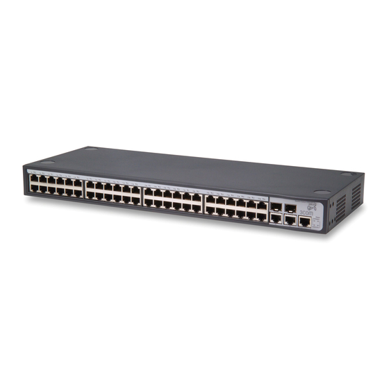
Figure 47 HP V1905-24-PoE Switch JD992A 26-Port—front panel. Figure 48 shows the front panel of the HP V1905-48 Switch JD994A 50-Port unit. Figure 48 HP V1905-48 Switch JD994A 50-Port—front panel. LED Status Indicators The Switch provides LED indicators on the front panel to monitor the switch. -
Page 9: System Specifications
The SFP module is not inserted or is not recognized. Green The port is supplying power to the device connected to it. PoE Power (Only supported by HP The port is not supply power to the device connected to it V1905-24-PoE Switch JD992A) or not connected. -
Page 10: Installing The Switch
Water or moisture cannot enter the case of the unit. Air flow around the unit and through the vents on the side of the case is not restricted (HP recommends that you provide a minimum of 25 mm (1 in.) clearance). -
Page 11: Rack-Mounting Or Free-Standing
Rack-Mounting or Free-Standing The unit can be mounted in a 19-inch equipment rack using the mounting kit or it can be free standing. Do not place objects on top of the unit or stack. CAUTION: If installing the switch in a free-standing stack of different size Baseline or Super stack 3 units, the smaller units must be installed above the larger ones. -
Page 12: Supplying Power To The Switch
Power problems can be the cause of serious failures and downtime in your network. Ensure that the power input to your system is clean and free from sags and surges to avoid unforeseen network outages. HP recommends that you install power conditioning, especially in areas prone to blackout, power dips and electrical storms. -
Page 13: Checking For Correct Operation
Resetting the switch to its factory default erases all your settings. You will need to reconfigure the switch after you reset it. If these do not resolve the issue, please contact your HP network supplier for assistance. Using SFP Transceivers The following sections describe how to insert an SFP transceiver into an SFP slot. - Page 14 Use this transceiver to connect the switch directly to a single mode fiber-optic cable or to multi-mode fiber using a conditioned launch cable. To activate the SFP port: Hold the transceiver so that the fiber connector is toward you and the product label is visible, as shown Figure 51.Ensure the wire release lever is closed (in the upright position).
-
Page 15: Performing Spot Checks
At frequent intervals, you should visually check the switch. Regular checks can give you an early warning of a possible failure; any problems can then be attended to when there will be least effect on users. HP recommends periodically checking the items listed in Table... - Page 16 NOTE: For most installations, HP recommends that you configure the switch IP information manually. This makes management simpler and more reliable as it is not dependent on a DHCP server, and eliminates the risk of the IP address changing. You can use ip address command to configure the static IP for your switch through the Console Port (see “CLI...
-
Page 17: Connecting To The Web Interface
Connecting To the Web Interface The switch has a built-in Web interface that you can use to set the user password, change the IP address that is assigned to the switch, and configure its advanced settings. This chapter introduces the setting the menu items and buttons that are available on the Web interface. The following topics are covered: Requirements for Accessing the Web Interface ... -
Page 18: Logging On To The Web Interface
Table 43 Default User and Password User Name Default Password Access Level Management: The user can access and change all admin manageable parameters Logging On to the Web Interface To log on to the Web interface, do the following: Open your Web browser and enter the IP address of the switch that you wish to manage in the address bar (For example, in the following format: http://xxx.xxx.xxx.xxx). - Page 19 Figure 53 Switch Screen Layout Table 44 Available Menu Items Menu Item Description Contains tabs that allow you to: Provide a summary of the switch’s basic settings and versions of Device Summary current components. Display the description for each color coded port. Save Configuration Saves the switch’s configuration Allows you to setup, modify, or view the IP configuration...
- Page 20 Menu Item Description Contains tabs that allow you to: Create a VLAN. Modify a VLAN. Modify VLAN membership for a port. VLAN Rename a VLAN. Remove a VLAN. Display VLAN membership for a port. ...
-
Page 21: Buttons
Cable Diagnostics Display selected cable diagnostics information for all ports. Display all cable diagnostics information for a single port. Displays HP contact information and describes how to use the online Help help system. Logout Allows you to securely log off the Web interface. - Page 22 Select All: Allows the user to select all ports. Select None: Removes the ports selected. Help: Click to display the context-sensitive help information for the screen that is currently displayed. The help pages provide information on the tasks that you can perform on each screen.
-
Page 23: Configuring The Switch
Viewing System Access Settings CAUTION: To ensure that unauthorized users do not access the Web interface, HP recommends that you set an admin password when you first configure the switch. Defining System Access The System Access Setup Page allows network administrators to define users, passwords, and access levels for users using the System Access Interface. -
Page 24: Modifying System Access
The System Access Setup Page contains the following fields: Table 45 System Access Setup Page item description Item Description User Name Defines the user name. The default value is admin. Defines the user access level. The lowest user access level is Monitor and the highest is Management. -
Page 25: Removing System Access
Removing System Access The System Access Remove Page allows network administrators to remove users from the System Access Interface. CAUTION: The last user with management access may not be deleted. Click Administration System Access Remove. The System Access Remove Page opens. Figure 56 System Access Remove Page Viewing System Access Settings The System Access Summary Page displays the current users and access levels defined on the switch. -
Page 26: Configuring Ip And Mac Address Information
Configuring IP and MAC Address Information This section contains information for defining IP interfaces, and includes the following sections: Defining IP Address Configuring ARP Settings Configuring MAC Address Table Defining IP Address To enable the other devices on the network to communicate with the switch, you need to assign an IP address to it: either by DHCP or by assigning a static IP address. - Page 27 Removing ARP Entries Viewing ARP Settings Defining ARP Settings The ARP Settings Setup Page allows network managers to define ARP parameters for specific interfaces. Click Administration ARP Settings Setup. The ARP Settings Setup Page opens. Figure 59 ARP Settings Setup Page The ARP Settings Setup Page contains the following fields: Table 49 ARP Settings Setup Page item description Item...
- Page 28 Figure 60 ARP Entries Remove Page The ARP Entries Remove Page contains the following fields: Table 50 ARP Entries Remove Page item description Item Description Specifies the types of ARP entries that are cleared. The possible values are: None: Maintains the ARP entries. ...
-
Page 29: Configuring Mac Address Table
Figure 61 ARP Settings Summary Page The ARP Settings Summary Page contains the following fields: Table 51 ARP Settings Summary Page item description Item Description Interface Indicates the VLAN for which ARP parameters are defined. IP Address Indicates the IP address, which is associated with the MAC Address. Displays the station MAC address, which is associated in the ARP table with the IP MAC Address address. - Page 30 Adding MAC Addresses to the Address Table The Address Table Add Page allows the network manager to assign MAC addresses to ports with VLANs. Click Monitoring Address Table Add. The Address Table Add Page opens. Figure 62 Address Table Add Page The Address Table Add Page contains the following fields: Table 52 Address Table Add Page item description Item...
- Page 31 Removing MAC Addresses for the specific port The Port Remove Page allows the network manager to remove MAC Addresses for the specific port from the Address Table. Click Monitoring Address Table Port Remove. The Port Remove Page opens. Figure 64 Port Remove Page Select a port to remove MAC Addresses.
- Page 32 Figure 66 Address Table Summary Page The Address Table Summary Page contains the following fields: Table 53 Address Table Summary Page item description Item Description Filters the list of MAC addresses displayed according to the type of MAC address configuration. Possible values are: ...
-
Page 33: Configuring Port
Figure 67 Port Summary Page The Port Summary Page contains the following fields: Table 54 Port Summary Page item description Item Description Filters the list of MAC addresses displayed according to the type of MAC address configuration. Possible values are: ... - Page 34 Defining Port Settings Viewing Port Settings Viewing Port Details Defining Port Settings The Port Setup Page allows network managers to configure port parameters for specific ports. Click Port Administration Setup. The Port Setup Page opens. Figure 68 Port Setup Page The Port Setup Page contains the following fields: Table 55 Port Setup Page item description...
- Page 35 Item Description Auto: Use to automatically configure the port. Full: The interface supports transmission between the switch and its link partner in both directions simultaneously. Half: The interface supports transmission between the switch and its link partner in only one direction at a time.
-
Page 36: Configuring Poe
Item Description Displays the flow control status on the port. The possible field values are: Flow Control Enabled: Enables flow control on the port. Disabled: Disables flow control on the port. Displays the configured rate for the port. The port type determines what speed setting options are available. -
Page 37: Part Number
Defining Port PoE Viewing PoE Defining Port PoE The Port PoE Setup Page allows the network manager to configure port PoE settings. Click Port PoE Setup. The Port PoE Setup Page opens. Figure 71 Port PoE Setup Page The Port PoE Setup Page contains the following fields: Table 57 Port PoE Setup Page item description Item... - Page 38 Item Description Selected Ports Displays the PoE configuration for the selected ports. Viewing PoE The Port PoE Summary Page displays the switch and port PoE settings. Click Port PoE. The PoE Summary Page opens. Figure 72 Port PoE Summary Page The Port PoE Summary Page contains the following fields: Table 58 Port PoE Summary Page item description Item...
-
Page 39: Viewing Port Statistics
Item Description Guarantee: Power is guaranteed to the selected port, provided that the power is available. This setting overrides the priority assigned to lower port numbers by the auto mode. Power Indicates the maximum amount of power available to the interface. The field value Max(watts) is displayed in Watts. -
Page 40: Configuring Vlan
Item Description Broadcast Packets Displays the number of good broadcast packets received on the interface since the Received switch was last refreshed. This number does not include Multicast packets. Multicast Packets Displays the number of good Multicast packets received on the interface since the Received switch was last refreshed. -
Page 41: Creating Vlans
VLANs function at Layer 2. Since VLANs isolate traffic within the VLAN, a Layer 3 router working at a protocol level is required to allow traffic flow between VLANs. Layer 3 routers identify segments and coordinate with VLANs. Broadcast and Multicast traffic is transmitted only in the VLAN in which the traffic is generated. -
Page 42: Modifying Vlan
Modifying VLAN The Modify VLAN Page allows the network manager to change VLAN membership. CAUTION: At least one port must always be an untagged member of VLAN 1 (the management VLAN). If you choose to connect all ports to VLANs other than VLAN 1, you will no longer be able to access the Web interface. If this happens, you will need to reset the switch to factory settings. -
Page 43: Modifying Port Vlan Settings
Modifying Port VLAN Settings The Modify Port VLAN Page allows the network manager to modify port VLAN settings. Click Device VLAN Modify Port. The Modify Port VLAN Page opens. Figure 76 Modify Port VLAN Page The Modify Port VLAN Page contains the following fields: Table 62 Modify Port VLAN Page item description Item Description... -
Page 44: Removing Vlans
Removing VLANs The VLAN Remove Page allows the network administrator to remove VLANs. Click Device VLAN Remove. The VLAN Remove Page opens. Figure 78 VLAN Remove Page Viewing VLAN Details The VLAN Detail Page provides information and global parameters on the VLANs configured on the system. Click Device ... -
Page 45: Viewing Vlan Port Details
Table 63 VLAN Detail Page item description Item Description Select a VLAN to Selects a VLAN to be display its settings Display Displays the membership type for each VLAN. The possible field values are: Untagged: Indicates the interface is an untagged member of the VLAN. ... -
Page 46: Aggregating Port
Aggregating Port Overview Link aggregation aggregates multiple physical Ethernet ports into one logical link, called a Link Aggregation Group (LAG). It allows you to increase bandwidth by distributing traffic across the member ports in the aggregation group. In addition, it provides reliable connectivity because these member ports can dynamically back up each other. -
Page 47: Configuring Link Aggregation
Among the selected ports in an aggregation group, the one with smallest port number operates as the master port. Other selected ports are the member ports. Static LACP Aggregation A static LACP aggregation group is also manually created. All its member ports are manually added and can be manually removed (this prevents the system from automatically adding or removing ports from the group). - Page 48 Figure 81 Link Aggregation Create Page The Link Aggregation Create Page includes the following fields: Table 65 Link Aggregation Create Page item description Item Description Enter Aggregation Defines the group ID Group ID Manual Defines Manual Aggregation Static Defines Static LACP Aggregation To create a new link aggregation group: Enter a LAG ID in the box field.
- Page 49 Figure 82 Link Aggregation Modify Page Removing Link Aggregation The Link Aggregation Remove Page allows the network manager to remove group IDs containing member ports. Click Port Link Aggregation Remove. The Link Aggregation Remove Page opens. Figure 83 Link Aggregation Remove Page Viewing Link Aggregation The Link Aggregation Summary Page displays the state of the current link aggregation.
-
Page 50: Configuring Lacp
The Link Aggregation Summary Page includes the following fields: Table 66 Link Aggregation Summary Page item description Item Description Group ID Displays the Link Aggregated Group ID. The field range is 1-6. Displays the type of link aggregation for the Group ID. The possible field value is Type Static or LACP. -
Page 51: Configuring Stp
Click Port Link Aggregation LACP. The LACP Summary Page opens. Figure 86 LACP Summary Page The LACP Summary Page contains the following fields: Table 68 LACP Summary Page item description Item Description Port-Priority Displays the LACP priority value for the port. Displays the administrative LACP timeout. - Page 52 After all the bridges on the network have determined the configuration of their ports, each bridge only forwards traffic between the Root Port and the ports that are the Designated Bridge Ports for each network segment. All other ports are blocked, which means that they are prevented from forwarding traffic. The device supports the following STP versions: Classic STP: Provides a single path between end stations, avoiding and eliminating loops.
- Page 53 Table 69 STP Global Setup Page item description Item Description Defines whether STP is enabled on the switch. The possible field values are: Spanning Tree Disable: Disables STP and RSTP on the switch. State Classic: Enables STP on the switch. ...
- Page 54 Item Description hours 10 minutes and 4 seconds. Modifying STP Interface Parameters The STP Interface Parameters Modify Page allows network managers to modify STP parameters to specific interfaces. Click Device Spanning Tree Modify. The STP Interface Parameters Modify Page opens. Figure 88 STP Interface Parameters Modify Page The STP Interface Parameters Modify Page contains the following fields: Table 70 STP Interface Parameters Modify Page item description...
- Page 55 Item Description Enabled: Enables the default path cost on the port. This is the default value. Disabled: Disables the default path cost on the port. Defines the port contribution to the root path cost. When Default Path Cost is disabled, you can configure it;...
- Page 56 Item Description Indicates if Fast Link is enabled on the port. If Fast Link mode is enabled for a port, the port is automatically placed in the Forwarding state when the port link is up. Fast Link Port Fast optimizes the STP protocol convergence. STP convergence takes 30 seconds and is not dependent on the number of switches in the network.
-
Page 57: Configuring Igmp Snooping
Item Description Indicates the cost of the port participating in the STP topology. Ports with a lower cost Designated Cost are less likely to be blocked if STP detects loops. Indicates the number of times the port has changed from Forwarding state to Blocking Forward Transitions state. -
Page 58: Configuring Acl
Table 72 IGMP Snooping Setup Page item description Item Description Defines whether IGMP Snooping is enabled on the switch. The possible field values are: IGMP Snooping Status Enabled: Indicates that IGMP Snooping is enabled on the switch. Disabled: Indicates that IGMP Snooping is disabled on the switch. This is the default value. - Page 59 Figure 91 MAC Based ACL Setup Page The MAC Based ACL Setup Page contains the following fields: Table 73 MAC Based ACL Setup Page item description Item Description Selection ACL Selects an existing MAC-based ACL to which rules are to be added. Defines a new user-defined MAC-based Access Control List.
- Page 60 Item Description VLAN ID Matches the packet's VLAN ID to the rule. The possible field values are 1 to 4094. Classifies traffic based on the CoS tag value. CoS Mask Defines the CoS mask used to classify network traffic. Ethertype Provides an identifier that differentiates between various types of protocols.
- Page 61 Click Apply. Removing MAC Based ACL The MAC Based ACL Remove Page allows the network administrator to remove MAC-based ACL or MAC-based ACL rules. Click Device ACL MAC Based ACL Remove. The MAC Based ACL Remove Page opens. Figure 93 MAC Based ACL Remove Page The MAC Based ACL Remove Page contains the following fields: Table 74 MAC Based ACL Remove Page item description...
-
Page 62: Configuring Ip Based Acl
Figure 94 MAC Based ACL Summary Page The MAC Based ACL Summary Page contains the following fields: Table 75 MAC Based ACL Summary Page item description Item Description ACL Name Contains a list of the MAC-based ACL. ACL Priority Indicates the ACL Priority. Indicates the rule priority, which determines which rule is matched to a packet on a Priority first match basis. - Page 63 Click Device ACL IP Based ACL Setup. The IP Based ACL Setup Page opens. Figure 95 IP Based ACL Setup Page The IP Based ACL Setup Page contains the following fields: Table 76 IP Based ACL Setup Page item description Item Description Selection ACL...
- Page 64 Item Description connection. Fin: Finish. This indicates there is no more data from the sender. This marks a normal closing of the session between the sender and receiver. If selected, enables matching the source port IP address to which packets are addressed Source IP Address to the rule, according to a wildcard mask.
- Page 65 Figure 96 IP Based ACL Modify Page NOTE: The description of parameters in the page refers to Defining IP Based ACL. Selects the ACL to be modified. Selects the Rule to be modified. Modifies the fields of the Rule. Click Apply. Removing IP Based ACL The IP Based ACL Remove Page allows the network administrator to remove IP-based ACL or IP-based ACL rules.
- Page 66 To remove IP-based ACL rules: Select an ACL Name. For each rule to be removed, check the box to the left of the row in the rules table. To remove all rules, the topmost box may be checked. Click Remove. Viewing IP Based ACL The IP Based ACL Summary Page displays information regarding IP-based ACL configured on the switch.
-
Page 67: Configuring Acl Binding
Item Description Indicates the ACL forwarding action. In addition, the port can be shut down, a trap Action can be sent to the network administrator, or packet is assigned rate limiting restrictions for forwarding. Configuring ACL Binding This section includes the following topics: ... - Page 68 Figure 100 ACL Binding Remove Page The ACL Binding Remove Page contains the following fields: Table 80 ACL Binding Remove Page item description Item Description Remove All Port Remove all the port binding according to the current ACL. Binding By ACL ACL Name Displays the name of ACL to be removed from the selected port.
-
Page 69: Configuring Qos
Table 81 ACL Binding Summary Page item description Item Description MAC-based ACL Displays the MAC based ACL to which the interface is assigned. IP-based ACL Displays the IP based ACL to which the interface is assigned Configuring QoS Quality of Service (QoS) provides the ability to implement QoS and priority queuing within a network. For example, certain types of traffic that require minimal delay, such as Voice, Video, and real-time traffic can be assigned a high priority queue, while other traffic can be assigned a lower priority queue. -
Page 70: Configuring Queue Algorithm
Table 82 CoS Setup Page item description Item Description Specifies if QoS is enabled on the switch. The possible values are: Disabled: Restores the switch factory defaults for QoS values and disables QoS Mode configure QoS values on the switch. ... -
Page 71: Configuring Cos To Queue
Figure 104 Queue Setup Page The Queue Setup Page contains the following fields: Table 84 Queue Setup Page item description Item Description This highest queue is transmitted first if any packets are in the highest queue. When HQ-WRR the highest queue is exhausted, the remaining queues are served by WRR. This queue algorithm specifies which port queue that each packet should be sent to. -
Page 72: Configuring Dscp To Queue
Table 85 CoS to Queue Setup Page item description Item Description Restore Defaults Restores the switch factory defaults for mapping CoS values to forwarding queues. Class of Service Specifies the CoS priority tag values, where 0 is the lowest and 7 is the highest. Queue Defines the traffic forwarding queue to which the CoS priority is mapped. - Page 73 Figure 107 DSCP to Queue Setup Page The DSCP to Queue Setup Page contains the following fields: Table 87 DSCP to Queue Setup Page item description Item Description Restores the switch factory defaults for mapping DSCP values to a traffic forwarding Restore Defaults queue.
-
Page 74: Configuring Trust Mode
Table 88 DSCP to Queue Summary Page item description Item Description DSCP Displays the incoming packet’s DSCP value. Indicates the CoS value forwarding queue to which the DSCP priority is mapped. The possible field values are 0-7. Configuring Trust Mode The Trust Setup Page contains information for configuring trust mode on the switch. - Page 75 Figure 110 Bandwidth Setup Page The Bandwidth Setup Page contains the following fields: Table 90 Bandwidth Setup Page item description Item Description Enable Ingress Rate Enables setting an Ingress Rate Limit. Limit Ingress Rate Limit Defines the ingress traffic limit for the port. The field range of normal port is 3500 Ingress Rate - 100,000 kbits per second, and the field range of combo port is 3500 - Limit...
-
Page 76: Configuring Voice Vlan
IP traffic is received unevenly. The system supports one Voice VLAN. NOTE: The HP V1905-48 Switch JD994A does not support improving the priority of voice streams. There are two operational modes for IP Phones: IP phones are configured with VLAN-mode as enabled, ensuring that tagged packets are used for all ... - Page 77 If the IP phone’s VLAN-mode is disabled, the phone uses untagged packets. The phone uses untagged packets while retrieving the initial IP address through DHCP. The phone eventually uses the Voice VLAN and starts sending tagged packets. This section contains the following topics: Modifying OUI Definitions ...
- Page 78 The Voice VLAN Setup Page provides information for enabling and defining Voice VLAN globally on the switch. Click Device QoS VoIP Traffic Setting Setup. The Voice VLAN Setup Page opens. Figure 113 Voice VLAN Setup Page The Voice VLAN Setup Page contains the following fields: Table 93 Voice VLAN Setup Page item description Item Description...
- Page 79 Table 94 Voice VLAN Port Setup Page item description Item Description Specifies the Voice VLAN mode. The possible field values are: No Changes: Maintains the current Voice VLAN port settings. None: Indicates that the selected port will not be added to a Voice VLAN. This is the default value.
- Page 80 Figure 116 Voice VLAN OUI Summary Page Viewing Voice VLAN The Voice VLAN Summary Page contains information about the Voice VLAN currently enabled on the switch, including the ports enabled and included in the Voice VLAN. Click Device QoS VoIP Traffic Setting. The Voice VLAN Summary Page opens. Figure 117 QoS VoIP Summary Page The Voice VLAN Summary Page contains the following fields: Table 95 Voice VLAN Summary Page item description...
-
Page 81: Configuring Snmp
Configuring SNMP Simple Network Management Protocol (SNMP) provides a method for managing network devices. The switch supports the following SNMP versions: SNMP version 1 SNMP version 2c The SNMP agents maintain a list of variables, which are used to manage the switch. The variables are defined in the Management Information Base (MIB). -
Page 82: Removing Snmp Communities
Table 96 SNMP Communities Setup Page item description Item Description Specifies if SNMP is enabled on the switch. The possible field values are: SNMP Status Enabled: Enables SNMP on the switch. Disabled: Disables SNMP on the switch. Insert New Community Enables adding an SNMP community. -
Page 83: Removing Snmp Traps
Figure 120 SNMP Traps Setup Page The SNMP Traps Setup Page contains the following fields: Table 97 SNMP Traps Setup Page item description Item Description Recipients IP Address Defines the IP address to which the traps are sent. Community String Defines the community string of the trap manager. -
Page 84: Configuring Lldp
Configuring LLDP LLDP Overview The Link Layer Discovery Protocol (LLDP) operates on the data link layer. With LLDP, a device can store and maintain information about itself and the directly-connected neighbor devices for network administrators to check link status. LLDP Operating Mode LLDP can operate in one of the following modes: TxRx: A port in this mode sends and receives LLDPDUs. -
Page 85: Configuring Port-Level Lldp Parameters
Table 98 Global LLDP Parameter Page item description Item Description Enable/disable LACP globally. Two options are available: Enabled: Enables LLDP globally. LLDP Disabled: Disables LLDP globally. By default, LLDP is disabled globally. Set the interval for sending LLDPDUs. A port operating in TxRx mode or Tx mode sends LLDPDUs to its directly connected Transmit Interval device periodically. - Page 86 Figure 123 Port-Level LLDP Parameters Page The Port-Level LLDP Parameters Page contains the following fields:...
- Page 87 Table 99 Port-Level LLDP Parameters Page item description Item Description Enable/disable LLDP on a port. Two options are available: Enabled: Enables LLDP on the port. LLDP Disabled: Disables LLDP on the port. By default, LLDP is enabled on a port. Set the LLDP operating mode.
-
Page 88: Viewing Lldp Information
Item Description basic TLVs will be sent within LLDPDUs. The IEEE 802.1 defined LLDP TLVs supported by the device include the following: Port Vlan ID: Checked to include the VLAN ID(s) on the port. Protocol Vlan ID: Checked to include the IDs of the protocol IEEE 802.1 VLAN(s) on the port. - Page 89 Figure 124 Global LLDP Information and Received LLDP Information Page The Global LLDP Information and Received LLDP Information Page contains the following fields: Table 100 Global LLDP Information and Received LLDP Information Page item description Item Description Added Neighbor Total number of discovered neighbors Deleted Neighbor Total number of deleted neighbors Discarded LLDP's Packet...
-
Page 90: Managing Switch Security
Viewing Port-Level LLDP Information Click Device LLDP Port Summary. The Port-Level LLDP Information Page opens. Figure 125 Port-Level LLDP Information Page Select a port, and then the LLDP information of the port will be displayed in the Summary box. The displayed information includes LLDP status and statistics of the port and the status of the TLVs sent by the port. - Page 91 Uncontrolled Access: Permits uncontrolled communication regardless of the port state. This section includes the following topics: Defining 802.1X Authentication Viewing 802.1X Authentication Defining 802.1X Authentication The 802.1X Setup Page contains information for configuring 802.1X global settings on the switch and defining specific 802.1X setting for each port individually.
- Page 92 Item Description Specifies the admin port authorization state. The possible field values are: Auto: Enables port based authentication on the switch. The interface moves between an authorized or unauthorized state based on the authentication exchange between the switch and the client. ...
- Page 93 Figure 127 802.1X Summary Page The 802.1X Summary Page contains the following fields: Table 102 802.1X Summary Page item description Item Description Current Port Control Displays the current port authorization state. Indicates whether an unauthorized port is allowed to join the Guest VLAN. The possible field values are: Guest VLAN ...
-
Page 94: Defining Radius Client
Defining Radius Client Remote Authentication Dial-in User Service (Radius) is a logon authentication protocol that uses software running on a central server to control access to Radius-aware devices on the network. An authentication server contains a database of multiple user name/password pairs with associated privilege levels for each user or group that require management access to a switch. - Page 95 Configuring LDB Parameters On this page, you can enable or disable the LDB feature and configure the global LDB parameters. Click Security LDB Setup. The LDB Setup Page opens. Figure 129 Configure LDB parameters Table 104 LDB parameter description Item Description Enable/disable port-based authentication globally.
- Page 96 Item Description NOTE: If there is no traffic of authenticated users through a port within the aging time, the port will be aged out and enters the Block state. Enable/disable the LDB feature on a port. Disabled by default Configuring an Authentication Server On this page, you can configure different authentication servers for different VLANs.
-
Page 97: Displaying Ldb
Figure 132 Configure a user account To add a user account, click Add. To modify the password of a user, select the user, enter a new password in the Password text box, and click Modify. Displaying LDB On this page, you can view the LDB mode, state and user passing authentication on each port. Select Security ... -
Page 98: Configuring Broadcast Storm Control
Item Description NORMAL: The user on the port passed the authentication. BLOCK: The port is in the initial state after the LDB feature is enabled or the port is aged out. SLEEP: The number of the user’s authentication attempts exceeded the preset maximum value. -
Page 99: Managing System Information
Table 106 Broadcast Storm Setup Page item description Item Description Defines whether forwarding broadcast packet type is enabled on the interface. The possible field values are: Disabled: Disables broadcast control on the selected port. This is the default. Broadcast Mode ... -
Page 100: Viewing Basic Settings
System Contact Defines the name of the contact person. Product 3C Number Displays the HP switch 3C number MAC Address Displays the switch MAC address. Displays the amount of time since the most recent switch reset. The system time is System Up Time displayed in the following format: Weeks, Days, Hours, Minutes, and Seconds. -
Page 101: Configuring System Name
Item Description Hardware Version Displays the current hardware version of the switch. Enables polling the ports for port information including speed, utilization and port Poll Now status. Viewing Color Keys The Color Key Page provides information regarding the RJ45 or SFP port status on the switch. The various colors key indicate the port status, speed and link of a selected port. -
Page 102: Configuring System Time
Figure 138 System Name Page The System Name Page includes the following fields: Table 110 System Name Page item description Item Description System Name Defines the user-defined switch name. The field length is 0-30 characters Defines the location where the system is currently running. The field length is 0-80 System Location characters. - Page 103 Figure 139 System Time Setup Page The System Time Setup Page contains the following fields: Table 111 System Time Setup Page item description Item Description Current Time Displays the current time in Mon-Day-Year Hour:Min:Sec. Time zone Local Time zone from GMT in which switch is operating. Configure Daylight When day light saving is enabled, one hour will be added to time zone offset Saving Time Manually...
-
Page 104: Save Configuration
Save Configuration Configuration changes are only saved to the switch once the user saves the changes to the flash memory. The Save Configuration tab allows the latest configuration to be saved to the flash memory. Click Save Configuration. The Save Configuration Page opens. Figure 140 Save Configuration Page Click OK. - Page 105 Startup Configuration File: Contains the commands required to reconfigure the switch to the same settings as when the switch is powered down or rebooted. The Startup Configuration file is created by copying the configuration commands from the running configuration file or by downloading the configuration file via TFTP or HTTP.
- Page 106 Restoring Files The Restore Page restores configuration settings that you previously saved to the TFTP or HTTP server. Click Administration Backup & Restore Restore. The Restore Files Page opens. Figure 143 Restore Files Page The Restore Files Page contains the following fields: Table 113 Restore Files Page item description Item Description...
-
Page 107: Managing System Logs
Table 114 Restore Image Page item description Item Description Download via TFTP Enables to download files via TFTP. Download via HTTP Enables to download files via HTTP. Specifies the TFTP Server IP Address from which the image files are TFTP Server IP Address downloaded. -
Page 108: Configuring Logging
Table 116 System Log Severity Levels Severity Level Message Emergency Highest (0) The system is not functioning. Alert The system needs immediate attention. Critical The system is in a critical state. Error A system error has occurred. Warning A system warning has occurred. The system is functioning properly, but a system notice has Notice occurred. -
Page 109: Viewing Logs
Table 117 Logging Setup Page item description Item Description Specifies if device local logs for Cache and servers are enabled. Console logs are enabled by default. Severity level: Specifies the minimum severity level for which a message will be logged. When a severity level is selected, all severity level choices above the selection are selected automatically. -
Page 110: Managing Switch Diagnostics
Table 118 Logging Display Page item description Item Description Save Preview Saves the displayed Log table to a Web (html) page. Clear Logs Clears all logs Log Time Displays the time at which the log was generated. Severity Displays the log severity. Description Displays the log message text. -
Page 111: Configuring Cable Diagnostics
Table 119 Port Mirroring Setup Page item description Item Description Defines the monitor port (destination port) or mirror port (source port). The possible values are: Monitor: Defines the port as the monitor port. Select port type Mirror: Defines the port as the mirrored port to be monitored and indicates the traffic direction to be monitored. - Page 112 Figure 150 Cable Diagnostic Page Select a port to be tested. Step1 Click Apply. The test results of the port are displayed in the textbox. Step2 Viewing Cable Diagnostics The Cable Diagnostics Summary Page displays information on Test Result, Cable Fault Distance, or Last Update for every port on the switch.
-
Page 113: Troubleshooting
Troubleshooting This chapter lists some issues that you may encounter while installing, using, and managing the switch, with suggested courses of corrective action to take. If you encounter an issue that is not listed here and you cannot solve it, please contact your local technical support representative. -
Page 114: Forgotten Static Ip Address
The correct category of cable is being used for the required link speed. Category 3 cables can be used for 10BASE-T operation only. Category 5 cable is required for 100BASE-TX or 1000BASE-T. HP recommends Category 5e or 6 cables for 1000BASE-T operation. - Page 115 Refer to the documentation that accompanies the switch for information on disabling the broadcast operation. If the problem persists and the unit still does not operate successfully, contact your HP network supplier with the following information before returning the unit: Product number and serial number (printed on a label supplied with the unit).
-
Page 116: Cli Reference Guide
CLI Reference Guide This chapter describes using the Command Line Interface (CLI) to manage the switch. The switch is managed through the CLI from a direct connection to the switch console port. Getting Started with the Command Line Interface Using the CLI, network managers enter configuration commands and parameters to configure the switch. Prerequisites ... -
Page 117: Cli Features
Figure 152 Connecting a Workstation to the switch using the Console Port Open your terminal emulation software and configure the COM port settings to which you have connected the cable. The settings must be set to match the default settings for the switch, which are: ... -
Page 118: Command History
Complete online help Enter a “?” character in any view on your terminal to display all the commands available in the view and their brief descriptions. The following takes user view as an example. <Command-Line> ? display Display current system information IP configuration commands in an interface localuser Configure WEB user manager... -
Page 119: Error Messages
Table 121 Access history commands Operation Operation Description Access the previous This operation recalls the previous Press the up-arrow key or <Ctrl+P> history command history command (if available). Access the next history Pressing the down-arrow key or This operation recalls the next history command <Ctrl+N>... -
Page 120: Cli Configuration
Press… To… to the left. The left arrow key or Move the cursor one character to the left. <Ctrl+B> The right arrow key or Move the cursor one character to the right. <Ctrl+F> The up arrow key or <Ctrl+P> Access history commands. The down arrow key or <Ctrl+N>... -
Page 121: Display Management-Vlan
display management-vlan Syntax display management-vlan View User view Parameter None Description Use the display management-vlan command to display the information of the management VLAN, including management VLAN ID, management VLAN IP address, and member ports in the management VLAN. Example # Display the information of the management VLAN. -
Page 122: Ip Address
Example # Display the system information about the switch. <Command-Line> display version ip address Syntax ip address ip-address net-mask undo ip address View User view Parameter ip-address: IP address to be assigned to the switch. net-mask: Mask of the IP address to be assigned to the management VLAN interface. The mask length is expressed as dotted decimal notation or integer in the range of 0 to 32. -
Page 123: Ip Gateway
ip gateway Syntax ip gateway gateway-address undo ip gateway View User view Parameter gateway-address: gateway address to be assigned to the switch. Description Use the ip gateway command to assign an gateway address to the switch. Use the undo ip gateway command to remove the gateway address. Example # Assign an IP gateway to the switch. -
Page 124: Management-Vlan Port
View User view Parameter vlan-id: VLAN ID, in the range of 1 to 4094. Description Use the management-vlan command to configure a VLAN as the management VLAN of the switch. Use the undo management vlan command to restore the default management VLAN. By default, VLAN 1 operates as the management VLAN of the switch. -
Page 125: Ping
Ethernet0/7 Ethernet0/8 Ethernet0/9 Ethernet0/10 ping Syntax ping [ -s packetsize ] [-c count ] ip-address View User view Parameter ip-address: Sets the source IP address to send the ICMP ECHO-REQUEST packets. -s packetize: Specifies the size (in bytes) of each ICMP ECHO-REQUEST packet (excluding the IP and ICMP headers), which ranges from 20 to 1,472 and defaults to 56 bytes. -
Page 126: Reboot
Description Use the quit command to exit the system. Example # Exit the system. <Command-Line> quit User interface Aux0/0 is available Please press ENTER. reboot Syntax reboot View User view Parameter None Description Use the reboot command to restart the switch. Example # Restart the switch. -
Page 127: Save
save Syntax save View User view Parameter None Description Use the save command to save current configuration of the switch. Example # Save current configuration of the switch. <Command-Line> save This will save the configuration in the FLASH memory Are you sure?[Y/N]y Now saving current configuration to FLASH memory Please wait for a while... -
Page 128: Support And Other Resources
Detailed questions Related information For the latest documentation, visit the HP website, http://www.hp.com, and select the Support & Troubleshooting link. Choose See support and troubleshooting information radio button Enter product name/number OR choose the automatic product name/number detection OR select a ... -
Page 129: Subscription Service
NOTE An alert that provides helpful information. Subscription service HP recommends that you register your product at the Subscriber's Choice for Business website: http://www.hp.com/go/e-updates After registering, you will receive e-mail notification of product enhancements, new driver versions, firmware updates, and other product resources. -
Page 130: Glossary
Glossary Table 124 Glossary Item Description The IEEE specification for 10 Mbps Ethernet over Category 3, 4 or 5 twisted pair 10BASE-T cable. The IEEE specification for 100 Mbps Fast Ethernet over Category 5 twisted-pair 100BASE-TX cable. IEEE 802.3z specification for Gigabit Ethernet over 9/125 micron core 1000BASE-LX single-mode fiber cable. - Page 131 Item Description Client The term used to describe the desktop PC that is connected to your network. Dynamic Host Configuration Protocol. This protocol automatically assigns an IP DHCP address for every computer on your network A LAN specification developed jointly by Xerox, Intel and Digital Equipment Ethernet Corporation.
- Page 132 Item Description devices have access to a network at any one time. Media Access Control Address. Also called the hardware, physical or Ethernet address. A layer 2 address associated with a particular network device. Most MAC Address devices that connect to a LAN have a MAC address assigned to them as they are used to identify other devices in a network.
-
Page 133: Index
Index A C D F G I L M N R S... - Page 134 Requirements for Accessing the Web Interface Resetting to Factory Defaults Aggregating Port Solving LED Issues Choosing a Web Browser CLI Configuration 1 15 CLI Features 1 12 Configuring ACL Configuring IGMP Snooping Configuring IP Address Configuring IP and MAC Address Information Configuring LLDP Configuring Port Configuring QoS...
Need help?
Do you have a question about the V1905 Series and is the answer not in the manual?
Questions and answers