HP 1910 Getting Started Manual
1910 series gigabit ethernet switch
Hide thumbs
Also See for 1910:
- User manual (578 pages) ,
- Quickspecs (43 pages) ,
- Getting started manual (32 pages)

Related Manuals for HP 1910


Summary of Contents for HP 1910
-
Page 1: Getting Started Guide
HP 1910 Gigabit Ethernet Switch Series Getting Started Guide Part number: 5998-2236 Document version: 6W103-20131118... - Page 2 The only warranties for HP products and services are set forth in the express warranty statements accompanying such products and services. Nothing herein should be construed as constituting an additional warranty.
-
Page 3: Table Of Contents
V1910-24G-PoE (170W) panel views ··························································································································· 3 V1910-24G-PoE (365W) panel views ··························································································································· 4 1910-8G panel views ······················································································································································ 4 1910-8G-PoE+ (65W) panel views ································································································································ 5 1910-8G-PoE+ (180W) panel views ······························································································································ 6 Preparing for installation ············································································································································· 7 ... - Page 4 Configuration terminal problems ·································································································································· 34 Support and other resources ····································································································································· 36 Contacting HP ································································································································································ 36 Subscription service ·············································································································································· 36 Related information ························································································································································ 36 Documents ······························································································································································ 36 Websites ································································································································································· 36 Conventions ···································································································································································· 37 ...
-
Page 5: Product Overview
Regulatory Model Numbers for these products are listed below. These regulatory numbers should not be confused with the marketing names HP 1910, or product numbers JG348A, JG349A, and JG350A. Table 2 Regulatory Model Numbers in the HP 1910-8G Switch Series... -
Page 6: V1910-16G Panel Views
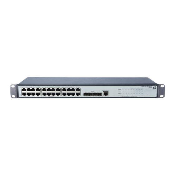
V1910-16G panel views Figure 1 Front panel (1) 10/100/1000Base-T auto-sensing Ethernet port (2) 1000Base-X SFP port (3) Console port (4) Port LED (5) Power LED (Power) Figure 2 Rear panel (1) AC-input power receptacle (2) Grounding screw V1910-24G panel views Figure 3 Front panel (1) 10/100/1000Base-T auto-sensing Ethernet port (2) 1000Base-X SFP port... -
Page 7: V1910-48G Panel Views
V1910-48G panel views Figure 5 Front panel (1) 10/100/1000Base-T auto-sensing Ethernet port (2) 10/100/1000Base-T Ethernet port LED (3) Console port (4) Power LED (Power) (5) 1000Base-X SFP port (6) 1000Base-X SFP port LED Figure 6 Rear panel (1) AC-input power receptacle (2) Grounding screw V1910-24G-PoE (170W) panel views Figure 7 Front panel... -
Page 8: V1910-24G-Poe (365W) Panel Views
Figure 10 Rear panel (1) DC receptacle (2) Screw hole of the plug (3) AC-input power receptacle (4) Grounding screw 1910-8G panel views Figure 11 Front panel (1) 10/100/1000Base-T auto-sensing Ethernet port (2) 1000Base-X SFP port (3) Console port (4) Port LED... -
Page 9: 1910-8G-Poe+ (65W) Panel Views
(5) Power LED (Power) Figure 12 Rear panel (1) AC-input power receptacle (2) Grounding screw 1910-8G-PoE+ (65W) panel views Figure 13 Front panel (1) 10/100/1000Base-T auto-sensing Ethernet port (2) Port LED mode switching button (3) Port LED (4) Power LED (Power) -
Page 10: 1910-8G-Poe+ (180W) Panel Views
1910-8G-PoE+ (180W) panel views Figure 15 Front panel (1) 10/100/1000Base-T auto-sensing Ethernet port (2) Port LED mode switching button (3) Port LED (4) Power LED (Power) (5) Port mode LED (6) Console port (7) 1000Base-X SFP port Figure 16 Rear panel... -
Page 11: Preparing For Installation
When replacing FRUs, wear an ESD-preventive wrist strap to avoid damaging the units. • Examining the installation site The HP 1910 switches must be used indoors. You can mount your switch in a rack or on a workbench, but make sure: •... -
Page 12: Cleanness
• overcurrent caused by lightning strikes. Laser safety The HP 1910 switches are Class 1 laser devices. WARNING! Do not stare into any fiber port when the switch has power. The laser light emitted from the optical fiber may hurt your eyes. -
Page 13: Installation Tools
Installation tools • Flathead screwdriver Phillips screwdriver • Needle-nose pliers • • Wire-stripping pliers Diagonal pliers • ESD-preventive wrist strap • Blow dryer • All these installation tools are user supplied. -
Page 14: Installing The Switch
HP for permission. Otherwise, HP shall not be liable for any consequence. Figure 17 Hardware installation flow Installing the switch in a 19-inch rack Figure 18 shows the general procedure for installing an HP 1910 switch in a 19-inch rack. -
Page 15: Mounting Brackets And Mounting Positions
Figure 18 Rack-mounting procedure Mounting brackets and mounting positions Table 5 Mounting brackets and positions for the HP 1910 switches Chassis Bracket view Mounting position • • V1910- 1 6G Front mounting (see Figure See callout A in Figure •... -
Page 16: Attaching The Mounting Brackets To The Switch Chassis
Repeat the preceding steps to attach the other mounting bracket to the chassis. Figure 20 Front mounting position for V1910-16G/V1910-24G Figure 21 Rear mounting position for V1910-16G/V1910-24G Figure 22 Front mounting position for 1910-8G Figure 23 Rear mounting position for 1910-8G... - Page 17 Figure 24 Front mounting position for 1910-8G-PoE+ (65W)/1910-8G-PoE+ (180W) Figure 25 Rear mounting position for 1910-8G-PoE+ (65W)/1910-8G-PoE+ (180W) Figure 26 Front mounting position for V1910-24G-PoE (170W)/V1910-24G-PoE (365W)/V1910-48G Figure 27 Mid-mounting position for V1910-24G-PoE (170W)/V1910-24G-PoE (365W) Figure 28 Rear mounting position for V1910-24G-PoE (170W)/V1910-24G-PoE (365W)/V1910-48G...
-
Page 18: Rack-Mounting The Switch
Rack-mounting the switch This task requires two persons. To mount the switch in a rack: Wear an ESD-preventive wrist strap and make sure it makes good skin contact and is well grounded. Check that the rack is well grounded and can support the weight of the switch chassis and all its accessories. - Page 19 Figure 30 Mounting the V1910-24G-PoE (170W)/V1910-24G-PoE (365W) chassis in a rack...
- Page 20 Figure 31 Mounting the 1910-8G chassis in a rack Figure 32 Mounting the 1910-8G-PoE+ (65W)/1910-8G-PoE+ (170W) chassis in a rack...
-
Page 21: Mounting The Switch On A Workbench
Place the switch with upside up on the workbench. Mounting the switch on a wall You can mount the HP 1910-8G, 1910-8G-PoE+ (65W), and 1910-8G-PoE+ (180W) switches on a concrete or wood wall by using two separately orderable wall-mounting anchor kits. - Page 22 34, drill two holes at the same height and make sure that the spacing in between is as follows: 1910-8G—98.5 mm (3.88 in) 1910-8G-PoE+ (65W)—174.0 mm (6.85 in) 1910-8G-PoE+ (180W)—174.0 mm (6.85 in) The hole depth and size depends on the anchors and screws you use. Make sure that you can push the anchors to their full depth in the holes, with their outer edges having a close contact with the wall, and tightly fasten the screws to the wall.
-
Page 23: Grounding The Switch
Figure 36 Wall mounting (1) Mounting hole in the switch chassis bottom Grounding the switch WARNING! Correctly connecting the switch grounding cable is crucial to lightning protection and EMI protection. The power input end of the switch has a noise filter, whose central ground is directly connected to the chassis to form the chassis ground (commonly known as PGND). - Page 24 Identify the grounding point (with a grounding sign) on the rear panel of the switch chassis, and remove the grounding screw from the grounding point. Attach the grounding screw to the OT terminal of the grounding cable. Use a screwdriver to fasten the grounding screw into the grounding screw hole. Figure 37 Connecting the grounding cable to the grounding hole of the switch chassis (1) Rear panel of the switch (2) Grounding sign...
-
Page 25: Grounding The Switch With A Grounding Conductor Buried In The Earth Ground
Figure 39 Connecting the grounding cable to a grounding strip (1) Grounding post (2) Grounding strip (3) Grounding cable (4) Hex nut Grounding the switch with a grounding conductor buried in the earth ground If the installation site has no grounding strips, but earth ground is available, hammer a 0.5 m (1.64 ft) or longer angle iron or steel tube into the earth ground to serve as a grounding conductor. -
Page 26: Grounding The Switch By Using The Ac Power Cord
Grounding the switch by using the AC power cord If the installation site has no grounding strips or earth ground, ground an AC-powered switch through the PE wire of the power cord. Make sure that: The power cord has a PE terminal. •... -
Page 27: Connecting The Ac Power Cord
Chassis Connection procedure reference 1910-8G V1910-16G V1910-24G V1910-48G Connecting the AC power cord 1910-8G-PoE+ (65W) 1910-8G-PoE+ (180W) V1910-24G-PoE (170W) AC-input: Connecting the AC power cord V1910-24G-PoE (365W) RPS input: Connecting the switch to a –52 to –55 VDC output RPS... -
Page 28: Verifying The Installation
Tighten the screws on the plug with a flat-blade screwdriver to secure the plug in the RPS receptacle (see callout 2 in Figure 43). Connect the other end of the power cord to the RPS. Make sure that the RPS is supplying power and verify that the RPS status LED is ON. Figure 43 Connect the RPS cable to the –52 to –55 RPS receptacle Verifying the installation After you complete the installation, verify that:... -
Page 29: Accessing The Switch For The First Time
Accessing the switch for the first time Setting up the configuration environment The first time you access the switch you must use a console cable to connect a console terminal, for example, a PC, to the console port on the switch. Figure 44 Connect the console port to a terminal Connecting the console cable Console cable... -
Page 30: Setting Terminal Parameters
NOTE: Identify the mark on the console port and make sure that you are connecting to the correct port. • The serial ports on PCs do not support hot swapping. If the switch has been powered on, connect the • console cable to the PC before connecting to the switch, and when you disconnect the cable, first disconnect from the switch. - Page 31 Figure 47 Set the serial port used by the HyperTerminal connection Set Bits per second to 38400, Data bits to 8, Parity to None, Stop bits to 1, and Flow control to None, and click OK. Figure 48 Set the serial port parameters Select File >...
- Page 32 Figure 49 HyperTerminal window On the Settings tab, set the emulation to VT100 and click OK. Figure 50 Set terminal emulation in Switch Properties dialog box...
-
Page 33: Powering On The Switch
The console cable is properly connected, the terminal or PC used for configuration has started, and • the configuration parameters have been correctly set. Powering on the switch Power on the switch, for example, an HP V1910-24G switch, and you can see the following information: Starting..************************************************************************ HP V1910-24G Switch JE006A BOOTROM, Version 135 ************************************************************************ Copyright (c) 2010-2011 Hewlett-Packard Development Company, L.P. - Page 34 Restart the switch. NOTE: The system by default has no Boot ROM password. HP recommends that you set a Boot ROM password immediately after you access the Boot menu. If you perform no operation or press any key other than Ctrl + B within one second, the system •...
-
Page 35: Changing The Startup Mode
User interface aux0 is available. Press ENTER to get started. Press Enter at the prompt, and you can configure the switch when the prompt <HP> appears. Changing the startup mode The system by default starts up in fast mode. To change to the full startup mode, press Ctrl + B within one... - Page 36 User interface aux0 is available. Press ENTER to get started. Press Enter at the prompt, and you can configure the switch when the prompt <HP> appears. NOTE: For more information about the configuration commands and CLI, see the configuration guides and...
-
Page 37: Maintenance And Troubleshooting
The V1910-24G-PoE (365W) adopts AC power input, RPS power input, or both RPS and AC power inputs. Other 1910 switches adopt AC power input only. You can look at the power LED and the RPS status LED on the front panel of the switch to identify a power system failure. -
Page 38: Configuration Terminal Problems
The external RPS is correctly working. • NOTE: If the problem persists, contact the HP technical support for help. Configuration terminal problems If the configuration environment setup is correct, the configuration terminal displays booting information when the switch is powered on. If the setup is incorrect, the configuration terminal would display nothing or garbled text. - Page 39 Baud rate—38,400 • • Data bits—8 Parity—none • Stop bits—1 • • Flow control—none Emulation—VT100 •...
-
Page 40: Support And Other Resources
Related information Documents To find related documents, browse to the Manuals page of the HP Business Support Center website: http://www.hp.com/support/manuals For related documentation, navigate to the Networking section, and select a networking category. •... -
Page 41: Conventions
Conventions This section describes the conventions used in this documentation set. Command conventions Convention Description Boldface Bold text represents commands and keywords that you enter literally as shown. Italic Italic text represents arguments that you replace with actual values. Square brackets enclose syntax choices (keywords or arguments) that are optional. Braces enclose a set of required syntax choices separated by vertical bars, from which { x | y | ... - Page 42 Network topology icons Represents a generic network device, such as a router, switch, or firewall. Represents a routing-capable device, such as a router or Layer 3 switch. Represents a generic switch, such as a Layer 2 or Layer 3 switch, or a router that supports Layer 2 forwarding and other Layer 2 features.
-
Page 43: Appendix A Technical Specifications
V1910-16G 43.6 × 440 × 160 mm ≤ 3 kg (6.61 lb) (1.72 × 17.32 × 6.30 in) V1910-24G 1910-8G-PoE+ (65W) 43.6 × 300 × 260 mm ≤ 3 kg (6.61 lb) (1.72 × 11.81 × 10.24 in) 1910-8G-PoE+ (180W) V1910-24G-PoE (170W) 43.6 ×... -
Page 44: Power Specifications
Power input types Chassis AC-input power receptacle RPS receptacle All 1910 chassis but the V1910-24G-PoE (365W) V1910-24G-PoE (365W) The RPS can supply power to your switch when the AC power line fails or cannot supply sufficient power. AC input voltage specifications... -
Page 45: Cooling System
740 W at 27.5 W at input input RPS DC input RPS DC input V1910-24G-PoE 30 W 170 W 25.0 W 255 W (170W) Cooling system Chassis Fixed fans 1910-8G 1910-8G-PoE+ (65W) V1910-16G V1910-24G V1910-48G 1910-8G-PoE+ (180W) V1910-24G-PoE (170W) V1910-24G-PoE (365W) -
Page 46: Appendix B Frus And Compatibility Matrixes
Appendix B FRUs and compatibility matrixes This appendix describes the FRUs available for the HP 1910 switches and their compatibility. SFP transceiver modules and SFP Stacking Kit NOTE: To guarantee the functionality of the SFP ports, use only HP SFP transceiver modules. - Page 47 Module description diameter transmission code bandwidth (μm) distance (nm) (MHz × km) HP X120 1G SFP RJ45 T Category-5 100 m JD089B Transceiver twisted pair (328.08 ft) HP A3600 Switch SFP JD324A UTP/STP 1.5 m (4.92 ft)
-
Page 48: Appendix C Ports And Leds
Category-5 (or above) twisted pair cable Standards IEEE 802.3i, 802.3u, 802.3ab SFP port All HP 1910 switches have 1000Base-X SFP ports. For the SFP transceiver modules available for the HP 1910 switches, see “SFP transceiver modules and SFP Stacking Kit.”... -
Page 49: Leds
The RPS unit is not connected or the RPS DC input is abnormal. Port mode LED The 1910-8G-PoE+ (65W), 1910-8G-PoE+ (180W), V1910-24G-PoE (170W), and V1910-24G-PoE (365W) switches have a port mode LED to indicate the type of information that the network port LEDs (excluding the SFP port LEDs) are showing. -
Page 50: 10/100/1000Base-T Ethernet Port Led
The V1910-48G switch has one bi-color LED (see Table 14) for each 10/100/1000Base-T Ethernet port, and all other HP 1910 switches have two LEDs (see Table 15) for each 10/100/1000Base-T Ethernet port. The 1910-8G-PoE+ (65W), 1910-8G-PoE+ (180W), V1910-24G-PoE (170W), and V1910-24G-PoE... -
Page 51: 1000Base-X Sfp Port Led
Port mode LED (Mode) Port LED Port LED status Description status The port has no link or is not operating at 1000 Mbps. The port is operating at 10/100 Mbps. The port is sending or receiving data at Yellow Fast flashing 10/100 Mbps. -
Page 52: Index
C E G I L M P R S V Configuration terminal problems,34 Password loss,33 Connecting the console cable,25 Physical specifications,39 Connecting the power cord,22 Ports,44 Contacting HP,36 Power specifications,40 Conventions,37 Power supply failure,33 Cooling system,41 Powering on the switch,29 Environmental specifications,39 Related...
Need help?
Do you have a question about the 1910 and is the answer not in the manual?
Questions and answers