
Related Manuals for HP V1910 Series


Summary of Contents for HP V1910 Series
-
Page 1: Getting Started Guide
HP V1910 Switch Series Getting Started Guide 59982236 Part number: 5998-2236 Document version: 6W100-20110615... - Page 2 The only warranties for HP products and services are set forth in the express warranty statements accompanying such products and services. Nothing herein should be construed as constituting an additional warranty.
- Page 3 Preface The HP V1910 Switch Series Getting Started Guide describes the appearance, installation, power-on, maintenance, and troubleshooting of the HP V1910 switches. This preface includes: Audience Conventions Contacting HP Subscription service Warranty Documents Audience...
-
Page 4: Subscription Service
Warranty The Hewlett-Packard Limited Warranty Statement for this product and the HP Software License Terms which apply to any software accompanying this product are available on the HP networking Web site www.hp.com/networking/warranty. The customer warranty support and services information are available on the HP networking Web site at www.hp.com/networking/support. - Page 5 http://www.hp.com/support/manuals...
-
Page 6: Table Of Contents
Contents Product overview ·························································································································································· 1 About the HP V1910 Switch Series ································································································································ 1 HP V1910-16G Switch JE005A ······································································································································ 2 Front panel ································································································································································ 2 Rear panel ································································································································································· 3 Power supply system ················································································································································ 3 Cooling system ························································································································································· 3 HP V1910-24G Switch JE006A ······································································································································ 3 Front panel ································································································································································... - Page 7 Introduction to mounting brackets ························································································································ 16 Attaching the mounting brackets to the switch ··································································································· 16 Mounting the switch to a rack ······························································································································ 18 Mounting the switch on a workbench ·························································································································· 20 Grounding the switch ···················································································································································· 20 Grounding the switch with a grounding strip ····································································································· 21 Grounding the switch with a grounding conductor buried in the earth ground ·············································...
-
Page 8: Product Overview
Product overview About the HP V1910 Switch Series HP V1910 Switch Series is a line of Layer 2 Gigabit Ethernet switching products developed by Hewlett-Packard Development Company, L.P. (hereinafter referred to as HP). The V1910 switches are intelligent manageable switches designed for network environments where high performance, high-density port distribution, and easy installation are required. -
Page 9: Hp V1910-16G Switch Je005A
Rated voltage range: 100 VAC to 240 VAC, 50 Hz or 60 Hz Maximum voltage range: 90 VAC to 264 VAC, 47 Hz or 63 Hz Input Use the external RPS unit provided by HP voltage RPS DC only, with the rated voltage ranging from –52 VDC to –55 VDC... -
Page 10: Rear Panel
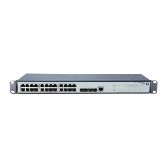
Rated voltage range: 100 VAC to 240 VAC, 50 Hz or 60 Hz Input voltage range: 90 VAC to 264 VAC, 47 Hz or 63 Hz Cooling system The HP V1910- 1 6G Switch JE005A is equipped with one fan for heat dissipation HP V1910-24G Switch JE006A Front panel... -
Page 11: Power Supply System
Rated voltage range: 100 VAC to 240 VAC, 50 Hz or 60 Hz Input voltage range: 90 VAC to 264 VAC, 47 Hz or 63 Hz Cooling system The HP V1910-24G Switch JE006A is equipped with one fan for heat dissipation. HP V1910-48G Switch JE009A Front panel... -
Page 12: Cooling System
Rated voltage range: 100 VAC to 240 VAC, 50 Hz or 60 Hz Input voltage range: 90 VAC to 264 VAC, 47 Hz or 63 Hz Cooling system The HP V1910-24G-PoE (170W) Switch JE008A is equipped with three fans for heat dissipation. -
Page 13: Hp V1910-24G-Poe (365W) Switch Je007A
(2) Screw hole of the plug (3) AC receptacle (4) Grounding screw Power supply system The HP V1910-24G-PoE (365W) Switch JE007A can adopt AC power input, or DC power input, or both to provide backup AC power input: Rated voltage range: 100 VAC to 240 VAC, 50 Hz or 60 Hz... -
Page 14: Cooling System
Cooling system The HP V1910-24G-PoE (365W) Switch JE007A is equipped with six fans for heat dissipation. Ports Console port Each V1910 switch provides one console port on the front panel. Table 3 Console port specifications Item Specification Connector type RJ-45... - Page 15 Transceiver her. NOTE: To guarantee the functionality of the SFP ports, always use HP SFP transceiver modules on the HP V1910 Switch Series. The SFP transceiver modules available for this switch series are subject to change over time. For the most ...
-
Page 16: Leds
The switch has been powered off. RPS status LED The HP V1910-24G-PoE (365W) Switch JE007A provides an RPS status LED on its front panel, indicating the working status of the RPS of the switch. Table 8 Description of the RPS status LED... -
Page 17: Port Mode Led
10/100/1000Base-T auto-sensing Ethernet port status LED NOTE: Each port of the HP V1910-48G Switch JE009A has a bi-color LED indicating its status. Each port of other models of the V1910 Switch Series has two LEDs, with only one in the ON state at a time. -
Page 18: 1000Base-X Sfp Interface Status Led
1000Base-X SFP interface status LED NOTE: For the HP V1910-24G-PoE (170W) Switch JE008A and HP V1910-24G-PoE (365W) Switch JE007A, the port mode switching button does not take effect for the 1000Base-X SFP interface LEDs. Table 11 1000Base-X SFP interface status LEDs description... -
Page 19: Preparing For Installation
Preparing for installation Safety recommendations To avoid any device impairment and bodily injury caused by improper use, observe these rules: Before cleaning the switch, unplug the power cord of the switch first. Do not clean the switch with wet cloth or liquid. Do not place the switch near water or in a damp environment. -
Page 20: Cleanness
Cleanness Dust buildup on the chassis may result in electrostatic adsorption, which causes poor contact of metal components and contact points, especially when indoor relative humidity is low. In the worst case, electrostatic adsorption can cause communication failure. Table 12 Dust concentration limit in the equipment room Substance Concentration limit (particles/m Dust... -
Page 21: Installation Tools
Installation tools Flat-blade screwdriver Phillips screwdriver ESD-preventive wrist strap All these installation tools are user supplied. -
Page 22: Installing The Switch
Keep the tamper-proof seal on a mounting screw on the chassis cover intact, and if you want to open the chassis, contact the local agent of HP for permission. Otherwise, HP shall not be liable for any consequence caused thereby. -
Page 23: Installing The Switch Into A 19-Inch Rack
Introduction to mounting brackets Table 14 Mounting brackets for the V1910 Switch Series Mounting Model Appearance Mounting position Description brackets HP V1910-16G Switch JE005A Provided See callout A Front or rear part of the Figure 14 by default Figure 13 chassis’s side... - Page 24 As shown in Table 14, the mounting brackets can be attached to the switch for front, center, or rear mounting. You can choose a proper position according to the actual requirements. Follow these steps to install a mounting bracket to the chassis: Align the mounting holes of the bracket with the holes of the chassis, as shown in Figure 14~Figure Step1...
-
Page 25: Mounting The Switch To A Rack
Figure 18 Install a mounting bracket on the chassis (E) Mounting the switch to a rack Wear an ESD-preventive wrist strap and make sure the rack is well grounded and is firm enough to Step1 support the switch and cables. Locate the positions for installing cage nuts on the rack post, and use a marker to mark the positions. - Page 26 Figure 19 Mount the HP V1910-16G Switch JE005A to a rack Figure 20 Mount the HP V1910-24G-PoE (170W) Switch JE008A to a rack...
-
Page 27: Mounting The Switch On A Workbench
NOTE: If support trays are provided on the rack, you can mount the switch to the rack with mounting brackets and trays. To do so, put the switch on the support tray and slide the switch to an appropriate location, and then fix the mounting brackets. -
Page 28: Grounding The Switch With A Grounding Strip
CAUTION: Correctly connecting the switch grounding cable is crucial to the lightning protection and EMI protection. The power interface and grounding terminals in this section are for illustration only. The power input end of the switch has a noise filter, whose central ground is directly connected to the chassis to form the chassis ground. -
Page 29: Grounding The Switch With A Grounding Conductor Buried In The Earth Ground
(3) Grounding cable (4) Hex nut CAUTION: Only the grounding cables supplied with the HP V1910-24G-PoE (365W) Switch JE007A and HP V1910-24G-PoE (170W) Switch JE008A provide OT terminals at the ends connecting the grounding strip. For other switch models, prepare proper OT terminals by yourself. -
Page 30: Grounding The Switch In Other Grounding Environments
Grounding the switch in other grounding environments Grounding an AC-powered switch If the installation site has no grounding strips or earth ground, you ground an AC-powered switch through the PE wire of the AC power supply. Make sure the PE wire is well connected to the ground at the power distribution room or AC transformer side, the switch PE terminal and the PE wire are well connected, and the three-wire input cable of the grounding cable is used for the power supply cable. -
Page 31: Connecting An Rps Dc Power Cord
Figure 25 Connect the AC power cord (A) Connecting an RPS DC power cord The HP V1910-24G-PoE (365W) Switch JE007A also supports RPS DC power input with the input voltage ranging from –52 V to –55 V. Follow these steps to install a DC power cord:... -
Page 32: Verifying The Installation
Verifying the installation Before powering on the switch, check that: There is enough space for heat dissipation around the switch, and the rack or workbench is stable. The grounding cable is securely connected. The selected power module matches that required by the switch. ... -
Page 33: Powering On The Switch For The First Time
Powering on the switch for the first time Setting up the configuration environment To set up the configuration environment, connect a terminal (a PC in this example) to the console port on the switch with a console cable. Figure 27 Network diagram for configuration environment setup Connecting the console cable Console cable A console cable is an 8-core shielded cable, with a crimped RJ-45 connector at one end for connecting... -
Page 34: Connection Procedure
RJ-45 Signal Direction DB-9 → → → → Connection procedure Follow these steps to connect a terminal device to the switch by using the console cable: Plug the DB-9 female connector of the console cable to the serial port of the console terminal or PC. Connect the RJ-45 connector of the console cable to the console port of the switch. - Page 35 Figure 29 Connection description of the HyperTerminal Type the name of the new connection in the Name text box and click OK. The following dialog box Step2 appears. Select the serial port to be used from the Connect using drop-down list. Figure 30 Set the serial port used by the HyperTerminal connection Click OK after selecting a serial port.
- Page 36 Figure 31 Set the serial port parameters Click OK after setting the serial port parameters and the system enters the HyperTerminal window shown Step4 below. Figure 32 HyperTerminal window...
-
Page 37: Powering On The Switch
Powering on the switch The V1910 switches have the same Boot ROM display style. This document uses the Boot ROM output information on the HP V1910-24G Switch JE006A as an example: Starting..************************************************************************... - Page 38 ************************************************************************ Copyright (c) 2010-2011 Hewlett-Packard Development Company, L.P. Creation Date : Jan 9 2011 CPU Type : ARM926 CPU L1 Cache : 32KB CPU Clock Speed : 333MHz Memory Type : DDR2 SDRAM Memory Size : 128MB Flash Size : 128MB CPLD Version : 001 PCB Version...
-
Page 39: Changing The Boot Mode
The appearance of "Press ENTER to get started" indicates that the automatic startup of the switch is complete. Press Enter. The following prompt is displayed: <HP> You can configure the switch now. Changing the boot mode By default, the system starts up in fast boot mode. If you want to change the boot mode to normal, press... - Page 40 Enter your choice(0-9): Enter 0. The system reboots in normal startup mode and displays the following information: Starting..************************************************************************ HP V1910-24G Switch JE006A BOOTROM, Version 135 ************************************************************************ Copyright (c) 2010-2011 Hewlett-Packard Development Company, L.P. Creation Date : Jan 9 2011...
- Page 41 User interface aux0 is available. Press ENTER to get started. The appearance of "Press ENTER to get started" indicates that the automatic startup of the switch is complete. Press Enter. The following prompt is displayed: <HP> You can configure the switch now.
-
Page 42: Maintenance And Troubleshooting
Maintenance and troubleshooting Software loading failure The switch runs with the original software version after it has failed to load new version of software. To identify and remove the loading failure cause, perform the following check procedure: Check that the physical ports are properly connected. ... -
Page 43: Power Supply Failure
Power supply failure The HP V1910-24G-PoE (365W) Switch JE007A adopts AC power input, RPS power input, or both RPS and AC power inputs. Other V1910 switches adopt AC power input only. You can look at the power LED and the RPS status LED on the front panel of the switch to identify a power system failure. -
Page 44: Configuration Terminal Problems
Configuration terminal problems If the configuration environment setup is correct, the configuration terminal displays booting information when the switch is powered on. If the setup is incorrect, the configuration terminal would display nothing or garbled text. No terminal display If the configuration terminal displays nothing when the switch is powered on, check that: ...
Need help?
Do you have a question about the V1910 Series and is the answer not in the manual?
Questions and answers